Curve array probe (left), linear array probe 38 mm (middle), and linear array probe 25 mm (right).
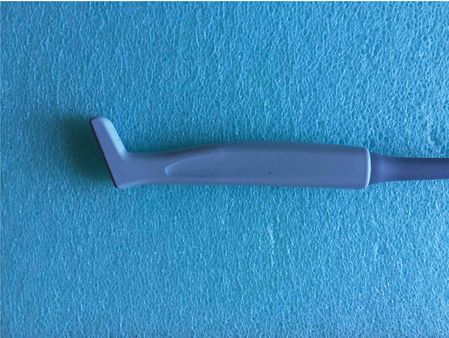
“Hockey-stick” type probe.
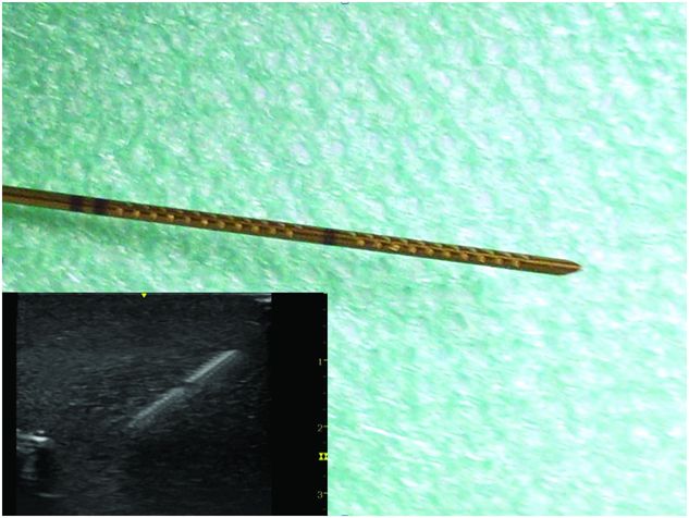
Specific needle covered with “cornerstone” reflectors providing optimal sonographic visibility of the tip.
Technique of puncture
The first step in ultrasound-guided nerve blocks is to visualize all the anatomic structures in the target area. Two techniques of puncture can be performed depending on the needle position relative to the probe:
1. The out-of-plane technique: The needle is inserted perpendicular to the long axis of the probe. The needle then appears as a hyperechoic dot if the angulation of the needle does not exceed 45 degrees to the wave front (Figure 5.3). Introducing the needle too close to the probe will make it more difficult to see the tip. The needle position can also be identified by tissue movement and displacement, by a dorsal acoustic shadow emerging distal to the tip, or by injection of a small volume of saline or LA. Small translation movements of the probe can also determine the location of the needle tip. The difficulty in this approach is that one is trying to locate the needle tip only, and not the whole needle.
2. The in-plane technique: The needle is aligned to the long axis of the probe, allowing the visualization of the needle shaft and tip (Figure 5.4). This technique, while allowing more of the needle to be seen, can still be difficult because it requires that the needle be directly in the ultrasound beam. The probe orientation is very important because small deviations of the probe from the needle path will remove the needle from the screen image. As the probe is typically positioned perpendicular to the nerve, therefore the needle is advanced perpendicular to the long axis of the nerve. This approach may be safer because it allows one to track the progress of the needle (and the tip) in real-time.
It is important to note that, regardless of the approach taken, the trajectory of the needle can be completely different from those customarily used in the nerve stimulation, blind, or “pop” techniques.
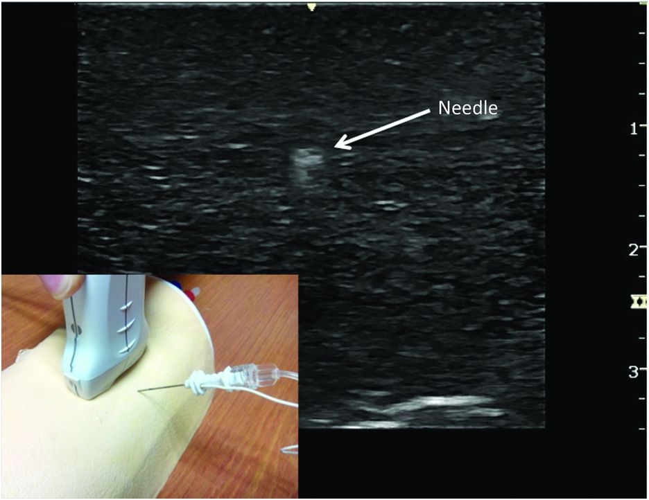
Visualization of the tip of the needle with out-of-plane technique (performed in phantom).
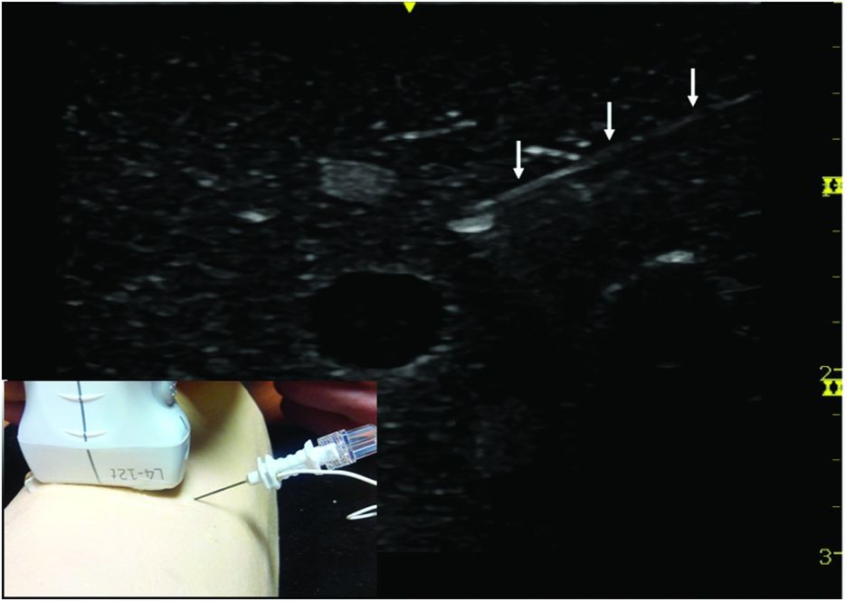
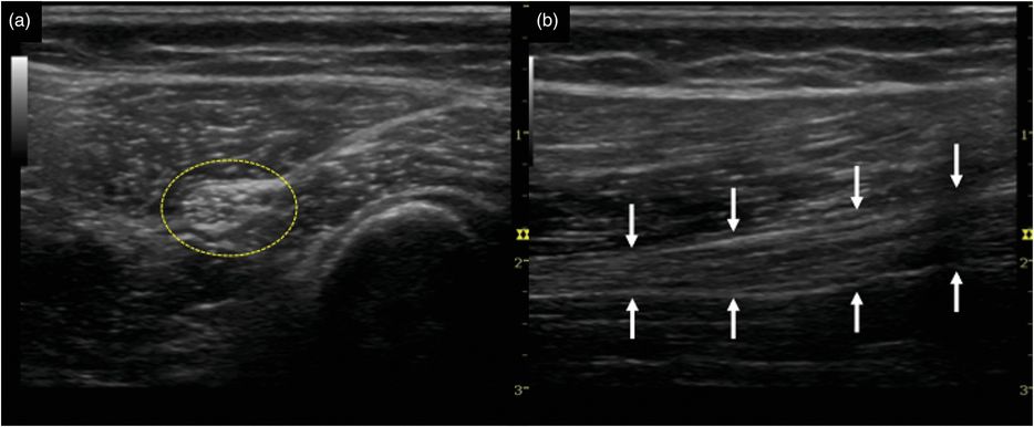
Visualization of the needle with in-plane technique (performed in phantom).
Identification of structures in ultrasonography
Neural structures
Nowadays, with the improved resolution of modern ultrasound machines and their associated software, the majority of peripheral nerves for regional anesthesia can be visualized in children. These images are not static and can alter depending on the position of the child, the pressure of the probe on the skin, the progression of the needle, or the injection of LA. Neuronal structures can be imaged transversally (axially) or longitudinally (Figure 5.5). Most imaging is done with the probe scanning the cross-section of the nerve (perpendicular to the long axis of the nerve), allowing the identification of the target nerve, evaluation of its depth, and finding the optimal angle of the probe for maximum echogenicity from the nerve. This change of echogenicity depending on which angle of inclination the transducer is at, is termed anisotropy.
Adjusting for a number of variables on the ultrasound machine can optimize the view of neural structures. These include depth, gain, and frequency and will vary depending on the nerve to be located. Each ultrasound machine is different in terms of how to adjust these settings. The common term is “knobology,” and we recommend that the relevant ultrasound machine company provide training before use.
Peripheral nerves may have a hypoechoic (dark structure) or hyperechoic (bright structure) sonographic appearance, depending on the size of the nerve, the sonographic frequency, and the angle of the ultrasound beam. The proximal part of a plexus usually appears hypoechoic, while distal portions are hyperechoic. It is possible to identify the internal structure of a nerve with high frequency transducers. The hypoechoic structures are the fascicles of the nerves while the hyperechoic background reflects the connective tissue between neuronal structures. It is important to note that each nerve has a particular appearance in ultrasonography with regard to its shape and echogenicity. The nerve may also take various shapes (round, oval, or triangular) according to its anatomic location and the surrounding tissues.
Visualization of neural structures is age dependant, particularly of the spinal region. In children, nerve and vascular structures are naturally smaller, at more superficial depths, and usually there is less adipose tissue or muscle septae. In infants less than 1 year of age, the spine and associated structures are readily imaged, but this clarity rapidly decreases as ossification of the vertebral column increases with age. Contrary to the “loss of resistance” technique, the main structure to identify is not the ligament flavum but the dura mater to measure depth. Neuraxial structures can be visualized using a longitudinal or transverse approach.
Adjacent structures
In ultrasound guidance, the ability to identify adjacent structures is crucial to avoid any confusion with the neural structures:
Bones: The cortex of bone is hyperechoic and appears as a white line on the ultrasound image. The ultrasound beam being totally reflected, a distal shadow (completely anechoic) is located behind this white line of bone cortex (Figure 5.6).
Vessels: The vessels are identified as round or oval anechoic shape. Their appearance may vary depending on the pressure exerted by the probe, particularly for veins which are easily compressible. Discrimination between arteries and veins is possible with color Doppler (Figure 5.7). It is important to identify the vessels during ultrasound-guided regional anesthesia in order to avoid intravascular injection.
Tendons: During ultrasound-guided regional anesthesia, tendons can cause the most confusion because they have a very similar sonographic appearance to nerves. To distinguish between both, it is important to track them over a short distance. Tendons disappear while the nerves remain visible over these distances.
Muscles: Muscles have a fibrolamellar sonographic appearance. Muscles may appear as either heterogeneous structures with hyperechoic intramuscular septae or homogenous structures (Figure 5.6). Some muscles or their septae are important as they allow easier identification of the target nerve or the space for injection of LA (transversus abdominis plane block or ilioinguinal/iliohypogastric block).
Related posts:
 Ultrasound-guided supraclavicular brachial plexus block
 Ultrasound-guided ilioinguinal/iliohypogastric block
 Ultrasound-guided transversus abdominis plane block
 Ultrasound-guided rectus sheath block
 Ultrasound for spinal anesthesia
 Anatomy of the neuraxis, thoracic and abdominal walls, upper and lower limbs
Stay updated, free articles. Join our Telegram channel

Full access? Get Clinical Tree


