Tom C. Krejcie
It is common for students, nurses, and physicians in the embryonic phase of their anesthesiology training to be intimidated when confronted by the current iteration of the anesthesia machine, the anesthesia workstation. The sheer number of cables, hoses, knobs, digital displays, and alarms may seem formidable. This chapter aims to deconstruct the anatomy and functionality of the conventional anesthesia workstation and characterize the principles underlying its use.
As a salient and indispensable component of the operating room environment, the anesthesia workstation serves to achieve four goals: 1) provide a reliable mechanism to continually ventilate the anesthetized patient, 2) serve as a source for supplemental O2, 3) provide a mechanism for the delivery of volatile anesthetic agents, and 4) serve as a monitor and early-warning system for several potential hazards encountered in clinical anesthetic care. Note that a variety of simple tools exist to achieve each of these goals individually (e.g., a bag-valve-mask device [Ambu-bag] may be used to ventilate a patient’s lungs and a simple E-cylinder filled with pressurized oxygen may be used to increase the fraction of inspired oxygen [FiO2]). The anesthesia workstation, however, incorporates and consolidates all of the above goals in a manner that is convenient and allows the anesthesiologist to be more vigilant in performing other equally important facets of anesthetic care. It cannot be overemphasized that this convenience comes at the price of complexity. Many intraoperative crises can be avoided by appreciating the design, functionality, and limitations of modern anesthesia workstations.

The modern anesthesia workstation is a sophisticated device that contributes to patient safety, but like many modern devices, it is complex and may fail. A simple self-inflating bag and mask must always be immediately available.
I. Functional Anatomy of the Anesthesia Workstation
In its entirety, the anesthesia workstation encompasses a broad range of equipment, including the anesthesia machine, physiologic monitors, and accessories such as active suction equipment and adjunctive bag-valve-mask device. Patient monitoring and airway management are discussed elsewhere. The remainder of this chapter directs attention specifically to the anesthesia machine. The basic construct of the anesthesia machine is defined by three concepts (Fig. 14-1). The first is a system that originates with a gas; typically this is pressurized oxygen/air delivered from a central hospital source, directly into the operating room. A series of pressure-reducing systems follows, after which the anesthesiologist directly controls the flow of these gases to achieve the desired flow rate and oxygen concentration that is delivered to the second system. Integrated into this gas delivery design is the anesthetic vaporizer, which allows for the administration of volatile anesthetic to the patient.
 VIDEO 14-1
Testing a Bag Valve Device
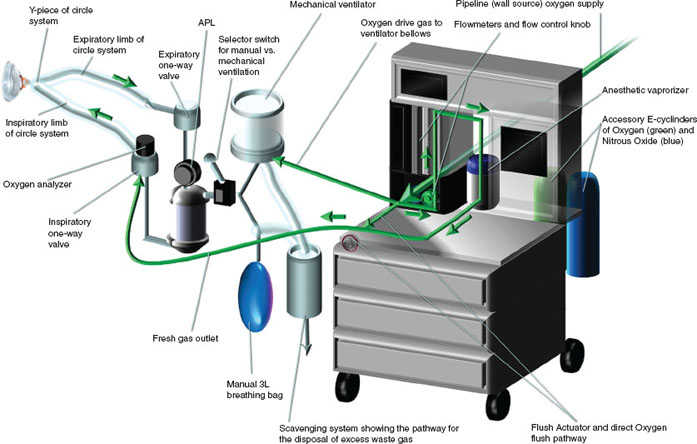
FIGURE 14-1 Representation of a typical anesthesia workstation. Arrows indicate direction of oxygen flow. Pipeline sources of air and nitrous oxide are not shown. APL, adjustable pressure-limiting valve.
The system described above converges on the fresh gas outlet, which delivers the desired concentrations of gases and volatile anesthetics into the next conceptual framework (system) of the anesthesia machine: the anesthesia breathing apparatus. Patient ventilation is achieved through the use of either the automated controlled mechanical ventilator or manually through the breathing bag, both of which are incorporated into a system of corrugated tubes and unidirectional valves known as the circle system. This design enables reciprocal inflation and deflation of the patient’s lungs with the ventilator or breathing bag. It also incorporates an absorbent compound to neutralize expired carbon dioxide.
Lastly, there must be a mechanism to remove excess gas or pressure from the system. This is accomplished through another structural arrangement, the scavenging system. The mechanics, safeguards, and hazards of each of these three systems will be discussed below.
II. Delivery of Gases: High, Intermediate, and Low Pressure Systems
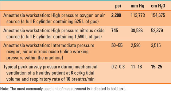
Most anesthesia workstations receive a dual supply of medical-grade gases. Oxygen is delivered at high pressure from the central hospital supply source (liquid oxygen tanks) into the operating room through readily visible green hoses, or alternatively, can be delivered from a cylinder (size E) of oxygen attached to the anesthesia machine. Air is color coded in yellow. Note that these color designations apply to medical centers located in the United States and vary internationally. A third supply line of nitrous oxide at high pressure, coded in blue, may also be present, or a backup supply of nitrous oxide stored in an E cylinder attached to the anesthesia machine (1). The delivery of these gases through the anesthesia machine and ultimately to the patient is marked by a progressive, regulated decrement in pressure. Wall source gases are delivered to the anesthesia machine at a pressure of 50 pounds per square inch (psi). E cylinders contain considerably higher pressures but are regulated to 45 psi prior to their interface with the anesthesia machine (1,2). The user further regulates and fine tunes the low-pressure flow of gases to the patient using flow control knobs specific to each gas. Table 14-1 lists pressure readings encountered in the anesthesia workstation.
Table 14-1 Pressure Readings Encountered in an Anesthesia Workstation

Most operating rooms have reliable piped in oxygen. However, if this should fail, a low pressure alarm will be triggered. The hose should be disconnected and the auxiliary E cylinder of oxygen turned on.
Pressure gauges reflective of both wall and cylinder sources of medical gases are displayed on the anesthesia machine. The gauges for the central hospital gas source measures the intermediate in-line working pressure and typically reads approximately 50 to 55 psi. The most common reason why this pressure reading would decrease is that the hose from the wall source has been disconnected from the anesthesia machine, but it could also result from a complete or partial failure of the central hospital gas source. This pressure gauge reading remains constant through the routine and continuous use of wall source gases even when used at high flow rates. In contrast, the gauges for medical cylinders reflect the high internal pressure of the cylinders themselves. A full E cylinder of oxygen or air will contain roughly 625 L of gas at a pressure of 2,200 psi. The pressure will drop proportionately as these gases are used (1–3). If a tank is used to oxygenate the patient at 10 L/min, then it will only last approximately 60 minutes (4). A full tank of nitrous oxide contains 1,590 L of gas at a pressure of 745 psi. Nitrous oxide, in contrast to oxygen and air, exists as a combination of liquid and gas at room temperature due to its physicochemical properties and critical temperature. As a result, continuous use of a nitrous oxide cylinder will not result in a pressure drop at the gauge until nearly 75% (1,200 L) of the nitrous oxide in the cylinder has been used. During the routine use of the anesthesia machine, the E cylinder sources are kept in the off position as these are intended for use only during central pipeline failure. If such an event occurs, two actions are to be undertaken. First, the central pipeline gas source is disconnected from the anesthesia machine. Second, the E cylinder is turned to the on position so that continued oxygenation and ventilation of the patient may proceed (1–3).
A. Flowmeters
From the flowmeter assembly onward, the anesthesia machine is considered a low pressure system. The anesthesiologist may individually manipulate the flow of air, oxygen, and nitrous oxide to achieve flow rates of 0.2 L/min to more than 10 L/min for each gas. The fine control over the flow of these gases is achieved as they pass through specialized, variable orifice glass tubes known as Thorpe tubes. The height of a floating bobbin within the tapered lumen (increasing internal diameter) of these tubes indicates the current flow rate being used (Fig. 14-2). At very low flow rates (0.1 to 0.3 L/min), the passage of gas molecules through the smaller diameter section of these tubes is laminar. Concentric telescoping tubes of gas molecules moving parallel to one another in this fashion are influenced by gas viscosity, or, in other words, the frictional properties between the inner surface of an outer layer of gas flow against the outer surface of the inner layer adjacent to it. In contrast, at high flow rates in the large diameter section of the Thorpe tube (5 to 10 L/min), gas flow is turbulent, which is characterized by the random trajectory of gas molecules, though en masse there is bulk movement of air in the antegrade direction. In this scenario, flow is significantly affected by gas density. Larger gas molecules will result in greater intermolecular collisions and hence greater impedance to gas flow (1,2).
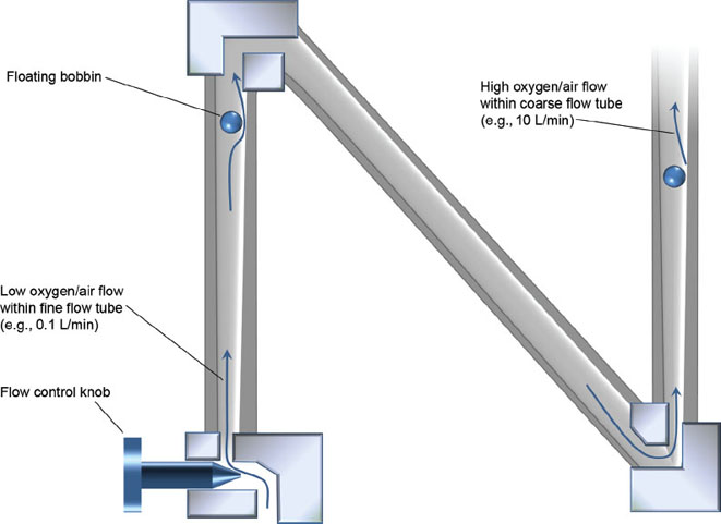
FIGURE 14-2 A flowmeter assembly and Thorpe tube. The black circle represents the floating bobbin, which indicates the current flow rate being used. Low flows at the narrow end of the tapered glass tube (e.g., 100 cc/min) are characterized as laminar and viscosity dependent. In contrast, high flows at the large diameter end of the tube (e.g., 10 L/min) are turbulent and density dependent.
B. Flush Actuator and One-Way Check Valve
Thus far, the discussion of gas delivery from its source to the patient has followed a single path that begins with very high pressures. However, it is ultimately received by the patient’s lungs under low pressure conditions within agreeably physiologic limits. Anesthesia machines are equipped with an alternate pathway for oxygen that may expose the patient to the intermediate pressure system. The flush actuator permits the application of oxygen flow from the in-line working pressure of 55 psi through the common gas outlet to the patient. Flow rates of oxygen through this alternate pathway that bypasses the flowmeters can range from 35 to 75 L/min. As a matter of perspective, using the flush valve to inflate a patient’s lungs exposes the patient to roughly 200 times the typical inflation pressures used during routine mechanical ventilation. One may wonder why this pathway exists at all? Should the patient somehow become disconnected from the anesthesia breathing apparatus during controlled ventilation, the ventilator bellows (or the breathing bag) will immediately deflate as the volume of gas within will be drained into the operating room environment. The flush actuator could be used to rapidly increase the volume of gas in the system, so that normal tidal volumes may resume. This should be undertaken with care and advisably only during the expiratory phase of respiration when any excess gas or pressure resulting from the use of the flush valve can be scavenged away from the system (see “Scavenging Systems” later in this chapter). Additionally, the flush valve may be used for more complex ventilation strategies such as high-frequency jet ventilation (1,2).

The oxygen flush actuator (“flush valve”) delivers oxygen at high pressure and flow directly to the common gas outlet. Its primary purpose is to enable rapid filling of a deflated rebreathing bag or ventilator bellows.
A further consideration involves the potential presence of a one-way check valve just upstream of where the flush actuator joins the fresh gas outlet to the patient. This valve is present on many models of Datex Ohmeda (GE Healthcare Company) brand workstations and allows for the unidirectional flow of gas only in the antegrade route. As a consequence, using the flush valve exposes the patient to all of the oxygen flow from the intermediate pressure system. In the absence of this one-way check valve, as is the case in Dräger workstations (Dräger Medical Inc.), some of the oxygen flow from flushing the system may course in a retrograde fashion (Fig. 14-3) (1).
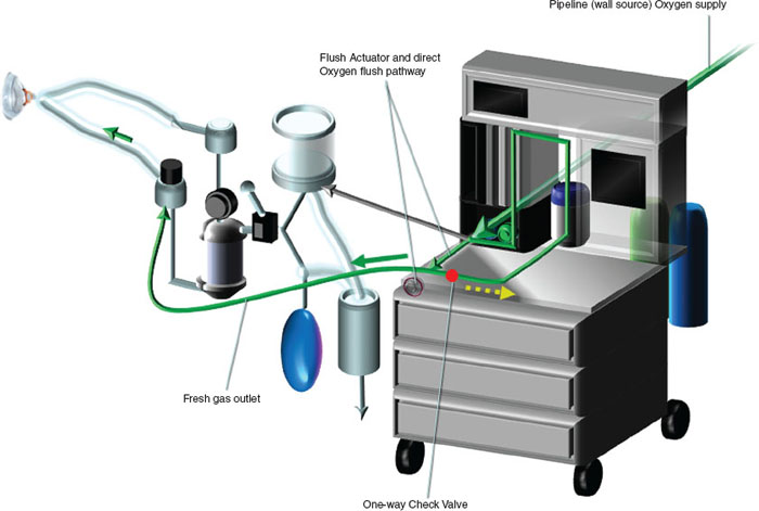
FIGURE 14-3 Oxygen flush actuator showing how the high pressure (50 pounds per square inch) of oxygen can bypass the flowmeters and be directly administered to the patient. The presence of a one-way check valve (red dot) forces all of the high-flow oxygen to course antegrade into the fresh gas outlet (solid green arrow). In the absence of such a check valve, some of the oxygen will flow retrograde into the anesthesia machine (dotted yellow arrow).
C. Safeguards in the Delivery of Medical Gases
It is imperative that the anesthesiologist verifies the presence of adequate gas supply pressures for both the wall source and the auxiliary E cylinder(s) during the preuse check of the workstation (see “Anesthesia Workstation Preuse Checkout” later in this chapter). Acceptable gas pressure readings, however, still do not guarantee that the correct gas is in fact being delivered to the patient. Misconnecting a nitrous oxide wall hose or nitrous cylinder to the noncorresponding interface for oxygen could result in the delivery of a hypoxic gas mixture. Thankfully, modern anesthesia systems help prevent such catastrophic occurrences. Wall source hoses are connected to the back of the anesthesia machine through noninterchangeable fittings, each with a diameter specific to its respective gas (the diameter index safety system). Additionally, E cylinders for oxygen, air, and nitrous oxide each have a specific arrangement of two holes that mate with their corresponding pins on the yoke of the anesthesia machine (the pin index safety system) (Fig. 14-4) (1,2).
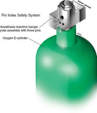
FIGURE 14-4 Pin index safety system for medical gas cylinders.
Additional measures exist to ensure appropriate oxygenation of the patient. Consider the scenario in which a fresh gas mixture of 50% oxygen and 50% nitrous oxide is being used and an isolated drop in oxygen pipeline pressure occurs. The sequence in which these two gases enter the fresh gas main line impacts the resulting gas mixture delivered to the patient. Oxygen is always the last gas to sequentially enter the fresh gas mixture to minimize (but not eliminate) the alteration in inspired oxygen (Fig. 14-5).
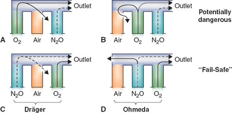
FIGURE 14-5 Flowmeter sequence—a potential cause of hypoxia. In the event of a flowmeter leak, a potentially dangerous arrangement exists when nitrous oxide is located in the downstream position (A,B). The safest configuration exists when oxygen is located in the downstream position (C,D). O2, oxygen; N2O, nitrous oxide. (From Riutort KT, Eisenkraft JB. The anesthesia workstation and delivery systems for inhaled anesthetics. In: Barash PB, Cullen BF, Stoelting RK, et al., eds. Clinical Anesthesia. 7th ed. Philadelphia: Lippincott Williams & Wilkins; 2013:641–696, with permission.)
Although inspection of the oxygen pipeline pressure gauge, a low O2 pressure alarm and low fraction of inspired oxygen (FiO2) concentration alarm would alert the user to the hazardous event described above, a mechanism known as the oxygen fail-safe system exists to minimize the decrement in FiO2. The fail-safe system proportionally decreases the flow of all other gases in use or halts their administration completely when a decline in oxygen pressure occurs. This prevents a disproportionate increase in the relative contribution of fresh gases that do not contribute to the oxygenation of the patient (1–3).

A properly functioning and calibrated oxygen analyzer is a mandatory part of the anesthesia workstation. There are several safeguards in modern machines to prevent delivery of a hypoxic gas mixture to the patient, but the oxygen analyzer is last in line and is the only device that actually measures the concentration.
Even under conditions in which the integrity of the oxygen pipeline source is maintained, it would still be possible to deliver a hypoxic fresh gas mixture to a patient. Imagine that oxygen flow is set to 1 L/min and nitrous oxide is delivered concurrently at 4 L/min. In this situation, the consequent FiO2 would be 20%, less than that of room air. Proportioning systems within the flowmeter assembly prevent exactly this type of problem from occurring. One possible design is the use of chain-linked sprockets that unite the control knobs for nitrous oxide and oxygen to each other. The effect imposes limits such that the ratio of nitrous oxide flow to oxygen flow never exceeds 3:1 (an FiO2 of 25%). Other types of proportioning mechanisms actively reduce nitrous oxide flows when oxygen flows are decreased by the user (1).
Lastly, an oxygen analyzer oversees the delivered concentration of oxygen just beyond the fresh gas outlet. Although not a constituent of the anesthesia machine per se, it is a final check on what concentration of oxygen is in fact ultimately being administered to the patient. Although the anesthesiologist cannot ascertain the functionality of the oxygen fail-safe system, he or she has an opportunity and a responsibility to certify the functionality of all of the safeguards just described (see “Anesthesia Workstation Preuse Checkout” later in this chapter).
D. Anesthetic Vaporizers
Commonly used volatile anesthetics are halogenated ether compounds that readily vaporize when exposed to the atmosphere. If kept in a closed container, the space above the liquid will contain molecules of these agents in the vapor state, equilibrating with the liquid surface. The pressure exerted against the walls of the container in this space by the gas-phase molecules is known as vapor pressure.
Related posts:


Stay updated, free articles. Join our Telegram channel

Full access? Get Clinical Tree


