Wissam Mustafa
The physics and engineering principles involved in electrical supply and electrical safety are very well established, although they may not be immediately or intuitively obvious. Many clinicians, as well as most citizens of developed countries, presume that the electrical supply will be present and equipment will be working safely every day. Little thought is given as to how this is achieved until a power system failure unexpectedly occurs. Furthermore, the terminology of electrical engineering is commonly misused by laypeople so that the meaning becomes imprecise or incorrect. For instance, during the course of a surgical procedure, many overlapping meanings for the word “ground” or “grounded” might be encountered, such as:
1. The physical surface of the Earth.
2. The voltage ascribed, by convention, to the Earth: 0 V.
3. Describing an electrical plug or socket that has three pins.
4. The green electrical wire, the ground lead, found within electrical power cables.
5. The adhesive pad that forms the dispersive return electrode for an electrosurgical unit.
6. The act of connecting a patient to some form of electrical apparatus such as the electrosurgical unit (“Is the patient grounded?”).
7. A state of failure of the operating room’s isolated electrical power system, in which the system “becomes grounded.”
Imagine the scenario of an anesthesiologist performing anesthesia for a shoulder arthroscopy in an ambulatory surgery center in which arthroscopic video cameras, instruments, and an electrosurgical unit are being used. A large puddle of joint irrigation solution has begun to accumulate on the floor and is spreading among cables on the floor and toward the anesthesiologist’s feet. Is the anesthesiologist safe? Now, imagine an anesthesiologist performing cardiac anesthesia emergently at night. While the patient is on bypass, the electrical safety monitors in the room begin to alarm. What should the anesthesiologist do? In order to respond appropriately in these and similar situations, it is necessary for the anesthesiologist to understand the electrical principles involved.
I. Principles of Electricity
A. Introduction
Electrical current (I, measured in amperes) will flow through an electrically conductive substance (a conductor) when there is a difference in electrical potential (E, measured in volts) across that conductor.
Therefore, if a person (being a potential conductor of electricity) touches a live domestic electrical wire (at, for example, 120 V) while in good contact with the ground (the person’s feet are at 0 V), electrical current will flow through the person and he or she will receive a shock. However, in the unlikely situation of a person standing on a metal plate that is at a voltage of 120 V while simultaneously touching a wire at a voltage of 120 V, no shock would be received because there would be no difference in voltage and no current would flow.
It is the difference in electrical potential (called the potential difference) that generates the current and the delivery of energy, not the absolute voltage. As an analogy, imagine two patients who accidentally fall from their beds. One patient is on the sixth floor of the hospital so his bed is 20 m above ground level; the other patient is on the third floor so his bed is 10 m above ground level. Of course, it is not the patients’ absolute height in the building (i.e., absolute voltage) that matters, but instead the height of the fall from their beds to the floor of their rooms (i.e., potential difference).
Conductors have a property called resistance (R, measured in ohms), which is their tendency to resist the flow of a current for a given potential difference. Potential difference, current, and resistance are related by Ohm’s law, represented with the following equation:

The electrical resistance of the human body is not constant; it depends strongly on the wetness of the skin, ranging from approximately 1,000 Ω with wet skin, to approximately 100,000 Ω with dry skin.
B. Direct and Alternating Current
The current flow in a circuit may be either direct current (DC) or alternating current (AC) depending on whether the direction of current flow in that circuit remains constant or oscillates. Batteries produce DC; the positive terminal of the battery remains at a constant higher electrical potential relative to the negative terminal of the battery until the battery is exhausted. The current always flows from the positive to the negative terminal. Conversely, as with common household electricity, the electrical current obtained from the “mains” power supply is AC; the potential difference of the live conductor oscillates around the neutral conductor. It is possible to convert AC to DC using a simple circuit called a rectifier, where AC voltages are specified in terms of the equivalent DC voltage that would make the same amount of electrical power available. The main power supply in the United States, which is nominally 120 V, actually has a live conductor whose potential difference oscillates sinusoidally between ±170 V relative to the neutral conductor 60 times each second. The frequency of AC oscillation is expressed in terms of Hertz (Hz); thus, common household current is 60 Hz.
C. Capacitors and Inductors, Reactance, and Impedance
Capacitors and inductors are both devices capable of storing electrical energy (1). A capacitor consists of two electrical plates, separated by an insulating material called the dielectric. As a DC voltage is applied to the capacitor, positive charge begins to accumulate on one plate of the capacitor, while negative charge begins to build up on the opposite plate. Eventually, a sufficient charge accumulates such that an equilibrium state is produced in which no further current can flow. The capacitor can be rapidly discharged from this state, producing a pulse of current through the desired part of the circuit. This is similar to how a camera flash operates. Once the capacitor is fully charged, however, no additional electrical current can flow onto it and its resistance to DC becomes effectively infinite. An inductor consists of a coil of wire wrapped in a spiral fashion around a ferromagnetic core. As electrical current passes through the coil of wire, an equal and opposing magnetic field is created in the core. An opposing electrical voltage occurs in the coil. In this regard, an inductor is similar to a simple electromagnet. However, once the current to the inductor is interrupted, the magnetic field in the core collapses, inducing a strong, opposing voltage spike in the electrical coil. From these simple analogies in DC, it can be seen that these devices can store charge and also cause electrical and magnetic fields that can exist beyond the physical boundaries of the device itself.

It is possible for electricity to be transmitted from one circuit to another without direct contact. This is an important part of the isolation transformer in use in most operating rooms.
When alternating current is applied to a capacitor, the voltage on the plates of the capacitor switches polarity as the AC voltage cycles. This causes electrical charge, in the form of electrical current, to flow on and off the plates of the capacitor. Therefore, even though there is no direct electrical connection between the two plates of the capacitor and the effective electrical resistance to DC is infinite, the act of repeatedly charging and discharging the capacitor allows alternating current to be able to flow through it. This “resistance” to alternating current is called reactance. It is a property of both capacitors and inductors and is dependent on the frequency of the alternating current. The simple and familiar expression of Ohm’s law, in which resistance is expressed as R, is only true for direct current. In order to model alternating current at different frequencies, a quantity called impedance is used. Impedance represents a combination of both resistance and reactance.
More precisely, impedance is a complex number whose real component is the electrical resistance and whose imaginary component is the reactance. From a practical standpoint, the existence of reactance makes it possible to design circuits that only allow electrical signals at certain frequencies to pass through them. This is the basis of, for example, graphic equalizers for music and medical signal filters for electrocardiograms (ECGs) that filter and amplify only those frequencies associated with cardiac conduction.
By carefully arranging capacitors and inductors, it is possible to design circuits that can receive and respond to external electromagnetic signals as well as to circuits that optimally radiate electromagnetic energy into the environment. Such circuits form the basis of radio reception and broadcasting. However, these properties can also exist in an unwanted form in electrical devices. For example, the proximity of electrical conductors within the power cord of a device or between the windings of an electric motor and its metal case, cause stray capacitance or parasitic capacitance. In turn, these produce the phenomena of electrical interference and leakage current.
II. Electrical Shock Hazards
A. Alternating and Direct Currents
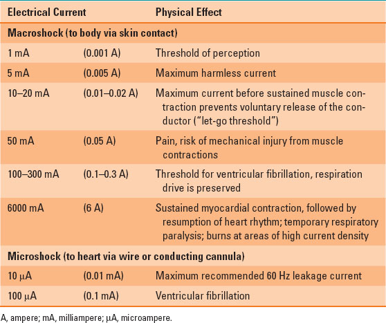
Electrical current can stimulate nerves and muscle contraction. This leads to the possibility of its therapeutic uses; however, it also leads to the risk of injury or death. Direct current is generally considered to be safer than alternating current. The amount of direct current necessary to induce ventricular fibrillation is around three times higher than the amount of alternating current required to produce the same effect. Table 43-1 summarizes the physical effects that are experienced from exposure to different thresholds of 60 Hz alternating current, as would be encountered in the standard US “mains” electricity supply.
Table 43-1 Physical Effects of Exposure to a 60 Hz Electrical Current, Measured in Amperes for 1 Second
The perception of the safety of direct current is reinforced by daily experience of “mains” alternating current being more powerful and dangerous than the relatively small amounts of direct current that are produced from standard batteries. However, a large direct current source such as an automobile battery or marine battery should not be considered harmless. The direct current discharge that can be produced between the terminals can cause significant burns and musculoskeletal injury.
B. Source of Shocks
Whenever a difference in electrical potential exists, current will flow through a suitable conductor placed between those electrical potentials. Consequently, there is always a risk of electrical shock whenever an external source of electricity is touched. The severity of the physical effect of the shock depends on both the magnitude of the electrical current and the duration of time for which that current is applied. At lower current levels, the electrical shock is first felt as a sensory tingling sensation, rising to pain with increased levels of current. Greater levels of current are able to stimulate contraction of muscles directly; furthermore, beyond a certain current level, it becomes impossible to release the contraction of these muscles voluntarily. Beyond this “let-go” threshold, it may no longer be possible for a victim to break contact with the source of electrical shock, further sustaining the electrical exposure (2). Further escalations in current can cause the onset of ventricular fibrillation as the electrical shock interferes with cardiac conduction and causes direct paralysis of the respiratory muscles. The flow of electrical current through the body also generates heat and can destroy tissue through direct thermal injury. The risk of burn injury is greatest at the points where the electrical current is entering or leaving the body, as the concentration of electrical current (the current density) is greatest there.
C. Grounding
When electrical current flows through a person, causing a shock, the current is usually flowing from some other electrical potential to ground. The body of the person is usually either in direct contact with the ground or electrically connected to the ground via a conductor such as an item of metal furniture. Because an electrical shock can only occur when there is a difference in electrical potential, the aim of electrical safety is to minimize that potential difference so that the magnitude of that electrical shock is made as small as possible. One approach, as seen in small battery-powered devices, is to minimize the total electrical voltage used by the device to such an extent that even the maximum possible shock current that could be generated by it is harmless. However, for devices that require significant electrical power, electrical safety must be achieved by more active means. In this case, “grounding” refers to the various steps that can be taken to reduce the magnitude of the possible electrical shock.
The simplest of these is illustrated in Figure 43-1
Related posts:


Stay updated, free articles. Join our Telegram channel

Full access? Get Clinical Tree


