Key Concepts
 Misuse of anesthesia gas delivery systems is three times more likely than failure of the device to cause equipment-related adverse outcomes. An operator’s lack of familiarity with the equipment or a failure to check machine function, or both, are the most frequent causes. These mishaps account for only about 2% of cases in the ASA Closed Claims Project database. The breathing circuit was the most common single source of injury (39%); nearly all damaging events were related to misconnects or disconnects.
 The anesthesia machine receives medical gases from a gas supply, controls the flow and reduces the pressure of desired gases to a safe level, vaporizes volatile anesthetics into the final gas mixture, and delivers the gases to a breathing circuit that is connected to the patient’s airway. A mechanical ventilator attaches to the breathing circuit but can be excluded with a switch during spontaneous or manual (bag) ventilation.
 Whereas the oxygen supply can pass directly to its flow control valve, nitrous oxide, air, and other gases must first pass through safety devices before reaching their respective flow control valves. These devices permit the flow of other gases only if there is sufficient oxygen pressure in the safety device and help prevent accidental delivery of a hypoxic mixture in the event of oxygen supply failure.
 Another safety feature of anesthesia machines is a linkage of the nitrous oxide gas flow to the oxygen gas flow; this arrangement helps ensure a minimum oxygen concentration of 25%.
 All modern vaporizers are agent specific and temperature corrected, capable of delivering a constant concentration of agent regardless of temperature changes or flow through the vaporizer.
 A rise in airway pressure may signal worsening pulmonary compliance, an increase in tidal volume, or an obstruction in the breathing circuit, tracheal tube, or the patient’s airway. A drop in pressure may indicate an improvement in compliance, a decrease in tidal volume, or a leak in the circuit.
 Traditionally ventilators on anesthesia machines have a double-circuit system design and are pneumatically powered and electronically controlled. Newer machines also incorporate microprocessor control that relies on sophisticated pressure and flow sensors. Some anesthesia machines have ventilators that use a single-circuit piston design.
 The major advantage of a piston ventilator is its ability to deliver accurate tidal volumes to patients with very poor lung compliance and to very small patients.
 Whenever a ventilator is used “disconnect alarms” must be passively activated. Anesthesia workstations should have at least three disconnect alarms: low pressure, low exhaled tidal volume, and low exhaled carbon dioxide.
 Because the ventilator’s spill valve is closed during inspiration, fresh gas flow from the machine’s common gas outlet normally contributes to the tidal volume delivered to the patient.
 Use of the oxygen flush valve during the inspiratory cycle of a ventilator must be avoided because the ventilator spill valve will be closed and the adjustable pressure-limiting (APL) valve is excluded; the surge of oxygen (600-1200 mL/s) and circuit pressure will be transferred to the patient’s lungs.
 Large discrepancies between the set and actual tidal volume are often observed in the operating room during volume-controlled ventilation. Causes include breathing circuit compliance, gas compression, ventilator-fresh gas flow coupling, and leaks in the anesthesia machine, the breathing circuit, or the patient’s airway.
 Waste-gas scavengers dispose of gases that have been vented from the breathing circuit by the APL valve and ventilator spill valve. Pollution of the operating room environment with anesthetic gases may pose a health hazard to surgical personnel.
 A routine inspection of anesthesia equipment before each use increases operator familiarity and confirms proper functioning. The U.S. Food and Drug Administration has made available a generic checkout procedure for anesthesia gas machines and breathing systems.
The Anesthesia Machine: Introduction
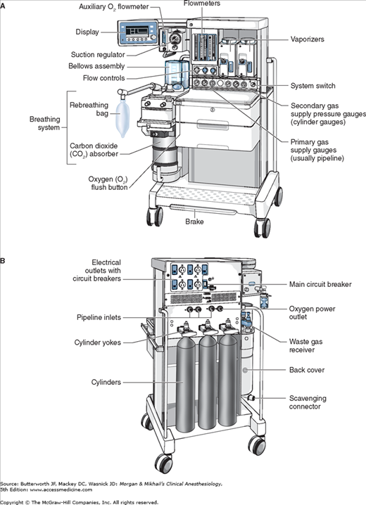
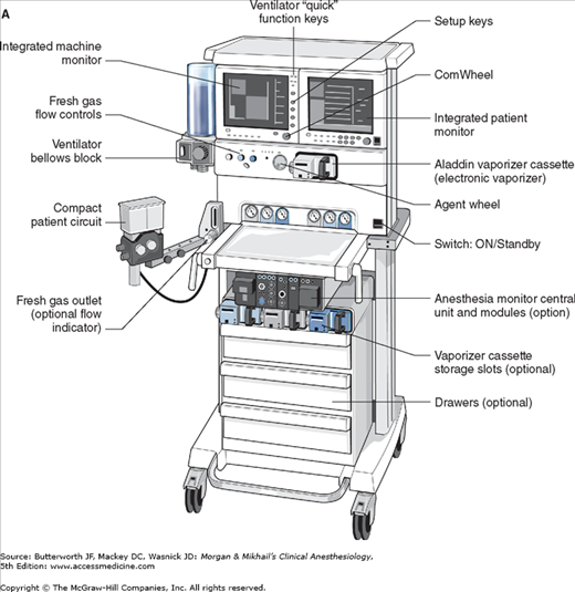
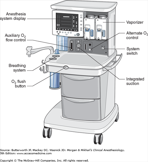
No piece of equipment is more intimately associated with the practice of anesthesiology than the anesthesia machine (Figure 4-1). On the most basic level, the anesthesiologist uses the anesthesia machine to control the patient’s ventilation and oxygen delivery and to administer inhalation anesthetics. Proper functioning of the machine is crucial for patient safety. Modern anesthesia machines have become very sophisticated, incorporating many built-in safety features and devices, monitors, and multiple microprocessors that can integrate and monitor all components. Additional monitors can be added externally and often still be fully integrated. Moreover, modular machine designs allow a wide variety of configurations and features within the same product line. The term anesthesia workstation is therefore often used for modern anesthesia machines. There are two major manufacturers of anesthesia machines in the United States, Datex-Ohmeda (GE Healthcare) and Dräger Medical. Other manufacturers (eg, Mindray) produce anesthesia delivery systems. Anesthesia providers should carefully review the operations manuals of the machines present in their clinical practice.
Much progress has been made in reducing the number of adverse outcomes arising from anesthetic gas delivery equipment, through redesign of equipment and education.  Misuse of anesthesia gas delivery systems is three times more likely than failure of the device to cause equipment-related adverse outcomes. Equipment misuse is characterized as errors in preparation, maintenance, or deployment of a device. Preventable anesthetic mishaps are frequently traced to an operator’s lack of familiarity with the equipment or a failure to check machine function, or both. These mishaps account for only about 2% of cases in the American Society of Anesthesiologists’ (ASA) Closed Claims Project database. The breathing circuit was the most common single source of injury (39%); nearly all damaging events were related to misconnects or disconnects. A misconnect was defined as a nonfunctional and unconventional configuration of breathing circuit components or attachments. In decreasing frequency, other causes involved vaporizers (21%), ventilators (17%), and oxygen supply (11%). Other more basic components of the anesthesia machine (eg, valves) were responsible in only 7% of cases. All malpractice claims in the database that involved the anesthesia machine, oxygen supply tanks or lines, or ventilators occurred before 1990; since then claims involving breathing circuits and vaporizers have continued to occur.
The American National Standards Institute and subsequently the ASTM International (formerly the American Society for Testing and Materials, F1850-00) published standard specifications for anesthesia machines and their components. Table 4-1 lists essential features of a modern anesthesia workstation. Changes in equipment design have been directed at minimizing the probability of breathing circuit misconnects and disconnects and automating machine checks. Because of the durability and functional longevity of anesthesia machines, the ASA has developed guidelines for determining anesthesia machine obsolescence (Table 4-2). This chapter is an introduction to anesthesia machine design, function, and use.
| Essential Features | Purpose |
|---|---|
| Noninterchangeable gas-specific connections to pipeline inlets (DISS)1 with pressure gauges, filter, and check valve | Prevent incorrect pipeline attachments; detect failure, depletion, or fluctuation |
| Pin index safety system for cylinders with pressure gauges, and at least one oxygen cylinder | Prevent incorrect cylinder attachments; provide backup gas supply; detect depletion |
| Low oxygen pressure alarm | Detect oxygen supply failure at the common gas inlet |
| Minimum oxygen/nitrous oxide ratio controller device (hypoxic guard) | Prevent delivery of less than 21% oxygen |
| Oxygen failure safety device (shut-off or proportioning device) | Prevent administration of nitrous oxide or other gases when the oxygen supply fails |
| Oxygen must enter the common manifold downstream to other gases | Prevent hypoxia in event of proximal gas leak |
| Oxygen concentration monitor and alarm | Prevent administration of hypoxic gas mixtures in event of a low-pressure system leak; precisely regulate oxygen concentration |
| Automatically enabled essential alarms and monitors (eg, oxygen concentration) | Prevent use of the machine without essential monitors |
| Vaporizer interlock device | Prevent simultaneous administration of more than one volatile agent |
| Capnography and anesthetic gas measurement | Guide ventilation; prevent anesthetic overdose; help reduce awareness |
| Oxygen flush mechanism that does not pass through vaporizers | Rapidly refill or flush the breathing circuit |
| Breathing circuit pressure monitor and alarm | Prevent pulmonary barotrauma and detect sustained positive, high peak, and negative airway pressures |
| Exhaled volume monitor | Assess ventilation and prevent hypo- or hyperventilation |
| Pulse oximetry, blood pressure, and ECG monitoring | Provide minimal standard monitoring |
| Mechanical ventilator | Control alveolar ventilation more accurately and during muscle paralysis for prolonged periods |
| Backup battery | Provide temporary electrical power (>30 min) to monitors and alarms in event of power failure |
| Scavenger system | Prevent contamination of the operating room with waste anesthetic gases |
Unacceptable features
|
Undesirable features
|
Overview
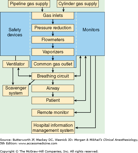
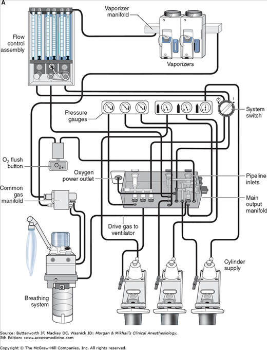
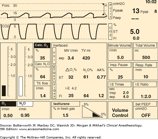
 In its most basic form, the anesthesia machine receives medical gases from a gas supply, controls the flow and reduces the pressure of desired gases to a safe level, vaporizes volatile anesthetics into the final gas mixture, and delivers the gases to a breathing circuit connected to the patient’s airway (Figures 4-2 and 4-3). A mechanical ventilator attaches to the breathing circuit but can be excluded with a switch during spontaneous or manual (bag) ventilation. An auxiliary oxygen supply and suction regulator are also usually built into the workstation. In addition to standard safety features (Table 4-1) top-of-the-line anesthesia machines have additional safety features, enhancements, and built-in computer processors that integrate and monitor all components, perform automated machine checkouts, and provide options such as automated record-keeping and networking external monitors and hospital information systems (Figure 4-4). Some machines are designed specifically for mobility, magnetic resonance imaging (MRI) compatibility or compactness.

Gas Supply
Most machines have gas inlets for oxygen, nitrous oxide, and air. Compact models often lack air inlets, whereas other machines may have a fourth inlet for helium, heliox, carbon dioxide, or nitric oxide. Separate inlets are provided for the primary pipeline gas supply that passes through the walls of health care facilities and the secondary cylinder gas supply. Machines therefore have two gas inlet pressure gauges for each gas: one for pipeline pressure and another for cylinder pressure.
Oxygen and nitrous oxide (and often air) are delivered from their central supply source to the operating room through a piping network. The tubing is color coded and connects to the anesthesia machine through a noninterchangeable diameter-index safety system (DISS) fitting that prevents incorrect hose attachment. The noninterchangeability is achieved by making the bore diameter of the body and that of the connection nipple specific for each supplied gas. A filter helps trap debris from the wall supply and a one-way check valve prevents retrograde flow of gases into the pipeline supplies. It should be noted that most modern machines have an oxygen (pneumatic) power outlet that may be used to drive the ventilator or provide an auxiliary oxygen flowmeter. The DISS fittings for the oxygen inlet and the oxygen power outlet are identical and should not be mistakenly interchanged. The approximate pipeline pressure of gases delivered to the anesthesia machine is 50 psig.
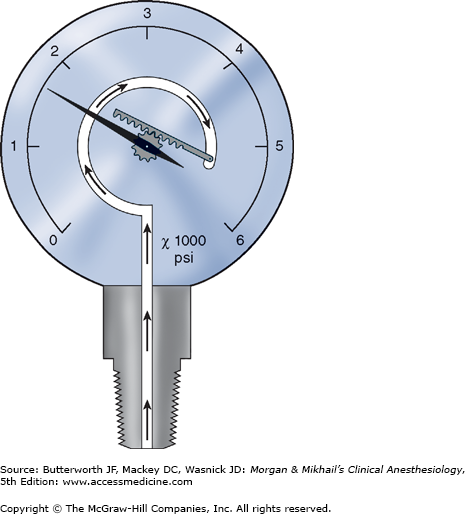
Cylinders attach to the machine via hanger-yoke assemblies that utilize a pin index safety system to prevent accidental connection of a wrong gas cylinder. The yoke assembly includes index pins, a washer, a gas filter, and a check valve that prevents retrograde gas flow. The gas cylinders are also color-coded for specific gases to allow for easy identification. In North America the following color-coding scheme is used: oxygen = green, nitrous oxide = blue, carbon dioxide = gray, air = yellow, helium = brown, nitrogen = black. In the United Kingdom, white is used for oxygen and black and white for air. The E-cylinders attached to the anesthesia machine are a high-pressure source of medical gases and are generally used only as a back-up supply in case of pipeline failure. Pressure of gas supplied from the cylinder to the anesthesia machine is 45 psig. Some machines have two oxygen cylinders so that one cylinder can be used while the other is changed. At 20°C, a full cylinder contains 600 L of oxygen at a pressure of 1900 psig, and 1590 L of nitrous oxide at 745 psig. Cylinder pressure is usually measured by a Bourdon pressure gauge (Figure 4-5). A flexible tube within this gauge straightens when exposed to gas pressure, causing a gear mechanism to move a needle pointer.
Flow Control Circuits
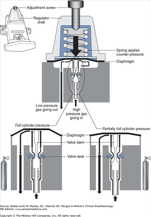
Unlike the relatively constant pressure of the pipeline gas supply, the high and variable gas pressure in cylinders makes flow control difficult and potentially dangerous. To enhance safety and ensure optimal use of cylinder gases, machines utilize a pressure regulator to reduce the cylinder gas pressure to 45-47 psig1 before it enters the flow valve (Figure 4-6). This pressure, which is slightly lower than the pipeline supply, allows preferential use of the pipeline supply if a cylinder is left open (unless pipeline pressure drops below 45 psig). After passing through Bourdon pressure gauges and check valves, the pipeline gases share a common pathway with the cylinder gases. A high-pressure relief valve provided for each gas is set to open when the supply pressure exceeds the machine’s maximum safety limit (95-110 psig), as might happen with a regulator failure on a cylinder. Some machines also use a second regulator to drop both pipeline and cylinder pressure further (two-stage pressure regulation). A second-stage pressure reduction may also be needed for an auxiliary oxygen flowmeter, the oxygen flush mechanism, or the drive gas to power a pneumatic ventilator.
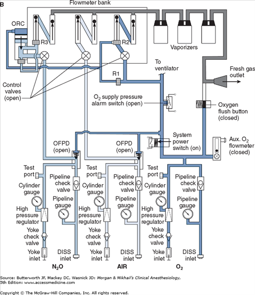
 Whereas the oxygen supply can pass directly to its flow control valve, nitrous oxide, air (in some machines), and other gases must first pass through safety devices before reaching their respective flow control valves. In other machines, air passes directly to its flow control valve; this allows administration of air even in the absence of oxygen. These devices permit the flow of other gases only if there is sufficient oxygen pressure in the safety device and help prevent accidental delivery of a hypoxic mixture in the event of oxygen supply failure. Thus in addition to supplying the oxygen flow control valve, oxygen from the common inlet pathway is used to pressurize safety devices, oxygen flush valves, and ventilator power outlets (in some models). Safety devices sense oxygen pressure via a small “piloting pressure” line that may be derived from the gas inlet or secondary regulator. In some anesthesia machine designs (eg, Datex-Ohmeda Excel), if the piloting pressure line falls below a threshold (eg, 20 psig), the shut-off valves close, preventing the administration of any other gases. The terms fail-safe and nitrous cut-off were previously used for the nitrous oxide shut-off valve.
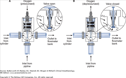
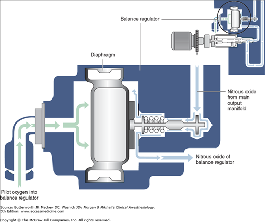
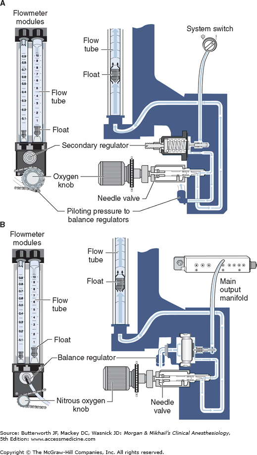
Most modern (particularly Datex-Ohmeda) machines use a proportioning safety device instead of a threshold shut-off valve. These devices, called either an oxygen failure protection device (Dräger) or a balance regulator (Datex-Ohmeda), proportionately reduce the pressure of nitrous oxide and other gases except for air (Figures 4-7 and 4-8). They completely shut off nitrous oxide and other gas flow only below a set minimum oxygen pressure (eg, 0.5 psig for nitrous oxide and 10 psig for other gases).
All machines also have an oxygen supply low-pressure sensor that activates alarm sounds when inlet gas pressure drops below a threshold value (usually 20-30 psig). It must be emphasized that these safety devices do not protect against other possible causes of hypoxic accidents (eg, gas line misconnections), in which threshold pressure may be maintained by gases containing inadequate or no oxygen.
Once the pressure has been reduced to a safe level, each gas must pass through flow control valves and is measured by flowmeters before mixing with other gases, entering the active vaporizer, and exiting the machine’s common gas outlet. Gas lines proximal to flow valves are considered to be in the high-pressure circuit whereas those between the flow valves and the common gas outlet are considered part of the low-pressure circuit of the machine. When the knob of the flow control valve is turned counterclockwise, a needle valve is disengaged from its seat, allowing gas to flow through the valve (Figure 4-9). Stops in the full-off and full-on positions prevent valve damage. Touch- and color-coded control knobs make it more difficult to turn the wrong gas off or on. As a safety feature the oxygen knob is usually fluted, larger, and protrudes farther than the other knobs. The oxygen flowmeter is positioned furthest to the right, downstream to the other gases; this arrangement helps to prevent hypoxia if there is leakage from a flowmeter positioned upstream.
Flow control knobs control gas entry into the flowmeters by adjustment via a needle valve. Flowmeters on anesthesia machines are classified as either constant-pressure variable-orifice (rotameter) or electronic. In constant-pressure variable-orifice flowmeters, an indicator ball, bobbin, or float is supported by the flow of gas through a tube (Thorpe tube) whose bore (orifice) is tapered. Near the bottom of the tube, where the diameter is small, a low flow of gas will create sufficient pressure under the float to raise it in the tube. As the float rises, the (variable) orifice of the tube widens, allowing more gas to pass around the float. The float will stop rising when its weight is just supported by the difference in pressure above and below it. If flow is increased, the pressure under the float increases, raising it higher in the tube until the pressure drop again just supports the float’s weight. This pressure drop is constant regardless of the flow rate or the position in the tube and depends on the float weight and tube cross-sectional area.
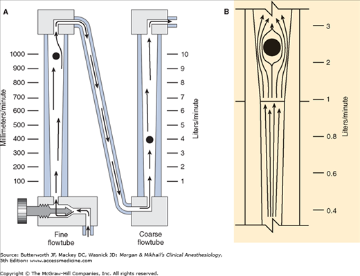
Flowmeters are calibrated for specific gases, as the flow rate across a constriction depends on the gas’s viscosity at low laminar flows (Poiseuille’s law) and its density at high turbulent flows. To minimize the effect of friction between them and the tube’s wall, floats are designed to rotate constantly, which keeps them centered in the tube. Coating the tube’s interior with a conductive substance grounds the system and reduces the effect of static electricity. Some flowmeters have two glass tubes, one for low flows and another for high flows (Figure 4-10A); the two tubes are in series and are still controlled by one valve. A dual taper design can allow a single flowmeter to read both high and low flows (Figure 4-10B). Causes of flowmeter malfunction include debris in the flow tube, vertical tube misalignment, and sticking or concealment of a float at the top of a tube.
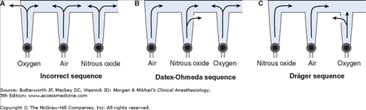
Should a leak develop within or downstream from an oxygen flowmeter, a hypoxic gas mixture can be delivered to the patient (Figure 4-11). To reduce this risk, oxygen flowmeters are always positioned downstream to all other flowmeters (nearest to the vaporizer).
Some anesthesia machines have electronic flow control and measurement (Figure 4-12). In such instances, a back-up conventional (Thorpe) auxiliary oxygen flowmeter is provided. Other models have conventional flowmeters but electronic measurement of gas flow along with Thorpe tubes and digital or digital/graphic displays (Figure 4-13). The amount of pressure drop caused by a flow restrictor is the basis for measurement of gas flow rate in these systems. In these machines oxygen, nitrous oxide, and air each have a separate electronic flow measurement device in the flow control section before they are mixed together. Electronic flowmeters are essential components in workstations if gas flow rate data will be acquired automatically by computerized anesthesia recording systems.
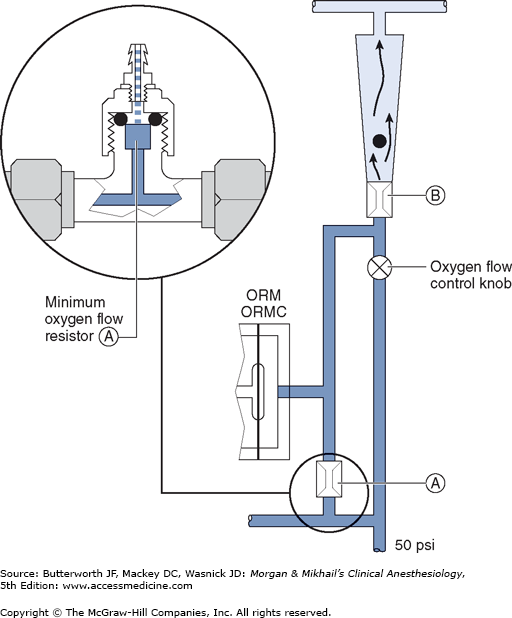
The oxygen flow valves are usually designed to deliver a minimum flow of 150 mL/min when the anesthesia machine is turned on. One method involves the use of a minimum flow resistor (Figure 4-14). This safety feature helps ensure that some oxygen enters the breathing circuit even if the operator forgets to turn on the oxygen flow. Some machines are designed to deliver minimum flow or low-flow anesthesia (<1 L/min) and have minimum oxygen flows as low as 50 mL/min.
 Another safety feature of anesthesia machines is a linkage of the nitrous oxide gas flow to the oxygen gas flow; this arrangement helps ensure a minimum oxygen concentration of 25%. The oxygen/nitrous oxide ratio controller links the two flow valves either pneumatically or mechanically. To maintain the minimum oxygen concentration, the system (Link-25) in Datex-Ohmeda machines increases the flow of oxygen, whereas the oxygen ratio monitor controller (ORMC) in Dräger machines reduces the concentration of nitrous oxide. It should be noted that this safety device does not affect the flow of a third gas (eg, air, helium, or carbon dioxide).
Volatile anesthetics (eg, halothane, isoflurane, desflurane, sevoflurane) must be vaporized before being delivered to the patient. Vaporizers have concentration-calibrated dials that precisely add volatile anesthetic agents to the combined gas flow from all flowmeters. They must be located between the flowmeters and the common gas outlet. Moreover, unless the machine accepts only one vaporizer at a time, all anesthesia machines should have an interlocking or exclusion device that prevents the concurrent use of more than one vaporizer.
At temperatures encountered in the operating room, the molecules of a volatile anesthetic in a closed container are distributed between the liquid and gaseous phases. The gas molecules bombard the walls of the container, creating the saturated vapor pressure of that agent. Vapor pressure depends on the characteristics of the volatile agent and the temperature. The greater the temperature, the greater the tendency for the liquid molecules to escape into the gaseous phase and the greater the vapor pressure (Figure 4-15). Vaporization requires energy (the latent heat of vaporization), which results in a loss of heat from the liquid. As vaporization proceeds, temperature of the remaining liquid anesthetic drops and vapor pressure decreases unless heat is readily available to enter the system. Vaporizers contain a chamber in which a carrier gas becomes saturated with the volatile agent.
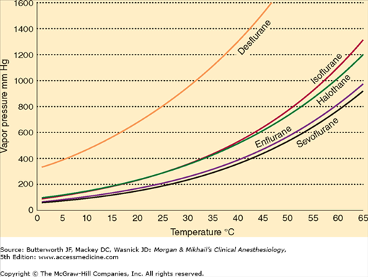
A liquid’s boiling point is the temperature at which its vapor pressure is equal to the atmospheric pressure. As the atmospheric pressure decreases (as in higher altitudes), the boiling point also decreases. Anesthetic agents with low boiling points are more susceptible to variations in barometric pressure than agents with higher boiling points. Among the commonly used agents, desflurane has the lowest boiling point (22.8°C at 760 mm Hg).
Related posts:

Stay updated, free articles. Join our Telegram channel

Full access? Get Clinical Tree


