Shock and Electrocution
Gordon L. Gibby
CASE SUMMARY
Standing on a wet surface and intent on an urgent task, a 50-year-old anesthesiologist’s arm brushed against an electric device. Instantly, the physician received a powerful electric shock, which could have been fatal had the contact been slightly more forceful. Not so lucky was a 19-year-old New Jersey pool lifeguard who fell to the ground, touching the housing of a swimming pool pump. Coworkers were unable to touch the electrified victim, who died as they watched. Both true incidents involved items that, surprisingly, can be found in any modern operating room: A nonisolated power system, no ground-fault circuit interrupter, a broken ground wire, and a miswired electric device. This chapter will explain practical steps that can be taken to reduce the chances of becoming a statistic.
The typical anesthesiologist may wonder why so much emphasis is placed on electric safety. Enormous effort has gone into the creation of national electric wiring standards, low leakage equipment design, ground-fault interruption systems, isolated power systems, doubleinsulated equipment, and isolated patient leads, all in an attempt to increase electric safety. Why? Perhaps the reason for the sheer magnitude of the effort is that electrocution is a uniquely stealthy, insidious, and pervasive risk in our highly electrified society. Other common, everyday risks are usually obvious. The noise and blur of traffic warns the pedestrian not to stray off the sidewalk; the downward glance from a height and the nearby edge makes obvious the risk of falling; the glowing hot plate and its radiant warmth gives warning of the potential for a serious burn. However, the simple metal cover on an electric device in an operating room sits silently still, emitting no warning to any of our five senses that it has become electrified by a wiring fault, and now is connected to a source of voltage sufficient to cause ventricular fibrillation. Instantaneously on contact, if entry and exit sites are such that sufficient current flows through the arms and chest, the unsuspecting victim may be unable to let go, unable to move under control, no longer able to breathe, and in ventricular fibrillation. This risk comes from the ability of electricity to excite neural and muscular tissues; the risk of burns is also present because of the heating that can be caused by large currents in tissues. An outcome so terrible, and a risk so impossible to detect with the normal human senses has caused such carefully thought-out safety measures to be employed for decades to contain the risk of electrocution in health care settings.
Historically, anesthesiologists are very familiar with stealthy risks. In earlier decades, a similar situation was present for the risk of instantaneous explosion due to ignition of flammable anesthetics, which likewise resulted in extensive safety precautions and eventual abandonment of such agents when safer, nonexplosive ones became available. There is no apparent replacement for electricity, and the risk is not only to the unconscious patient under anesthesia but in fact extends to the anesthesiologist and all other personnel in the operating room. With no likely alternative, it is prudent to carefully understand the mechanisms of harm due to electricity, all the safety systems required or suggested to reduce that risk, and to be able to detect when those safety barriers have been breached by accident or lack of knowledge. Although this chapter begins with a discussion of electrocutions, it will also cover several other electrically related risks, including burns and electromagnetic interference (EMI) to electronic equipment in the health care setting. Anesthesiologists frequently must interface with administrators on issues of construction and equipment; information on national standards (including their weak points) and rationales appropriate to those discussions is also included. Such knowledge will allow the anesthesiologists not only to protect their patients but also themselves and their colleagues.
What Are the Statistics on the Incidence of Electrocutions in the United States?
▪ INCIDENCE
Fortunately, the number of electrocutions annually in the United States is not large. Data from the Consumer
Product Safety Counsel indicates that in the United States during the decade from 1989 to 1998, an average of 573 persons were electrocuted annually from all causes. In 227 (approximately 40%), electrocution involved a consumer product.1 Contact with overhead power lines is responsible for another 40%.2 It is estimated that another 800 persons die annually in the United States from fires caused by faulty electric systems, and $1.2 billion in property damage results from faulty use of electricity.3
Product Safety Counsel indicates that in the United States during the decade from 1989 to 1998, an average of 573 persons were electrocuted annually from all causes. In 227 (approximately 40%), electrocution involved a consumer product.1 Contact with overhead power lines is responsible for another 40%.2 It is estimated that another 800 persons die annually in the United States from fires caused by faulty electric systems, and $1.2 billion in property damage results from faulty use of electricity.3
▪ SOURCES
Simple devices such as kitchen appliances and extension cords are among the most common items to cause electrocutions in the home. Anesthesiologists work with small electric devices continuously, with electric cords going everywhere; they work with liquids and in wet conditions. They should be concerned about electric shock! Surprisingly, economic interests are a factor in driving the operating room environment to become somewhat less protected against electrocution than the modern kitchen. These changes also should be a matter of concern to anesthesiologists, who in recent decades have not often been greatly concerned about their own risk of being injured by electricity.
What Are the Basic Facts on Shock and Electrocution, and How Do They Occur?
Electricity always moves in circles, namely, in complete circuits; if it did not, electrons in prodigious quantities would “pile up” rapidly wherever they stopped moving. A direct current [dc or DC] of 1 ampere [A] [analogous to that of a 100 W light bulb] would pile up more than 6 × 10¹⁸ electrons in 1 second if it did not continue flowing back to the source. A useful voltage source must therefore always have not one but two terminals or connections. Current will flow only if something touches both of those connections, so that a complete circuit is made, as shown in Figure 55.1. Preventing electrocution is conceptually quite simple: Prevent the human body from ever making simultaneous contact with both of those connections, so that current cannot pass through the body, and in particular, cannot pass through the heart (giving rise to ventricular fibrillation). Just as eagles can rest safely perched on one high voltage wire, but are instantly electrocuted if a long-spread wing touches the second wire, the anesthesiologist or patient is safe as long as they never make two connections to an electric circuit. All the safety standards and conventions are designed to make at least the second connection unlikely, and some make even the first connection more difficult.
▪ CURRENTS AND VOLTAGE
Electricity has different effects depending on how great the current is flowing, whether it is a DC or alternating (ac or AC) current, and the frequency (if AC) and through which organs it passes. Small amounts of current flowing into the hand through the skin, 1 to 10 milliamperes (mA), may be perceived as a shock or tingle; lower currents through skin may be imperceptible. Every anesthesiologist is quite familiar with the effects of ACs of 20 to 80 mA at approximately 100 Hz delivered to the ulnar nerve by the neuromuscular blockade twitch monitor; sustained currents of this strength and frequency cause tetanus (inability to let go of the item). DCs tend to cause sudden contraction of all affected muscles; the resulting jerk often frees the victim from the source. Anesthesiologists are familiar with the strong movements caused by DC defibrillation (several amperes for a brief period of time) delivered across the chest. ACs approximately 100 mA (100 mA, or 0.1 A) that enter through the skin and pass through the heart may cause ventricular fibrillation and paralysis of breathing (similar to the tetanus of the ulnar nerve). Currents of many amperes can cause burns, as seen in power line burn victims.
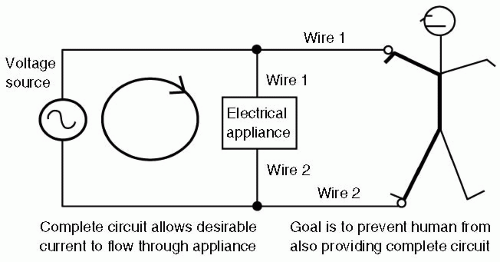 FIGURE 55.1 Two connections are required to deliver power to an electric appliance. Likewise, two connections are required to harm a person. Preventing either connection can save the potential victim. Best plan is to prevent both where possible. |
As delivered from the convenient wall outlet (receptacle), electricity is in the form of AC, which oscillates in its direction of flow forward and backward 60 times per second (60 Hz). The frequency of AC is an important determinant of its electrocution danger (but not its burn potential). As George Westinghouse successfully argued in the late 1800s, 60 -Hz AC is optimal in an economic sense for delivery of electricity. It allows convenient stepup of the voltage (by transformers), making it possible for long-distance power lines to use relatively small (less expensive) copper wire. It also allows easy step-down of the voltage to deliver lower voltages to the home or business (also by transformers), all with minimal heating losses in the transformers. However, Edison was correct in arguing that this frequency is among the most dangerous to mankind in terms of risk of electrocution. As noted, approximately 60 Hz AC of 100 mA (roughly one tenth that flowing through a typical 100-W lamp) flowing through the chest can cause fibrillation. DC, championed unsuccessfully by Edison, does not nearly so often cause ventricular fibrillation and, in fact, is used by most defibrillators to stop ventricular fibrillation with a shock that allows resetting of all the electric activity in the heart. Mammals’ hearts are most vulnerable to AC at frequencies above
5 Hz and up to approximately 200 Hz; the vulnerability then declines significantly with increasing frequency. Radio frequencies are of little electrocution risk because they reverse direction in microseconds or nanoseconds, giving biologic membranes little time to respond. The relative safety of high-frequency current, used today in electrocautery, was known to Nikola Tesla in the late 1800s. He often used his own body as one wire of a circuit harmlessly conducting high frequency current through noble gas-filled bottles, similar to today’s fluorescent lamps. The current would light up the noble gas, but would not fibrillate Tesla, nor burn him as long as he gripped with a large enough surface area.
5 Hz and up to approximately 200 Hz; the vulnerability then declines significantly with increasing frequency. Radio frequencies are of little electrocution risk because they reverse direction in microseconds or nanoseconds, giving biologic membranes little time to respond. The relative safety of high-frequency current, used today in electrocautery, was known to Nikola Tesla in the late 1800s. He often used his own body as one wire of a circuit harmlessly conducting high frequency current through noble gas-filled bottles, similar to today’s fluorescent lamps. The current would light up the noble gas, but would not fibrillate Tesla, nor burn him as long as he gripped with a large enough surface area.
▪ MACROSHOCK VERSUS MICROSHOCK
Macroshock is the name given to the type of electrocution where electricity enters through the skin and flows through a substantial portion of the body, only a fraction actually going through the heart. Most electric standards and practices are designed to protect people from macroshock, because macroshock is an ever-present hazard to anyone, and possible in any location served by electricity.
A new and different risk scenario developed when monitoring catheters, pacing wires, and dye injection catheters first began to be utilized inside the heart or the coronary arteries. Electricity conducted directly to the heart was much more concentrated; far smaller levels of current could cause fibrillation. This type of hazard was named microshock and is different from macroshock in two ways: (i) it only occurs when an electric connection directly to the heart is possible, hence in a small subset of patients and (ii) it can be caused by such a smaller amount of current (as little as a few tens of microamperes).4 Microshock requires a different sort of prevention. Standard protection techniques to prevent whole-body electrocution are woefully inadequate to prevent direct cardiac fibrillation in these special cases. However, the solution needs to be applied to a smaller subset of equipment because fewer devices are connected to pulmonary artery or dye injection catheters, or to pacing wires. A new standard for safe leakage current from patient connections, such as electrocardiogram (ECG) leads and pressure transducers, to prevent microshock was established at 10 µA (a very low level of leakage). In vivo experimental work on microshock thresholds supports this choice of safe leakage current. Dye injection catheters of 6 to 8 French size, similar to pulmonary artery catheters used by anesthesiologists, have end-holes from 0.6 to 3.14 mm2; pacing catheters have much larger surface areas, ranging from 10 to 90 mm2. While pacing catheters offer a low-resistance wire directly to the heart (as would atrial pacing electrodes left in postoperatively as well), the saline conducting column of a small dye injection catheter (analogous to a simple intracardiac catheter) offers a resistance in the megohm range. Only 10 V is required to drive 10 µA through 1 megohm. The most sensitive area of the heart for causing rhythm disturbances is the apex of the right ventricle, which is also the usual position for pacing catheters.5 Fibrillation thresholds were not related to a fixed current density, and threshold levels were not affected by the size of the dog over a heart size range of 300%. Smaller catheter areas required somewhat greater current density but lower total current; therefore there was not a fixed minimum current density nor a fixed minimum current required. The smallest catheters required total currents of <25 µA to cause fibrillation. Pump failure was even more easily produced, and when currents lasted for >15 seconds, effective pumping could be abolished by currents roughly half that required for fibrillation. The authors concluded that 10 µA was certainly not too low a safety standard, and that a number of fatalities could be expected if it were lifted to even 50 to 60 µA.5
To protect against this microshock risk, ECG and other monitoring equipments that directly touch the patient electrically and can be connected to central catheters or pacing wires on occasion have been redesigned to have isolated inputs. Equipment designers developed amplifier techniques using special transformers or optically coupled isolators to electrically separate patient leads from the remainder of the monitor’s electronics. High resistance intentionally placed in series with the input wires also reduces the risk by dramatically reducing the current that can flow with typical voltages. These developments have successfully protected patients from microshock. However, anesthesiologists must still be exceptionally careful while handling direct cardiac pacing wires, which are exquisitely sensitive to applied voltages. Starmer et al. noted that they could easily cause ventricular fibrillation in dogs by merely touching the wet catheter or metallic clip lead on a catheter (e.g., used to connect it to an ECG V-lead) and touching a “grounded” piece of equipment with the other hand. Bare cardiac wires should always remain protected by insulating coverings and handled with insulated (gloved) hands.6
It is important to emphasize that the amount of current needed to cause death (through ventricular fibrillation or cessation of pumping) through a direct connection to the heart is so exceedingly small that it cannot be prevented by gross shock prevention strategies such as circuit breakers, grounded equipment chassis, or even isolated power systems or ground-fault interrupters. The allowable equipment leakage (100 µA) into the ground wire is sufficient to easily cause microshock. The only effective strategy to prevent microshock involves exquisite care in keeping intracardiac conductors insulated when not in use, and allowing them only to be connected to safe equipment such as battery operated pacemakers, isolatedinput ECG machines, and similar equipment designed with microshock prevention. All of the remaining protection systems are designed to prevent macroshock because this is a hazard to all patients and personnel, whereas microshock is a risk only to the small fraction of patients with a direct cardiac electrode. It is a fallacy to discount the validity of useful protections against macroshock (as discussed in the subsequent text) merely because these protections are ineffective against microshock.
What Are the Risks of Macroshock, and How Can It Be Prevented?
▪ RISKS
Although microshock has been effectively addressed by the development of patient-isolated monitors, the hospital and operating room are busy places where wires and equipment are in daily clinical use and can break and potentially cause macroshock. Except for electric monitoring devices, such as ECG or electroencephalogram (EEG) monitors that intentionally touch the patient with patient-isolated conductors, it is almost a universal standard that electric devices close up their wiring behind a cabinet or case and only extend low voltage (and insulated) wires to such devices as keyboard, mouse, or pulse oximeter probe. This is to prevent users or patients from making the two necessary connections to a high voltage AC source to be harmed. The significance of the high voltage AC source must be emphasized. Much of modern computerized and transistorized equipment operates with such low (and, safer, DC) voltages that there is little risk of macroshock—even if the user placed their hand right onto the circuit board! Computer designers are continuously reducing computer internal operating voltages in an attempt to make microprocessors run cooler and last longer on battery power. For many types of equipment today, the major risk of macroshock is primarily the path of 120-V AC wall supply current from receptacle to the inside of the chassis, ending at the point that it is converted by transformer to a lower voltage. This risk is likely to continue, because changing wall receptacles to a lower voltage would require far heavier (more expensive) wiring to supply the high power needs of heating, cooling, and mechanical devices both at home and in the operating room.
Therefore, the continued presence of the 120-V AC power system means that macroshock will remain a risk. One hundred and twenty volts AC is sufficiently large to present an electrocution risk to any person becoming part of a complete circuit. Damaged power cords then unsurprisingly lead the list of possible connection points for victims, with additional risks from loose wiring or circuitry breakdowns inside the equipment. Therefore, macroshock prevention focuses squarely on the power wiring of the operating room, because this is the single, greatest remaining source of potentially electrocuting voltage.
Ground
When discussing macroshock electrocution risks and prevention, perhaps the most confusing topic is that of “ground.” The confusion is understandable. The user is told that certain power sources are not connected to the ground (earth), which is for the purpose of safety, yet all electric equipment is purposely connected to ground, and this is also supposedly for safety. Standing on wet ground is said to be risky, although other power systems are said to be grounded—how can this be safer? Certain devices are even named in ways that suggest they check for some error in the “ground”, as they are named groundfault interrupters. The word “ground” is certainly used in confusing ways!
An examination of the use of the ground in the field of electricity is in order. The earth is of course the largest and most readily available electric conductor of all. It is a low resistance conductor, to which a low resistance connection can be made by driving a long metal rod or pipe into the ground to create a significant surface area of connection to moist soil. (Before the popularity of polyvinyl chloride [PVC] plumbing, the readily available metallic cold water pipe sufficed for most needs.) Because the earth does connect distant cities by a low resistance, it can be used as one of the two conductors necessary to transport an electric current to, say, a distant telegraph. Furthermore, because of capacitance, long-distance electric systems such as power lines are unavoidably somewhat connected to the earth or ground.
This point—the capacitance of large electric power lines to the earth—requires further discussion. It is the key to understanding much of the confusion about ground. Capacitance exists between any two conductors that have surface areas separated by an insulator, that is, are not connected to each other. The larger the surface areas and the closer the conductors (still without touching), the larger is the capacitance. Capacitance refers to the ability of the two conductors to store up a charge difference, negative charges building up on one conductor and positive on the other, when a voltage is impressed upon them. AC (used by most electric distribution systems) is able to alternately push current into a capacitor, that is charge it, first one way and then another, and give the impression—and an actual outwardly visible effect—of current crossing the capacitor (see Fig. 55.2). This is in contrast to DC electricity, which after charging up the plates of the capacitor can cause no further flow of current. Because large electric distribution transmission lines have large total surface area and are separated from the earth, they form a capacitor with the earth. And although the capacitance is not great (because of the relatively large distance between the transmission lines and the earth), the extraordinarily high voltages involved can drive a current through that capacitance that is quite dangerous to humans. This means that, effectively, all transmission lines are to some extent “connected” to the earth regardless of whether we actually drive a stake into the ground and clamp one wire to it. The exact voltage difference between the earth and the transmission line is complex and difficult to predict if both lines are insulated from the earth, and therefore both forming a capacitor to it. In this situation, both wires are said to be “floating” at an unknown potential (voltage) with respect to the earth. This means that a human touching the earth (e.g., merely standing on it with imperfectly insulating shoes)
must regard any transmission line with great concern, as shown in Figure 55.3.
must regard any transmission line with great concern, as shown in Figure 55.3.
 FIGURE 55.2 Alternating current is able to flow in a complete circuit through capacitor. A capacitor is simply two conductive surfaces insulated from each other. Factors that increase the capacitance will increase the current: Larger surfaces, closer together. Higher frequencies also increase the current. The capacitor does not have to be a commercially manufactured device; it can be a stray capacitance formed simply by the surface area of a wire at a distance (hence, insulated) from the surface area of the earth itself. Such stray capacitances can functionally connect an apparently ungrounded wire to the ground for alternating currents from a high frequency device such as an electrocautery unit. For lower frequency circuits, such as commercial power systems, the high voltages in transmission lines may allow significant current to flow through stray capacitances, although the capacitance is very small. |
To reduce the uncertainty of both transmission wires floating at dangerous voltages with respect to the earth, one wire of many transmission systems is intentionally connected to the earth at one or more points. The grounded line then poses much less risk to the human on earth, and the other wire has a defined (although still very dangerous) voltage with respect to the ground, rather than a floating, uncertain voltage.
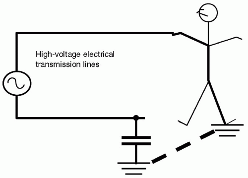 FIGURE 55.3 If neither side of high-voltage transmission lines is grounded, stray capacitances from either line to ground can allow the human to be electrocuted by touching the other line. (Wide lines show complete circuit through human.) For this reason, many (but not all) high-voltage lines have one line grounded. |
At the neighborhood distribution power transformers, power line voltages of approximately 10,000 V are stepped down by pole transformers to 240 or 120 V. However, these 240 or 120 V lines have a possible capacitive connection to the much higher voltage of the upstream transmission line, due to their proximity within the transformer and among the pole wiring. If one of the household service entry wires were not grounded, there would be a possibility of a dangerous capacitive connection to the much higher voltage of the pole transformer primary. If both of the entry wires are left “floating” with respect to ground, a person touching one of them could become part of an unexpected circuit involving the 10,000-plus upstream voltages, by way of the capacitive connections at the pole, as shown in Figure 55.4.
Household and Business Wiring
This explains why one wire of normal household and business power systems is intentionally connected to ground upon entry to the household or business; this limits the possible risk voltage to the delivered voltage (120/240); the capacitive connection to the upstream transmission line voltage is nullified. In the United States, the National Electric Code (NEC) (NFPA 70, published by the National Fire Protection Association) specifies that the grounded wire should be white or gray; it is known as the neutral wire.7 One can generally touch it with no ill effects; its voltage with respect to ground is negligible or “neutral.” The other power-carrying wire is usually black, and is known as the hot wire for obvious reasons. If a human is standing or touching ground, and touches the “hot” wire, they will receive a shock. United States wiring often includes a third wire intentionally connected to the earth that is colored green (or left bare in some household wiring). This wire is not intended under
normal circumstances to carry any current. It has a purely protective function as discussed in the subsequent text.
normal circumstances to carry any current. It has a purely protective function as discussed in the subsequent text.
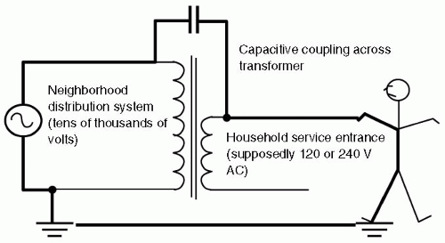 FIGURE 55.4 If neither of the 120/240 V lines going into the household is grounded, they may be dangerously energized by stray capacitive coupling across the pole transformer to the much higher voltage of the neighborhood distribution system, posing a severe electrocution risk. For this reason, one of the wires going into the household is normally grounded, reducing the potential risk voltage to a maximum of 240 V. AC, alternating current. |
Humans are often electrically “connected” to ground. Shoes are not perfect insulators, floors are wet, hands touch water piping that goes into the ground, or other metal structures that either connect to the ground or are intentionally wired to ground. This (gravitational) tendency of humans to maintain connection with the earth, coupled with the grounded nature of typical household or business wiring systems, effectively accomplishes the first of the two connections required to bring about an electric shock. The neutral wire is connected to ground, and humans are often grounded, so they are effectively already connected to the neutral wire. This point is crucial in understanding shock prevention.
Therefore, there is a significant effort to prevent either patients or caregivers from ever contacting the “hot” wire, and thereby making the second required connection to receive a shock. First of all, wires are required to be insulated. Then they are mechanically protected by an outside covering, and strain relief devices are used to avoid excessive strain on entering cabinets or terminating at plugs that would damage the protective insulation. As discussed in the preceding text, the 120-V AC power wiring is a prime electrocution risk. The hospital working environment can mechanically and physically damage the power cord wiring, exposing the dangerous hot wire. Internal to the device, a connection or circuit can become loose or damaged so that the hot wire voltage becomes dangerously loose, potentially touching or becoming conducted to some exposed knob or control. This would set the stage for a possible shock if a person then touched this knob or control.
▪ PREVENTION
Electrocution Protection Techniques
With this understanding, it becomes easy to comprehend the multiple and varied techniques that have been devised over the last century to protect personnel and patients from this hazard. There are four major protection techniques: (i) connection of all exposed surfaces to ground; (ii) double-insulated tools; (iii) isolated power systems, and (iv) ground-fault circuit interrupters (GFCI).
Grounded Exposed Surfaces
The first protection technique is to solidly connect all exposed conductive surfaces (including knobs, controls, and covers) to the household or building ground wire. This forces a nearly zero potential difference between all the metal surfaces that a physician or patient could touch, no matter how many different electric boxes or devices they touched simultaneously. All would be at the same voltage, and hence humans would get no resultant current flow through their body. The longer, third prong of the modern three-wire power plug provides the ground wire to equipment for this purpose, and any attempt to defeat this ground connection negates this protection. Before the development of the modern, three-prong power plugs equipped with ground wire, earlier two-wire power cords were mechanically “polarized” (with one prong taller than the other) to fit into the receptacle only one way, so that the equipment designer would know which power cord wire was “hot” and which was “neutral.” This allowed the designer to preferentially isolate the hot wire inside the device and, in some cases such as kitchen appliances, to connect the “neutral” wire to the outer case. However, a miswired outlet or cord could cause this strategy to backfire, connecting the hot wire right to the metal case of the toaster. Thus was the development of the three-prong plug with separate ground wire.
The explanatory material for Health Care Facilities Standard NFPA 99, also published by the National Fire Protection Association, repeatedly emphasizes that patient protection from electrocution is primarily provided by this grounding system. NFPA 99 emphasizes the goal of maintaining negligible voltage differences between all conductive surfaces that could be touched by a patient under all circumstances. The wording “all circumstances” is crucial. If a live (hot) wire becomes loose inside a monitor and then touches the monitor’s metal case, NFPA 99 stresses that the metal case should still not achieve a dangerous voltage—this requires that the grounding circuit have such low resistance that the large resulting current (termed a fault current) is so easily carried that the resultant voltage on the case remains low until the circuit breaker or fuse trips and removes power from the branch circuit. To achieve this high-quality, lowresistance protective ground path, NFPA 99 requires that new construction electric wiring in patient care areas meet a stringent standard. Ground circuit resistances are tested in at least 10% of receptacles and must be <0.1 Ω for normal grounds (0.2 Ω for special “quiet” grounds). For fixed electric equipment, the potential on exposed surfaces must be measured and must be <20 mV. NFPA 99 calculates that with a fault current of 20 A from a broken device, flowing through a 0.15 Ω ground system for some time until the circuit breaker trips, the equipment case will remain within 3 V of ground—a modest macroshock risk to humans.8
Significant effort is required to achieve this high quality ground: Although the green ground wire is required, measurements have shown that the steel of the building and the metal raceway actually constituted a better conductor. The best grounding is obtained when Chapter 4 of NFPA 99 and Article 250 of NFPA 70 are followed, but in addition, good workmanship goes beyond this. In particular, at each receptacle, there should be a good jumper grounding connection to the metal raceway in addition to the green grounding wire. These connections, as well as raceway connections, should be tight for best protection. Branch circuits to a patient bed cannot come from multiple distribution panels—it must come from only one to minimize the differences in potential between different grounds and neutrals.9
Grounding any and all metal in the environment, regardless of whether it encloses dangerous voltage or is merely a part of a nonelectric piece of furniture, can actually have a detrimental effect by making a ground
more available to a patient. Hence, the latest version of NFPA 70 and 99 do not recommend grounding all “dead” metal. One should avoid grounding the patient if at all possible.
more available to a patient. Hence, the latest version of NFPA 70 and 99 do not recommend grounding all “dead” metal. One should avoid grounding the patient if at all possible.
Leakage Currents Under normal (nonfault) conditions, there should be virtually no current flowing in the protecting ground wiring of an electric device. All power to the device should flow through the “hot” and “neutral” wires. From Ohm’s law, if there is no current flow in the ground wiring, there would be no voltage difference between any points along the ground wiring. This would force all grounded enclosures within an operating room to have identical voltages—all zero. This ensures the safety of the personnel. However, in real life, there is always some leakage connection, whether from imperfect insulation from the equipment to its case or from capacitive coupling from the surfaces of the “hot” wiring itself to the metal surface of the case. As a result, there is a finite but small “leakage” current that flows through the ground wiring of the electric equipment and returns to the power system through this parallel, alternate pathway through the ground wiring instead of through the neutral wire. As long as the ground connection is solidly present and the leakage is small, the voltage of the case of the device will remain negligibly different from zero.
Neutral wires can also erroneously contact the ground wiring. This does not cause any circuit breaker to trip, and may only be recognized by excessive interference with EEG and ECG equipment. It can cause excessive currents to flow in ground wires, causing the potential of “ground” wires to be significantly different from true ground. Ground-fault interrupter systems should be tripped by this sort of fault; however, they are often omitted from patient care areas out of concern for loss of electric service.
Double Insulation
Another electrocution protection strategy was the development of “double-insulated” tools and equipment, qualifying for International Electrotechnical Commission (IEC) class II insulation, carrying an identifying symbol (see Fig. 55.5). Many small electric motorized tools and other appliances used at home and in industry are built with either two substantial layers of insulation or a reinforced single layer of protection equivalent to two layers. They generally have nonmetallic, plastic, nonconducting exteriors. Careful mechanical design keeps all internal wiring mechanically separated from any possible contact with the user. For example, there are no cabinet screws or nuts that can be touched that could also contact any of the wiring. With no exterior metallic surface, there is no real need for a connection to ground, and these tools are marketed with a two-wire polarized plug, containing no ground wire. They are quite acceptable for use within an operating room. However, users in any setting should be aware that there are still dangerous voltages present inside these devices. If they are dropped into water, blood, or saline, and are not completely sealed, the conductive liquid may cross openings to make contact with those dangerous voltages inside, bypassing the insulation and creating a significant hazard for the user. At that point, the utility of the double insulation is lost. Users should not handle such a submerged device while powered. The risk to unwary personnel would be reduced if the power systems were ground-fault protected or isolated, but would be significant if neither of those protective systems are employed.
 FIGURE 55.5 Double insulated symbol applied to double-insulated appliances. |
Of interest, the IEC class III insulation is not a better version of class II and is not acceptable for medical practice. Class III refers to devices that are considered inherently safe because of relatively low voltage power (<60 V DC or 25 V AC), but these voltages are not safe for medical practice, and hence class I or class II protection is required.
Isolated Power Systems
Developed during the time of flammable anesthetics, isolated power systems remove the necessity for one wire of the power system to be grounded by using an isolation transformer. This 1:1 transformer does not change the voltage; it is connected to the conventional grounded 120-V AC power system at its primary input side, and on its isolated secondary output provides 120-V AC through two wires, neither of which is grounded. Although both these output wires are therefore “floating” with respect to ground because the input voltage to the transformer is only 120-V AC (rather than many thousands, as was the case with power line pole transformers), there is little hazard to the users of significant capacitive current flow from the transformer’s input wiring. Because neither power-carrying wire is grounded, the color coding used for conventional branch circuits does not apply; the conductors are simply numbered 1 (orange) and 2 (brown).10
These isolated power systems were advantageous for two reasons. In an era of flammable anesthetics, every effort was taken to prevent any kind of spark from static electricity or electric short circuit. With an isolated power supply, if either power-carrying wire accidentally touched a grounded wire or surface (a situation called a fault), no significant spark would occur; ground simply was not a
part of the power system, so the hot arc that would happen in a conventional power system does not. The system was simply converted back to a grounded system.
part of the power system, so the hot arc that would happen in a conventional power system does not. The system was simply converted back to a grounded system.
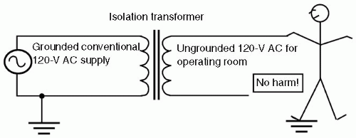 FIGURE 55.6 With an ungrounded, isolated 120-V AC power system in an operating room, no current flows if a human stands on ground and contacts one of either of the two wires of the power system. The grounded person is unharmed because neither wire of the ungrounded power system is connected to ground. AC, alternating current. |
The lack of an arc in this circumstance suggests the second advantage: It is much more difficult to get a macroshock in a room powered with an isolated power system (see Fig. 55.6). That was very important to users who were wearing conductive shoes—well grounded—to reduce the chance of static electricity sparks in an era of flammable anesthetics. Until the first fault (unwanted connection of one power wire to ground) happened, even well grounded personnel and patients in the room were not at risk of macroshock. In modern trauma anesthesia, with wet floors and high volume fluids, this advantage may come to be more appreciated. In an isolated power system, a patient or physician who is already drenched by blood and fluids, by making contact with one wire of the isolated system, would not be electrocuted. They are simply in contact with one wire of a power system, just as the eagle perches unharmed on one power line.
The astute reader then recognizes that the degree of isolation of the power system could be important—perfect isolation from ground would give perfect protection to the unlucky health care worker contacting one wire of such a system. Indeed, when isolated wiring systems are installed, they must meet a stringent standard: The impedance between current-carrying wire and ground must exceed 200,000 Ω, which would guarantee that the system is fairly “isolated.” In such systems, there should be very little current flow in the ground wire. However, capacitance between the electrified wires and nearby ground and imperfect insulation of the real world again come into play, always causing a small, but finite current to flow in the ground wire leads of even isolated power systems. Such a current is termed a leakage current. Initial construction must be such that it is <0.6 mA. As discussed in the preceding text, such a current is of no risk for macroshock. It is quite capable of causing microshock, and hence the separate requirement for isolated patient lead inputs. Engineers have developed methods by which to monitor the “isolation” of an isolated power supply and the leakage current through a line isolation monitor. The line isolation monitor ingeniously measures the maximum possible current that could flow through a person contacting either of the supposedly isolated power wires, and also grounded. Such a current would have to flow out of one of the power supply wires, through the victim to ground, and then flow as a leakage current back to the other power supply wire. Standards require that all isolated power systems have a line isolation monitor visible within the room supplied, and must alarm if the possible hazard from either isolated conductor to ground reaches 5.0 mA, but cannot alarm at <3.7 mA. Stringent requirements in NFPA 99 guarantee that modern line isolation monitors must not interfere with physiologic monitors, a problem with older line isolation monitors.11
Related posts:


Stay updated, free articles. Join our Telegram channel

Full access? Get Clinical Tree


