Ultrasound-Guided Popliteal Sciatic Block
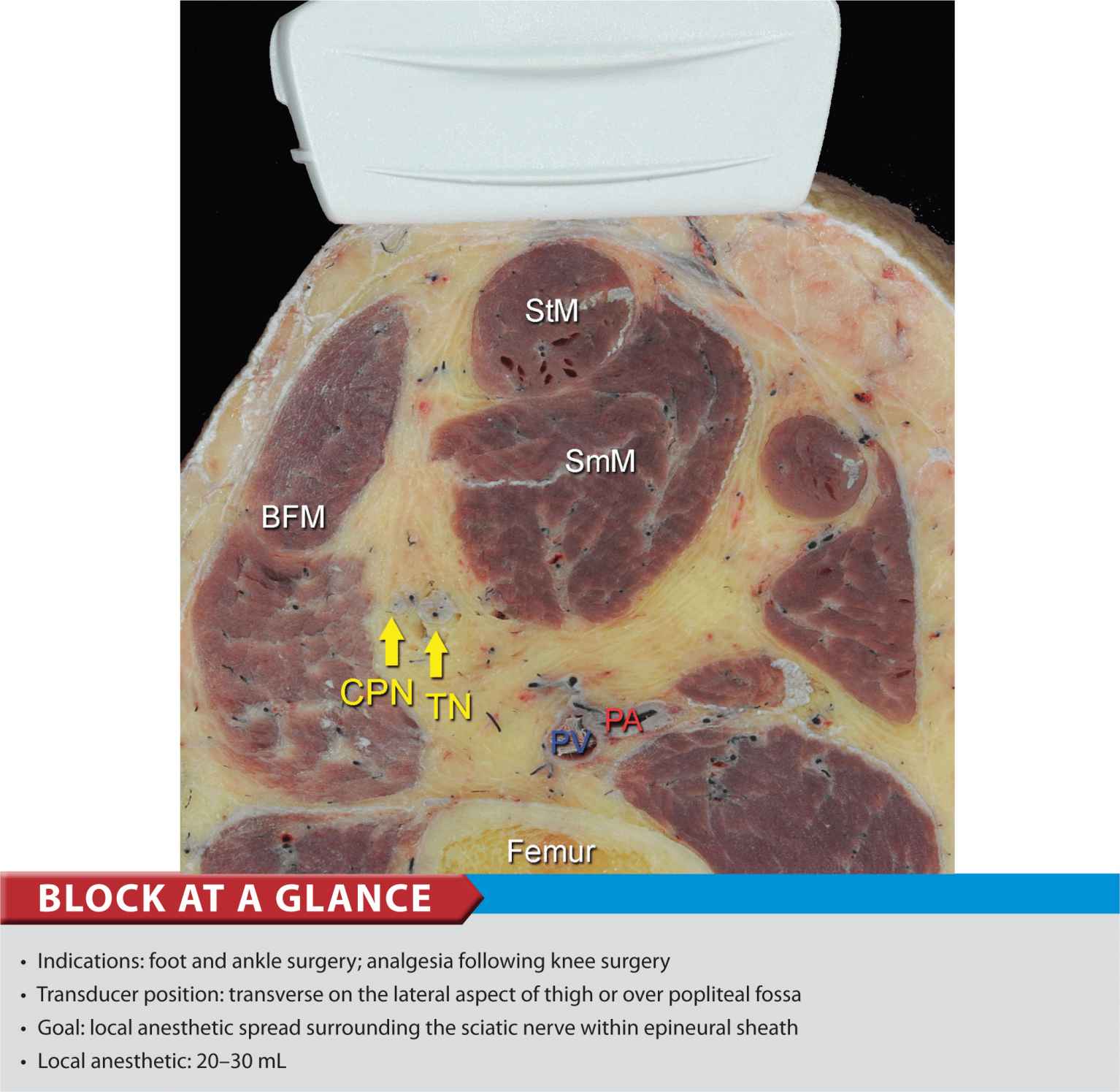
FIGURE 40-1. Cross-sectional anatomy of the sciatic nerve in the popliteal fossa. Shown are common peroneal nerve (CPN), tibial nerve (TN), popliteal artery (PA), popliteal vein (PV), femur, biceps femoris (BFM), semimembranosus (SmM) and semitendinosus (StM) muscles.
General Considerations
Performance of a sciatic block above the popliteal fossa benefits from ultrasound guidance in several ways. The anatomy of the sciatic nerve as it approaches the popliteal fossa can be variable, and the division into the tibial nerve (TN) and common peroneal nerve (CPN) occurs at a variable distance from the crease. Knowledge of the location of the TPN and CPN in relation to each other is beneficial in ensuring the anesthesia of both divisions of the sciatic nerve. Moreover, with nerve stimulator–based techniques, larger volumes (e.g., >40 mL) of local anesthetic often are required to increase the chance of block success and rapid onset. A reduction in local anesthetic volume can be achieved with ultrasound guidance because the injection can be halted once adequate spread is documented. The two approaches to the popliteal sciatic block common in our practice are the lateral approach with patient in supine (more commonly, oblique position) and the posterior approach (Figure 40-2). It should be noted that with the lateral approach, the resulting ultrasound image is identical to the image in the posterior approach. Both are discussed in this chapter. Only the patient position and needle path differ between the two approaches; the rest of the technique details are essentially the same.
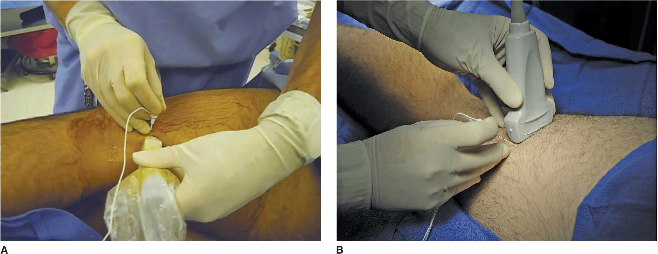
FIGURE 40-2. Posterior approach to ultrasound-guided popliteal sciatic block can be performed with the patient in the oblique position (A) or with the patient prone (B).
Ultrasound Anatomy
With the posterior and the lateral approaches, the transducer position is identical; thus the sonographic anatomy appears the same. However, note that although the image appears the same, there is a 180° difference in patient orientation. Beginning with the transducer in the transverse position at the popliteal crease, the popliteal artery is identified, aided with the color Doppler ultrasound when necessary, at a depth of approximately 3 to 4 cm. The popliteal vein accompanies the artery. On either side of the artery are the biceps femoris muscles (lateral) and the semimembranosus and semitendinosus muscles (medial). Superficial (i.e., toward the skin surface) and lateral to the artery is the tibial nerve, seen as a hyperechoic, oval, or round structure with a stippled or honeycomb pattern on the interior (Figure 40-3A and B). If difficulty in identifying the nerve is encountered, the patient can be asked to dorsiflex and plantar flex the ankle, which makes the nerve rotate or move in relation to its surroundings. Once the tibial nerve is identified, an attempt can be made to visualize the common peroneal nerve, which is located even more superficial and lateral to the tibial nerve. The transducer should be slid proximally until the tibial and peroneal nerves are visualized coming together to form the sciatic nerve before its division. (Figure 40-4A and B). This junction usually occurs at a distance between 5 and 10 cm from the popliteal crease but this may occur very close to the crease or (less commonly) more proximally in the thigh. As the transducer is moved proximally, the popliteal vessels move anteriorly (i.e., deeper) and therefore become less visible. Adjustments in depth, gain, and direction of the ultrasound beam should be made to keep the nerve visible at all times. The sciatic nerve typically is visualized at a depth of 2 to 4 cm.
FIGURE 40-3. (A) The sonoanatomy of the sciatic nerve at the popliteal fossa. The two main divisions of the sciatic nerve, tibial (TN) and common peroneal nerves (CPN), are seen immediately lateral and superficial to the popliteal artery, respectively. (B) Sonoanatomy of the popliteal fossa with the structures labeled. TN and CPN are lateral and superficial to PA. Images 40-3A and B were taken at 5 cm above the popliteal fossa crease where the TN and CPN have just started diverging.
FIGURE 40-4. (A) Sonoanatomy of the sciatic nerve (ScN) before its division. (B) Sonoanatomy of the popliteal fossa with the structures labeled. Shown are ScN, superior and lateral to the popliteal artery (PA), positioned between bicep femoris (BFM) and semimembranosus (SmM) and semitendinosus (StM) muscles.
Distribution of Blockade
Sciatic nerve block results in anesthesia of the entire lower limb below the knee, both motor and sensory, with the exception of a variable strip of skin on the medial leg and foot, which is the territory of the saphenous nerve, a branch of the femoral nerve. The motor fibers to the hamstring muscles are spared; however, sensory fibers to the posterior aspect of the knee are still blocked. For a more comprehensive review of the sciatic nerve distribution, see Chapter 1, Essential Regional Anesthesia Anatomy.
Equipment
The following equipment is needed:
• Ultrasound machine with linear transducer (8–12 MHz), sterile sleeve, and gel (rarely, in a very obese patient, a curved transducer might be needed)
• Standard nerve block tray (described in the equipment section, Chapter 3)
• Two 20-mL syringes containing local anesthetic
• 50- to 100-mm, 21- to 22-gauge short-bevel insulated stimulating needle
• Peripheral nerve stimulator
• Sterile gloves
Lateral Approach
Landmarks and Patient Positioning
This block is performed with the patient in the supine or oblique (more convenient) position. Sufficient space must be made to accommodate the transducer beneath the knee and thigh. This can be accomplished either by resting the foot on an elevated footrest or flexing the knee while an assistant stabilizes the foot and ankle on the bed (Figure 40-5). If nerve stimulation is used at the same time, exposure of the calf and foot are required to observe motor responses.
FIGURE 40-5. Needle insertion technique to block the sciatic nerve in the popliteal fossa using lateral approach with patient in the supine position.
Technique
With the patient in the proper position, the skin is disinfected and the transducer positioned to identify the sciatic nerve (Figure 40-5). If the nerve is not immediately apparent, tilting the transducer proximally or distally can help improve the contrast and bring the nerve “out” of the background (Figure 40-6). Alternatively, sliding the transducer slightly proximally or distally may improve the quality of the image and allow for better visualization. Once identified, a skin wheal is made on the lateral aspect of the thigh 2 to 3 cm above the lateral edge of the transducer. Then the needle is inserted in-plane in a horizontal orientation from the lateral aspect of the thigh and advanced toward the sciatic nerve (Figure 40-7). If nerve stimulation is used (0.5 mA, 0.1 msec), the contact of the needle tip with the sciatic nerve usually is associated with a motor response of the calf or foot. Once the needle tip is witnessed adjacent to the nerve, and after careful aspiration, 1 to 2 mL of local anesthetic is injected to confirm the proper injection site. Such injection should result in distribution of the local anesthetic within the epineural sheath, and often, separation of the TN and CPN. When injection of the local anesthetic does not appear to result in a spread around the sciatic nerve (Figure 40-8), additional needle repositions and injections may be necessary. When injecting into the epineurium, correct injection is recognized as local anesthetic spread proximally and distally to the site of the injection around both divisions of the nerve. This typically results in separation of TN and CPN during and after the injection.
FIGURE 40-6. Sonoanatomy of the popliteal fossa imaged with the transducer positioned as in Figure 40-5. The image appears inverted compared to the image in the lateral/oblique position.
FIGURE 40-7. Simulated needle path and the proper needle tip placement to block the sciatic nerve (ScN) through the lateral approach. BFM – Biceps femoris muscle, SmM – Semimembranosus muscle. StM – Semitendinosus muscle, PA- Popliteal artery.
FIGURE 40-8. Simulated needle path and local anesthetic distribution to block the sciatic nerve in the popliteal fossa using the lateral approach.
Related posts:


Stay updated, free articles. Join our Telegram channel

Full access? Get Clinical Tree


