Regulation of the Circulatory System
An understanding of the relationship and regulation of the circulatory system is fundamental to effective monitoring and interpretation of monitors and the application of hemodynamic monitoring to therapeutic management. The simplified model shown in Figure 10-1 isolates the action of different therapy classes. However, this simplified physiologic model is complicated by the autonomic nervous system as it regulates stroke volume, heart rate, and SVR from feedback, predominantly from the baroreceptors, to maintain the blood pressure in a narrow range. Current concepts of circulation are based on the Guyton’s time averaged model of MAP = CO × SVR as represented by the following series of equations:9
MAP=CO×SVRCO=SV×HRCO=SV×HR×SVR
The application of a therapy that alters either stroke volume or SVR will result in a compensatory change in the other variable, as the autonomic nervous system acts to preserve blood pressure by regulation of the other two variables. Consequently, the autonomic nervous system masks changes in stroke volume or SVR by compensatory regulation of the counter variable to preserve the blood pressure. Measurements of both stroke volume and SVR are required to adequately identify circulatory abnormalities and guide interventions. This also ensures that measures of blood pressure alone are less sensitive to changes in hemodynamics, than measures of stroke volume and SVR.
The adoption of Doppler technologies, which measure real time stroke volume, provides instantaneous measurements of ventricular–arterial coupling such as arterial elastance (Ea) or dP/dV, and allows Guyton’s law to be written as BP = SV × Ea.
Doppler Background
Doppler Method
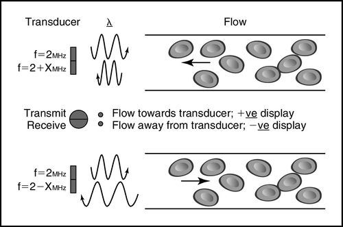
The Doppler method depends on a transducer transmitting ultrasound waves into the body at a known fixed frequency, which are then reflected by the tissues and cells, predominantly red blood cells, and the reflected ultrasound waves are measured by the Doppler system (Figure 10-2 and Box 10-1).
Doppler Equation
The Doppler equation allows for calculation of the blood velocity from measurement of the reflected Doppler signals. The frequency of the reflected waves is subtracted from that of the transmitted waves to calculate the frequency shift (df), and then the blood velocity (v), can be calculated according to the Doppler equation as shown in Box 10-1.10
Doppler Signal
The velocity of the reflectors, in this case red blood cells, can be plotted on a time–velocity display to generate a Doppler flow profile in which flow toward and away from the transducer is represented (Figure 10-3). The characteristic Doppler flow waveforms display the following:
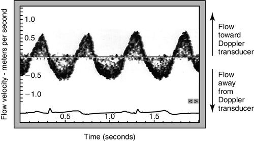
The intensity of the signal is also plotted and reflects the density of reflectors, in this case red blood cells. The greater the number of cells travelling at any velocity, the more dense the signal appears.
Doppler Flow Profile
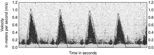
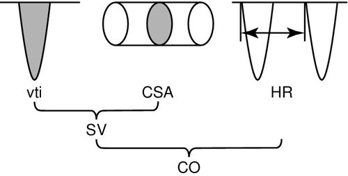
The Doppler flow profile can be traced to derive an area under the curve, also known as a velocity time integral (vti), according to the standard echocardiographic method (Figure 10-4). The velocity time integral is the stroke distance (SD) or distance that a single red blood cell travels per stroke in centimeters and varies from about 25 cm when measured at the aortic valve, to 10 cm when measured in the descending thoracic aorta. To calculate flow volume the velocity time integral (vti) in centimeters (cm), is multiplied by the flow in a cross-sectional area in square centimeters to obtain a measurement of stroke volume in cubic centimeters,11 as shown in Figure 10-5. The strength of the Doppler method is that it measures flow directly across the ventricular–arterial valves or within the aorta and measures each of the component variables directly from the Doppler flow profile, velocity time integral (vti) and heart rate with high precision. Therefore, calculations derived from these measurements are highly accurate as seen in Box 10-2.
Doppler Flow Volume Calculations
The accurate calculation of flow volume using the Doppler method requires that the cross-sectional area be measured at the point where the Doppler signal is acquired. For noninvasive transcutaneous ultrasound this is at the level of the aortic valve or pulmonic annulus, and for minimally invasive esophageal probes, the cross-sectional area is measured at the level of the descending thoracic aorta. Both methods use predictive algorithms for the calculation of the cross-sectional area. Despite differences between the device algorithms, comparative studies have demonstrated good agreement between the two methods.12–14
Therefore, despite different Doppler monitoring sites and different approaches to predicting flow cross-sectional area, both transcutaneous and esophageal Doppler methods can be used interchangeably, with the choice of preferred device based on the clinical application, patient needs, and operator comfort. This interchangeability of results suggests a robustness of the Doppler method.
Angle of Insonation
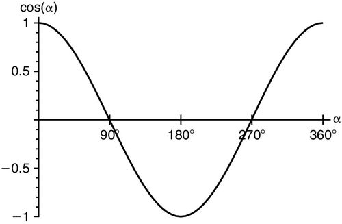
To accurately calculate flow velocity with Doppler ultrasound, the operator must align the beam along the flow toward or away from the transducer, at 0 or 180 degrees, so that the cos Ø component of the Doppler equation equates to “1” (Figure 10-6). Any nonparallel angulation will result in cos Ø being less than 1 and result in underestimation of the blood flow velocity. If the beam is directly perpendicular to flow, at 90 degrees, or 270 degrees, no Doppler shift will occur and no velocity can be detected. In clinical practice, Doppler beam angulation is not a limitation as any under-measurement is usually small; in serial measures from the same point of insonation, the error is exactly repeated, so the monitoring function is unaffected. The Doppler equation predicts an error in stroke volume velocity of less than 6% with an insonation angle of ± 20 degrees. Thus, insonation within a 40-degree sector results in Doppler measurements of more than 94% reliability. Regardless, even if the insonation angle is greater than 20 degrees, if the angle remains unchanged between repeated measurements, the sensitivity to hemodynamic change remains 5% to 10% and is much more sensitive than other clinical monitoring methods.15
Doppler Parameters
By combining the Doppler velocity flow profile tracing (vti), the calculated velocity, and a proprietary algorithm, a number of hemodynamic parameters can be calculated. Further input of common physiologic variables of blood pressure, pulse arterial oxygen saturation, pulse oximetry (SpO2), and central venous oxygen saturation (ScvO2), allows calculation of additional physiologic variables. These variables can all be indexed to body surface area for comparison across sizes and ages.16 Although all values can be determined for each single beat, they can also be averaged over a number of beats to provide a more representative reference measure. As most hemodynamic parameters are mathematically derived from stroke volume measurement, the clinical accuracy and effectiveness of these hemodynamic variables is dependent on the accuracy with which Doppler measures stroke volume, and Doppler has a proven capacity to accurately measure stroke volume and small changes in it.
Doppler Transducers
Doppler ultrasound transducers are constructed from piezoelectric materials that convert pressure to electricity (functioning as transmitters) and electricity to pressure (functioning as receivers). With the application of an alternating current, the transducer element expands and contracts at a high frequency related to the frequency of the current and the thickness of the piezoelectric crystal. In clinical practice this characteristic frequency is usually in the range of 2 to 10 megahertz (MHz). This high-frequency contraction and expansions transmits compression and rarefaction waves into any coupled tissue. Normal tissue, which is substantially composed of water, transmits these waves at approximately 1540 meters per second. With transcutaneous Doppler, a hydrophilic-soluble gel applied between the skin surface and the transducer augments acoustic coupling. This transmitted ultrasound wave passes through the body until it meets a reflector or acoustic interface (i.e., a solid organ), and is returned to the transducer, where the signal is reconstructed to form an ultrasound image. Air and bone are high-level reflectors of ultrasound waves and so return the majority of the ultrasound beam, casting acoustic shadows and preventing transmission and deeper tissue insonation. Broadly, four different ultrasound modalities exist: M-mode, two-dimensional (2D), three-dimensional (3D), and Doppler (Table 10-2), but only Doppler has been applied to hemodynamic monitoring.17
Table 10-2
Comparison of Doppler Hemodynamic Monitoring Technologies
| Transcutaneous (USCOM) | Esophageal (CardioQ-EDM) | |
| Access | Transcutaneous | Transesophageal |
| Doppler modality | Continuous wave | Continuous wave |
| Measurement site | Aortic valve and pulmonary valve flow | Descending thoracic aortic flow |
| Algorithm | Anthropometry—height-based in adults and children, weight-based in neonates | Pulmonary artery catheter (PAC) database |
| Invasiveness | Noninvasive | Minimally invasive |
| Morphology | No | No |
| Monitoring | Yes | Yes |
| Auto-trace | Yes | Yes |
| Stroke volume sensitivity to detect a change in cardiac output | 5% | 4% |
| Advanced parameters and trending | Yes | Yes |
| Examination time | 1 to 5 minutes | Less than 5 minutes after anesthesia induction or sedation administration |
| Validation | 26 weeks to 110 years | 0 to 99 years |
| Application | All | Peri-operative optimization |
| Training time | 3 days | 12 examinations |
| Complications | None | Risks associated with esophageal probe placement are similar to orogastric or nasogastric tube placement |
Spectral Doppler Ultrasound
Doppler ultrasound can be further divided into spectral Doppler ultrasound, in which the velocity change is displayed across a time–velocity spectrum, and color Doppler, in which frequency shift is mapped as color-coded information on a 2D/3D B-mode image. High-velocity filters can be applied to measure high-velocity flow, usually blood flow, between 0.2 and 6 meter per second (m/s), and low-velocity flow, usually tissue motion, with a velocity that is usually less than 0.1 m/s. Both transcutaneous ultrasound and esophageal ultrasound utilize spectral Doppler imaging of moving blood.
The two different types of spectral Doppler ultrasound, continuous wave and pulse wave Doppler, have different properties, modes of generation, applications, and limitations. Pulse wave Doppler involves setting a sample volume in the insonation field to measure velocities at a fixed location in the body and pulsing ultrasound into the body in small wave clusters, usually in the order of two to three wavelengths. Continuous-wave Doppler involves uninterrupted streaming of the Doppler beam directed at the target, usually across the aortic valve or pulmonic valve. Both continuous-wave and pulse-wave Doppler have been demonstrated to be 96% to 98% accurate across the range of clinical velocities from − 4 m/s to 4 m/s in phantoms.18 The reproducibility of continuous wave Doppler approaches 98%. However, for pulse wave, where the location of the sample volume creates additional variability, the reproducibility is approximately 77%.19,20 Therefore, continuous wave is the preferred method for measurement of transvalvular flow.20 Both transcutaneous and esophageal Doppler monitoring devices use continuous wave Doppler.
Clinical Applications of Doppler Monitoring
Quantitating the hemodynamic response to fluids, inotropes, and vasoactive medications is crucial for patient management. Understanding of a number of key Doppler parameters and concepts is important when utilizing Doppler for clinical assessment. Because stroke volume is directly modulated by preload, contractility, and afterload, monitoring stroke volume provides simple quantitation of the effectiveness of circulatory therapeutic interventions.
Preload and Stroke Volume
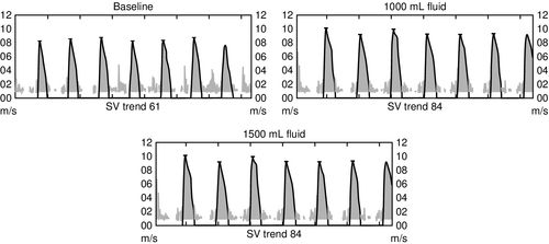
Preload is the volume in the ventricle at end diastole, and it is this volume that increases ventricular myocyte stretch prior to contraction. Increasing the intravascular fluid volume and thus increasing preload volume results in increased stroke volume. Fluid responsiveness, defined as an increase in stroke volume associated with volume expansion, offers a very direct method for assessment of preload responsiveness and is demonstrated in Figure 10-7. Preload can either be increased with an intravenous (IV) fluid infusion or decreased with a diuretic.

Stay updated, free articles. Join our Telegram channel

Full access? Get Clinical Tree


