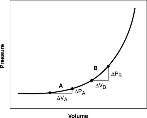
Small volume increases in one or two of the intracranial contents can be tolerated with a reciprocal decrease in the other one or two volumes. This compensation for small increases in volume between the three components—blood (arterial and venous), CSF, and brain tissue—is known as the Monro-Kellie Doctrine.5,6 In pathological states, as the intracranial volume increases, the brain has limited compensatory mechanisms, including (1) shunting of the CSF out of the ventricular system and into the lumbar subarachnoid space and perioptic subarachnoid space, and (2) return of venous blood out of the brain through the internal jugular veins and back to the heart. Once these compensatory mechanisms are exhausted, ICP begins to increase (Figure 21-2). With an increasing ICP, pressure gradients are generated which will result in herniation of brain tissue, if effective emergency interventions are not undertaken.
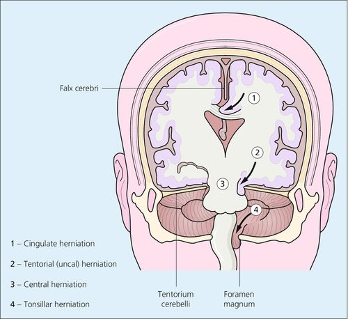
Although an ICP greater than 20 mm Hg is generally considered elevated requiring treatment, patients herniate at various values for reasons that are not completely understood. Herniation may be subfalcine (cingulate), transtentorial (central and uncal), tonsillar (at the foramen magnum), or extracranial (through a traumatic or surgical defect) (Figure 21-3).
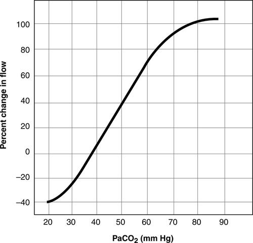
Normal ICP is 5 to 15 mm Hg5,6 (Table 21-1). Although a systolic and diastolic component to the ICP waveform is evident, ICP is read as a mean value (Figure 21-4). The ICP waveform consists of three components—cardiac, respiratory, and vasogenic—as determined by spectral analysis.7 ICP is influenced by a number of cerebral regulatory mechanisms, including the partial pressure of arterial carbon dioxide (PaCO2), cerebral blood flow (CBF), cerebral metabolism coupling, and pressure autoregulation. The PaCO2 is a potent vasodilator. As a result, as the PaCO2 increases, CBF increases, resulting in increased CBF and CBV (Figure 21-5). In contrast, lowering of the PaCO2, such as through hyperventilation, decreases CBV and CBF and may result in ischemia.8
Table 21-1
Normal Values
| Parameter | Normal Values | Comments |
| ICP | 5-15 mm Hg | Intraventricular catheter represented the gold standard for obtaining the ICP waveform and mean value. |
| CPP | 60-160 mm Hg | CPP = MAP – ICP |
| CBF (global) | 50-100 mL/100 g/min (global brain CBF) 80 mL/100 g/min (gray matter) 20 mL/100 g/min (white matter) | Calculated as: CBF = CPP ÷ cerebrovascular resistance |
| CMRO2 | 3.2 mL/100 g/min (global brain CMRO2) 6 mL/100 g/min (gray matter) 2 mL/100 g /min (white matter) | |
| PbtO2 | 25-30 mm Hg | A specialized fiberoptic tipped catheter placed into brain tissue is required to measure brain tissue oxygen levels. |
| SjvO2 | 55%-70% | A specialized fiberoptic catheter inserted into the jugular vein |
| AjvDO2 | 4-8 mL/dL | Calculated value |
AjvDO2, Arteriojugular venous oxygen difference; CBF, cerebral blood flow; CMRO2, cerebral metabolic rate of oxygen; CPP, cerebral perfusion pressure; g/min, grams per minute; ICP, intracranial pressure; MAP, mean arterial pressure; mL, milliliters; mL/dL, milliliters per deciliter; PbtO2, brain tissue oxygenation; SjvO2, jugular venous oxygen saturation.
Normally, a decrease in cerebral metabolic rate (CMR) results in a decrease in CBF; however, this mechanism may not be intact in neurologically injured or ill patients.5,9 Systemic blood pressure and ICP also have a dynamic interplay. In the presence of intact cerebral autoregulation (discussed later), increased blood pressure may accompany increased ICP spontaneously or be induced pharmacologically. This will result in a compensatory decrease in the diameter of cerebral blood vessels, lower CBV, and consequently decreased ICP.3
Cerebral Perfusion Pressure
Cerebral perfusion pressure (CPP) has been defined as the pressure that drives CBF into the brain’s microcirculation.10 Clinically, it is calculated as mean arterial pressure (MAP) minus ICP. Adequate CPP provides some protection against secondary ischemia. However, to date, adequate CPP for each patient is not known. Evidence-based guidelines such as the Brain Trauma Foundation’s Guidelines for the Management of Severe Traumatic Brain Injury support a CPP range of 50 to 70 mm Hg for adults.11 However, the CPP threshold may vary from patient to patient, depending on such factors as autoregulatory status and intracranial compliance.10 Intracranial compliance is defined as a change in ICP in relationship to the change in intracranial volume.5,6 Elevated CPP in neurological injury or illness does not necessarily result in improved outcomes.12,13
Cerebral Blood Flow
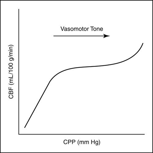
The brain normally receives 15% to 20% of the cardiac output in the healthy adult.14–16 CBF has been defined as CPP divided by cerebrovascular resistance. In the uninjured brain, increases in CPP and cerebrovascular resistance (vasomotor tone) result in controlled increases or decreases in CBF, as needed, to protect the brain against cerebral ischemia and hyperemia (Figure 21-6). The average global normal CBF is 50 to 100 mL/100 g/min.14–16 Flow varies in white and gray matter, with gray matter (the cell bodies of the neurons) being more metabolically active and having greater energy (oxygen and glucose) requirements. The average CBF to white matter is 20 mL/100 g/min, whereas the average CBF to gray matter is 80 mL/100 g/min.14–16
CBF is regulated by a number of factors, including metabolism, PaCO2, partial pressure of arterial oxygen (PaO2), blood viscosity, and cerebral autoregulation. The relationship with the PaCO2 is linear; as the PaCO2 increases from 20 to 80 mm Hg, CBF increases. In contrast, as the PaCO2 decreases, CBF decreases. CBF is unaffected by PaO2 when the PaO2 is greater than 50 mm Hg. However, when the PaO2 is less than 50 mm Hg, as the PaO2 decreases, CBF increases.6 CBF is inversely related to blood viscosity. As viscosity increases, CBF diminishes. Viscosity is primarily influenced by hematocrit. Hemodilution enhances CBF by improving the rheology (flow).16 The role of cerebral metabolism and cerebral autoregulation in CBF is described below.
Cerebral Metabolism
CBF and cerebral metabolism are normally tightly coupled. A change in cerebral metabolism and the cerebral metabolic rate of oxygen (CMRO2) normally results in a corresponding change in CBF. If the metabolic needs are heightened, CBF increases. If the metabolic demands are lessened, CBF decreases both globally and regionally in the brain. The average CMRO2 globally in the brain is about 3.2 mL/100 g/min.16 Similar to CBF, CMRO2 also varies in white and gray matter, with white matter CMRO2 averaging 2 mL/100 g/min and gray matter averaging 6 mL/100 g/min.16 The primary source of energy for the brain is glucose. Oxygen is required for aerobic metabolism.
Cerebral Autoregulation
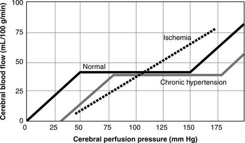
Cerebral autoregulation is the ability of the cerebral blood vessels to constrict and dilate as needed to maintain adequate cerebral perfusion. In the normal adult, cerebral autoregulation is considered operational over a range of MAP between 60 and 160 mm Hg or CPP between 50 mm Hg and 150 mm Hg (accounting for a normal ICP of 10 mm Hg)15–17 (Figure 21-7). Cerebral autoregulation protects the brain from injury related to ischemia or hyperemia. If autoregulation is impaired regionally or globally or MAP or CPP is outside these limits, the brain is dependent on the systemic blood pressure and may be at risk for secondary injury. Cerebral autoregulation is impacted by metabolic, myogenic, and neurogenic mechanisms.15 Possible chemical mediators include adenosine, nitric oxide, protein kinase C, melatonin, prostacyclin, and activated potassium channels.16 The term myogenic mechanism refers to the response of vascular smooth muscle to changes in perfusion or transmural pressure. The neurogenic response of the cerebral blood vessels may involve such neurotransmitters as norepinephrine, neuropeptide Y, cholecystokinin, acetylcholine, and peptides. The blood pressure range for intact cerebral autoregulation may be different for patients who are chronically hypertensive. They may require a higher range of MAP or CPP to maintain CBF, and their autoregulatory curve is said to be “shifted to the right.”16,17 Following catastrophic brain injury or illness, autoregulation may be impaired or abolished regionally or globally.
Cerebral Ischemia
Cerebral ischemia has been defined as a CBF of 18 to 20 mL/100 g/min.14 Ischemia may lead to cerebral infarction. Neuronal death has been found to occur at a CBF of 8 to 10 mL/100 g/min.14 Inadequate CBF may be global or regional and relative or absolute. Whenever the CBF does not meet the cerebral metabolic demands, the brain is at risk. At a cellular level, an ischemic cascade has been hypothesized; in this cascade, increased levels of toxic excitatory neurotransmitters are released; calcium moves intracellularly; and free radicals injure the neuronal cell membrane in a process known as lipid peroxidation.10 Although much of the damage may occur with primary brain injury or insult, secondary brain injury such as hypotension, hypoxia, fever, hypoglycemia, hyperglycemia, hypernatremia, hyponatremia, hypercapnia, hypocapnea, hyperemia, increased ICP, and decreased ICP may compound the damage.5
Cerebral Hyperemia
Cerebral hyperemia, an absolute or relative excess of blood flow, occurs when CBF exceeds the brain’s metabolic demand. Excess CBF results in increased cerebral blood volume and may contribute to increased ICP and decreased CPP. Cerebral hyperemia sometimes follows TBI in children or young adults and may contribute to secondary injury. Cerebral hyperemia is thought to represent an impairment of cerebral autoregulation. As with other derangements of cerebrovascular physiology, hyperemia may be absolute or relative, associated with a regional or global decrease in metabolic demand.14,15
Cerebral Vasospasm
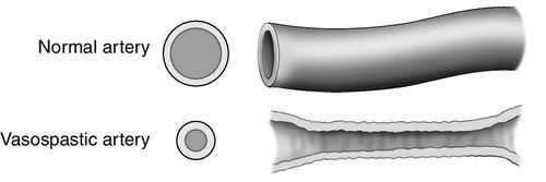
Cerebral vasospasm is a sustained narrowing of cerebral arteries (Figure 21-8). It is thought to be the result of vasoconstriction, edema of the vascular endothelium, remodeling of the tunica media (the muscular layer of the vessel), subendothelial fibrosis, or a combination of all these factors.18 As a result of the narrowing, the total blood volume flowing through the vessel is compromised, resulting in decreased CBF and a fall in oxygen and glucose delivery, which leads to cerebral ischemia and infarction. The inadequate blood supply associated with cerebral vasospasm has been termed delayed cerebral ischemia (DCI).19
Vasospasm may be radiographically visualized on angiography or quantified indirectly by the measurement of flow velocities by transcranial Doppler (TCD). A patient who has vasospasm may or may not present clinically with neurologic deficits. Also, a patient with clinical deterioration that is thought to be related to vasospasm may not show radiographic evidence. Cerebral vasospasm is most frequently associated with aSAH but is also associated with traumatic SAH. Following aSAH, cerebral vasospasm occurs after day 3 but ends before day 21. It most commonly occurs between days 4 and 14, with a peak incidence on day 7.18 Vasospasm may involve multiple vessels both proximal and distal to the ruptured aneurysm. Vasospasm with delayed cerebral ischemia (DCI) is associated with cerebral infarction and increased morbidity and mortality.20–22 Cerebral vasospasm after subarachnoid hemorrhage is a major cause of secondary neuronal injury.
Neurogenic Pulmonary Edema
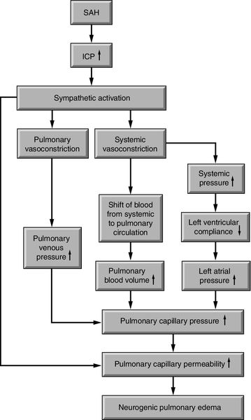
Following severe brain injury or illness, some critically ill neuroscience patients are at risk for neurogenic pulmonary edema, which may be abbreviated as NPE. Onset is rapid and may further compromise the critically ill neuroscience patient. Hypoxia from the sudden increase in interstitial and alveolar pulmonary fluid contributes to secondary brain injury.23,24 Neurogenic pulmonary edema is most often associated with aSAH and severe TBI and has also been reported with status epilepticus and cerebellar hemorrhage.23,24 The pathophysiology is not clear. At least three different etiologies are thought to be responsible for the development of neurogenic pulmonary edema: (1) a dramatic increase in ICP and corresponding decrease in cerebral perfusion globally; (2) cerebral hemorrhage; or (3) focal ischemia in specific areas of the brain, including the vasomotor centers located in the dorsal medulla of the brainstem such as the area postrema, and the solitarius tractus nuclei or the posterior hypothalamus. These areas provide input and output to the pulmonary system.23,25 As a result of increased ICP or cerebral ischemia, one of two mechanisms may occur: (1) the cerebral injury results in a sympathetic response followed by an increase in pulmonary hydrostatic pressure, which leads to an increase in pulmonary capillary permeability, or (2) the cerebral injury results in an inflammatory response such as the release of cytokines and chemokines, which leads to an increase in pulmonary capillary permeability23 (Figure 21-9).
The clinical presentation of neurogenic pulmonary edema varies. It typically occurs at the time of the initial brain injury; however, it may also present with neurologic deterioration. In its purest form, it presents as pulmonary edema in the absence of left ventricular failure. Increased heart and respiratory rates, pulmonary crackles in the bases, respiratory failure, and the absence of a cardiac gallop are more frequently reported. Unilateral neurogenic pulmonary edema has been reported as well.23
The diagnostic workup for neurogenic pulmonary edema includes chest radiography, echocardiography, electrocardiography (ECG), and central venous pressure (CVP). The chest radiography reveals bilateral pulmonary infiltrates. Echocardiography, ECG, and CVP are typically normal. If a pulmonary artery catheter is in place, it may reveal a transient increase in pulmonary artery occlusion pressure (PAOP). Neurogenic pulmonary edema must be differentiated from aspiration pneumonia, ventilator-associated pneumonia (VAP), ventilator-induced lung injury, and acute respiratory distress syndrome (ARDS).23
The management of neurogenic pulmonary edema includes treatment of the catastrophic brain injury with normalization of the ICP and CPP, mechanical ventilation, and diuretic therapy with maintenance of adequate CPP. If needed for blood pressure support, norepinephrine (Levophed) and epinephrine have not been found to worsen neurogenic pulmonary edema as these medications increase pulmonary capillary pressure but not pulmonary vascular permeability. Although neurogenic pulmonary edema is of non-cardiac origin, dobutamine (Dobutrex) has been reported to provide beneficial effects such as improvement in the cardiac index (CI), left ventricular stroke work index (LVSWI), pulmonary artery pressure (PAP), and P/F ratio, without a decrease in cerebral oxygenation.23 The P/F ratio is calculated as PaO2 divided by the FiO2 (fraction of inspired oxygen). However, caution is advised, as dobutamine may lower blood pressure, and attention to maintenance of adequate CPP is imperative.26 Beta-blockers are not recommended.23
Neurogenic Stunned Myocardium
Severe brain injury or illness has also been associated with neurogenic stunned myocardium, also referred to as neurogenic stress cardiomyopathy. Neurogenic stunned myocardium has most often been associated with aSAH but has also been reported in association with increased ICP, stroke, seizures, and meningitis.27 As with neurogenic pulmonary edema, the pathophysiology is not clear. The general areas of the brain responsible for the clinical presentation may be similar to neurogenic pulmonary edema, including the brainstem and diencephalon, incorporating the thalamus and hypothalamus, and also the insular cortex between the temporal and frontal lobes. The specific area in the medulla oblongata that is thought to be responsible for neurogenic stunned myocardium includes the nucleus tractus solitarius (Figure 21-10). One postulated mode of transmission includes a sympathetic mediated response at the insula and hypothalamus with connections through the medulla oblongata of the brainstem and lateral horn of the spinal cord where the sympathetic nervous system sends input to the heart via the thoracic nerve roots and the cervical ganglia27 (Figure 21-10).
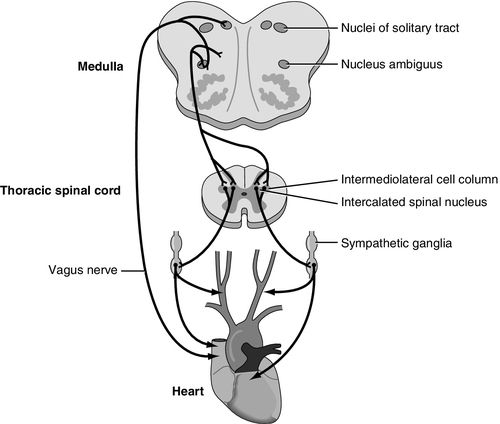
At least three mechanisms have been proposed in neurogenic stunned myocardium. They are (1) ischemia induced coronary artery spasm; (2) cardiac microvascular dysfunction; and (3) the sympathetic-mediated hypothesis. Neither the first nor the second mechanism has been supported by substantial evidence. The release of catecholamine into the bloodstream as a result of the catastrophic brain injury is associated with increased cardiac enzymes creatine kinase–MB (CK-MB) and troponin T (cTnT). In addition the local release of norepinephrine directly into the heart from sympathetic nervous system nerve terminals may contribute to resultant necrosis of the myocardial contraction bands as well (Figure 21-10).27
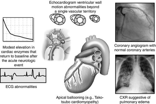
Clinical manifestations of neurogenic stunned myocardium including regional wall motion abnormalities (RWMA), abnormalities on echocardiography, pulmonary edema on chest radiography, cardiac biomarker elevation, and ECG changes but with normal coronary arteries.28 Cardiac arrhythmias may cause hemodynamic instability, resulting in sudden death. In addition to arrhythmias, ECG abnormalities may include QT prolongation, ST segment changes, new Q waves, U waves, and ECG criteria diagnostic for left ventricular (LV) hypertrophy. With regard to cardiac biomarkers, CK-MB may increase more slowly and peak lower than is seen in myocardial infarction.28 Troponin I (cTnI) may be a more sensitive indicator for LV dysfunction. In neurogenic stunned myocardium, LV dysfunction is sometimes reversible. The degree of permanent cardiac injury, especially myocardial necrosis, is related to the severity of the neurologic injury. Elevated brain natriuretic peptide may also rise as an indicator of the dysfunction of the myocardium. On echocardiography, regional wall abnormalities may manifest differently with neurogenic stunned myocardium compared with myocardial changes related to coronary artery disease.27 Neurogenic stunned myocardium may progress to low ejection fraction with acute heart failure sometimes manifesting as Tako-tsubo cardiomyopathy, with left apical ballooning27 (Figure 21-11).
As with neurogenic pulmonary edema, management of neurogenic stunned myocardium includes appropriate management of the underlying neurologic injury. If the neurogenic stunned myocardium progresses to wall abnormalities and ventricular failure, this may prove difficult, as management of the neurologic illness or injury and that of the neurogenic stunned myocardium may be in direct conflict. Use of a pulmonary artery catheter to guide management of fluids and vasoactive agents may be necessary, and in rare instances, intra-aortic balloon counterpulsation may be required to support the patient’s systemic and cerebral hemodynamics.27
Central Nervous System Measurement Methods
Overview
A number of measurement methods are available for monitoring the brain in catastrophic brain injury or insult. Although nothing can be done to reverse primary neuronal injury, the goal is prevention or minimization of secondary neuronal injury. Secondary insults include hypoxia, hypercapnia, hypotension, hypertension, hyperglycemia, hypoglycemia, hypernatremia, hyponatremia, fever, increased ICP, decreased CPP, and cerebral vasospasm. No amount of intracranial dynamic monitoring negates the need for the bedside assessment; however, monitoring the brain can provide additional data to assist in clinical decision-making. This section discusses various methods of ICP and CPP monitoring, including the external ventricular catheter drain (EVD), transducer-tipped catheters, both fiberoptic and electronic strain gauge, and air pouch technology. Methods of brain oxygen monitoring to be included are brain tissue oxygenation (PbtO2), the fiberoptic retrograde jugular bulb catheter (jugular venous oxygen saturation [SjvO2]), and near-infrared spectroscopy (NIRS). Application of transcranial Doppler (TCD), as an indirect measurement of CBF will be discussed. Although less commonly used to quantify CBF, thermal diffusion flowmetry (TDF) and laser Doppler flowmetry (LDF) will also be reviewed.
Cerebral microdialysis is another tool that will be briefly discussed. Additional adjuncts are temperature measurement, partial pressure of end-tidal carbon dioxide (PetCO2) monitoring, and pupillometry. Each measurement method will be discussed with regard to clinical procedure, technical considerations, indications setup, establishing a baseline assessment, maintenance, troubleshooting, and patient safety, comfort, and education.
Intracranial Pressure Monitoring and Cerebral Perfusion Pressure Monitoring
External Ventricular Drain
The external ventricular catheter, or ventricular drain with an external strain gauge transducer is considered the gold standard for ICP monitoring.2,29 Compared with other ICP monitoring systems, it is said to be the least expensive, most accurate, and most reliable.29 A catheter is inserted into the anterior horn of one of the two lateral ventricles of the brain, preferably on the nondominant side.2,29 The ventricular catheter is attached to an fluid-filled external strain gauge transducer and drainage system. The external ventricular catheter has the added advantage of allowing CSF drainage as a method of controlling ICP in addition to ICP monitoring. The ventriculostomy catheter is radiopaque and is magnetic resonance imaging (MRI) compatible.
Clinical Procedure
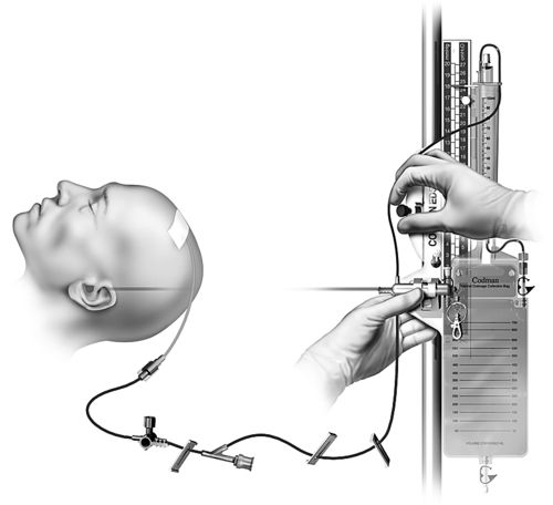
The external ventricular catheter may be inserted in the operating room or at the bedside in the critical care unit. Sterile technique must be maintained regardless of the location. The critical care unit environment must be held to the standard of an operating room with use of sterile gowns and gloves, hair covers, face masks, and sterile draping; minimal movement in and out of the room; and a closed door. Approximately 30 minutes to an hour before beginning the procedure, an antibiotic may be ordered for prophylaxis. Prior to draping, the patient’s hair may be clipped, and the skin prepared. The use of chlorhexidine is controversial because of possible neurotoxicity associated with chlorhexidine.30 Povidone iodine is preferred. The physician will make the skin incision and burr hole, open the dura, and insert the catheter toward the opposite nare. Once CSF is obtained, the primed external ventricular drainage system will be connected to the catheter (Figure 21-12). The catheter is tunneled to exit a few centimeters away from the burr hole and the incisions are closed. If cerebral edema with midline shift or collapse of the lateral ventricle is present, insertion of the catheter may be more complicated.
Indications
Indications for ICP monitoring in general include TBI, ICH, SAH, hydrocephalus, hepatic failure with encephalopathy, acute ischemic stroke with large infarction, and meningitis.2–6 The Brain Trauma Foundation’s Guidelines for the Management of Severe Traumatic Brain Injury recommend ICP monitoring for the following reasons:
(1) post-resuscitation Glasgow Coma Scale (GCS) of 8 or less, with an abnormal computed tomography (CT) (Level II of III recommendation); or (2) a post-resuscitation GCS of 8 or less with a normal CT with at least two of the following: hypotension defined as a systolic blood pressure less than 90 mm Hg, age over 40 years, and decorticate or decerebrate posturing (Level III of III recommendation, the lowest quality of evidence) 31,32 (Table 21-2).
Table 21-2
Brain Trauma Foundation Evidence-Based Guidelines for Severe Traumatic Brain Injury (TBI)
The patient who has a GCS of 9 or greater may also be considered for ICP monitoring, particularly if the patient is unable to participate in the bedside assessment for any reason33 (Table 21-3). The American Heart Association and American Stroke Association (AHA/ASA) have recommended ventriculostomy and insertion of an external ventricular drain after acute aneurysmal SAH with decreased level of consciousness, which is a Class I out of III (highest quality of evidence) recommendation related to the communicating hydrocephalus associated with aSAH34–36 (Table 21-4).
Table 21-3
The Glasgow Coma Scale (GCS)
From Rengacharry SS, Ellenbogen RG: Principles of neurosurgery, ed 2, Philadelphia, 2005, Elsevier.
Table 21-4
AHA/ASA Guidelines for Hemodynamic and Intracranial Parameters in Spontaneous Aneurysmal Subarachnoid Hemorrhage (aSAH)
The AHA/ASA recommendation also includes ICP monitoring and maintenance of a CPP of 50 to 70 mm Hg for spontaneous ICH (patients with a GCS of < 8 with intraventricular hemorrhage, hydrocephalus, or evidence of transtentorial herniation). This is a Class IIb out of III recommendation37,38 (Table 21-5). Ventricular drainage is specifically recommended for hydrocephalus associated with spontaneous ICH.39,40 In contrast, the AHA/ASA recommendation does not include routine ICP monitoring for acute ischemic stroke, even though the patient may have a focal area of cerebral edema. ICP monitoring is not considered helpful in large hemispheric infarcts, since herniation is the greater concern and definitive therapy such as decompressive craniectomy is effective. This is a Class I out of III recommendation based on the highest quality of evidence41 (Table 21-6).
Table 21-5
AHA/ASA Guidelines for Hemodynamic and Intracranial Parameters in Spontaneous Intracerebral Hemorrhage (ICH)
Setup
Preparation of the drainage system with zeroing of the transducer is preferable before insertion of the ventricular catheter. The drainage system and the external strain gauge transducer are attached to each other and all connections tightened. While preparing the drainage system, the clinician wears a mask, and care is taken not to contaminate the connections.
The transducer and drainage system are primed with sterile, preservative-free normal saline prior to attaching the system to the ventricular catheter. The system may be zeroed and leveled prior to attachment to readily obtain an ICP reading once the insertion of the ventricular catheter is completed. The level of the transducer is placed approximately at the level of the foramen of Monro. The external reference for the foramen of Monro varies from source to source and institution to institution and may be measured at the external auditory meatus (EAM), the tragus of the ear, and in alignment with the outer canthus of the eye to the ear.36 Whichever reference point is used, it must remain consistent for a particular patient and preferably for an institution.
Neurologic Baseline Before Intracranial Pressure Monitoring and Cerebrospinal Fluid Drainage
Prior to the insertion of the ventricular catheter and immediately after insertion, a neurologic assessment should be performed. The level of the drip chamber and an order for continuous or intermittent drainage must be prescribed on insertion and the drainage system adjusted accordingly. The character of the CSF is noted at this time as well. Once the catheter is attached to the external transducer, the system is set-up and patency is confirmed, the ICP and MAP are obtained to determine CPP.
Simultaneous determination of drainage and accurate ICP is not possible. When the drainage system is open to drainage, artifact on the waveform makes it impossible to obtain an accurate ICP value. The drainage system must be turned off to drainage to obtain an accurate ICP reading.2,36,42 A corresponding waveform will appear with the numerical value when the drainage system is off to drainage. ICP is a mean value. The appearance of the waveform is noted at this time.
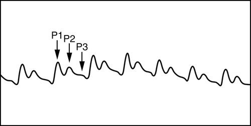
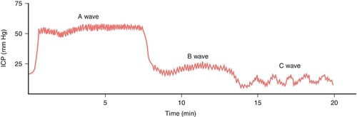
Normally, the ICP waveform has P1, P2, and P3 components, with the amplitude in descending order, specifically P1 > P2 > P3. An increase in P2 > P1 may be indicative of decreased intracranial compliance36,42 as shown in Figure 21-13. However, an elevated P2 and decreased compliance do not always correspond clinically. Additional changes in ICP and waveform morphology are noted in Table 21-7.36,42 Lundberg A and B waves are not easily captured on the typical bedside monitor, since the monitor may not allow visualization of trends over 5 minutes or more37–39 (Figure 21-14).
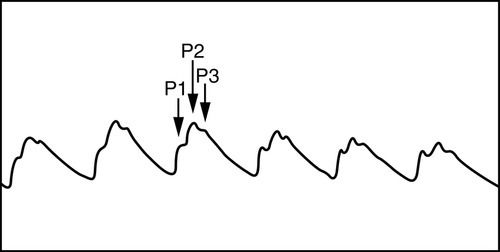
Table 21-7
Intracranial Pressure (ICP) Changes Related to Differing Physiologic Conditions
From Kirkness CJ, Mitchell PH, Burr RI, et al.: Intracranial pressure waveform analysis: clinical and research implications, J Neurosci Nurs 32(5):273, 2000.
Assessment
After leveling and zeroing the transducer and establishing a baseline, the drainage system and the patient are assessed at least every hour. The patient’s neurologic status, ICP, CPP, and the amount and character of the drainage are noted and documented. Any drainage from the insertion site is documented as well. Complications related to the insertion or ventricular drainage must be recorded, including underdrainage or overdrainage, and new intracranial hemorrhage. The rate of CSF drainage must be assessed prior to leaving the external ventricular catheter open initially with frequent observations because of the potential for under or overdrainage.36
The MAP value that is most often used in the calculation of CPP is an arterial line with the transducer at the phlebostatic axis or a blood pressure cuff at the heart level. The arterial line must have an optimal waveform as evidenced by an acceptable square waveform test (see Figure 4-5 in Chapter 4). The same method of blood pressure measurement is used consistently. Some clinicians advocate for measurement of the “cerebral mean arterial pressure” by leveling the arterial line transducer with the foramen of Monro to calculate CPP.37 However, this is controversial and has not gained widespread acceptance.43
Maintenance
Maintenance of an external ventricular catheter includes ongoing assessment of CSF output and ICP and CPP measurements. The hourly CSF drainage rate is generally recommended to approximate the amount of CSF production in an hour for an adult, or approximately 20 milliliters (mL) an hour. Overdrainage may cause headache, formation of a subdural hematoma, development of pneumocephalus, or herniation. Underdrainage may result in deterioration in neurologic status, increased ICP, hydrocephalus, and herniation.36
Leveling of the reference zero on the drainage system with the anatomic reference point (foramen of Monro), is required when the patient’s position changes. Rezeroing is indicated per institutional policy and with each disconnect of the transducer from the bedside monitor cable. High and low pressure alarm limits are set. If the external ventricular catheter is open continuously, alarms may reflect trends but must not be interpreted as the actual ICP value.
Troubleshooting
Among the most common issues with a ventriculostomy catheter is decreased CSF drainage. Gradual slowing of the drainage without an increase in the height of the burette level must be noted before complete blockage and dangerously high ICPs occur. The drainage system may be assessed for patency by slightly lowering the burette—for a very short period—to determine the rate of drainage. Maneuvers that may restore patency include stimulating the patient to cough or repositioning the patient. Depending on institutional policy, the nurse may flush away from the head or change the drainage system if the underdrainage is related to the obstruction in the drainage system and not in the catheter. In some institutions, staff nurses, advanced practice nurses or physicians may have a protocol to flush into the CSF drain with a prescribed small amount of preservative-free sterile normal saline in emergency situations to restore patency. Loss of the ICP waveform may indicate blockage, loose system connections, or possibly transducer failure. A numeric value without a corresponding waveform is of no value.36
Transducer-Tipped Intracranial Pressure Catheters
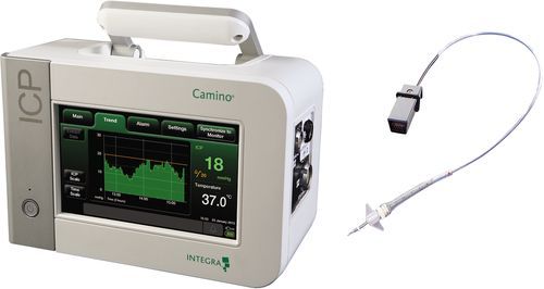
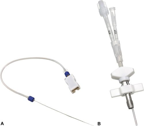
ICP catheters with the transducer in the tip may be fiberoptic, strain gauge, or pneumatic. They are typically placed through cranial bolt into the parenchyma but may also be placed in the surgical site at the time of surgery (Figure 21-15). The fiberoptic transducer-tipped ICP catheters are zeroed prior to insertion and cannot be rezeroed once inserted. Leveling of the catheter and determining the patient’s anatomic reference are not required. Transducer-tipped catheters are most typically attached to a specialized ICP-monitor that displays the patient’s ICP waveform and mean value; a cable connects this monitor with the patient’s bedside monitor for a central alarm and larger view of the waveform.
Two devices, one a pneumatic device, and the other, an electronic chip strain gauge device, may be directly attached to the bedside monitor without an additional ICP monitor. The pneumatic device may be periodically rezeroed after insertion, as needed. At least one manufacturer makes a hybrid-type catheter with a fiberoptic tip and CSF drainage capability. Because the distance between catheter drainage lumens sizes and sensors differ with various manufacturers, it is best practice to close off the ventriculostomy drain to ensure the most accurate ICP reading.
Disadvantages of fiberoptic transducer-tipped catheters include their expense, inability to recalibrate once inserted, easy breakage, inability to drain CSF, and drift, particularly after 5 days. Transducer-tipped catheters are said to be less reliable than an external ventricular catheter and are not MRI compatible.29 In addition, an intraparenchymal ICP catheter placed in the noninjured hemisphere may not adequately reflect increased ICP until the patient’s condition has deteriorated dramatically.38
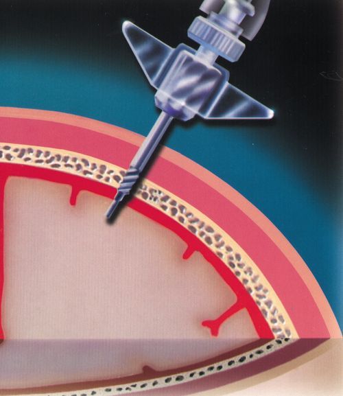
Clinical Procedure
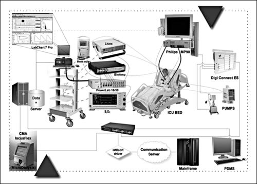
Although the risk of infection with an intraparenchymal transducer-tipped catheter is less than that of an external ventricular catheter, sterile technique must be maintained during insertion. As with the external ventricular catheter, the patient’s hair may be clipped, skin prepared, and drapes applied before the skin incision. The intraparenchymal transducer-tipped fiberoptic catheter is typically placed through a bolt—a hollow cannula—screwed into a burr hole in the skull. The dura is surgically opened through the burr hole, and the catheter is passed through the bolt and dural opening and is positioned in the cerebral cortex (Figure 21-16). Prior to insertion, the catheter is zeroed to atmospheric pressure as indicated on the monitor. Markings on the outside of the catheter indicate the depth of the catheter. The catheter is secured at the desired depth in the bolt with a compression cap and sheath. Monitoring begins immediately. Another parameter that may be measured with the fiberoptic transducer-tipped catheters is brain temperature (TBR), which will be discussed later in this chapter. The catheter, or the monitor that attaches to the catheter, may be connected to the bedside monitor to automatically calculate and display the CPP value, as part of a system of multimodal cerebral monitoring (Figure 21-17).
Indications
The indications for the transducer-tipped catheter are similar to those for the external ventricular catheter except that CSF drainage is not possible unless a hybrid catheter (external ventricular drain and transducer-tipped catheter) is inserted.2
Setup
The setup for the transducer-tipped catheter is less complicated than that for the external ventricular catheter. Steps include (1) gathering the equipment, including the monitor for the catheter; (2) assisting the physician to maintain sterile technique while attaching the catheter to the monitor cable; and (3) holding the cable while the physician zeros the catheter, prior to insertion. Once the catheter is in place, the nurse or physician may provide further protection of the catheter’s position with tape and by attaching the cable to the patient’s gown to prevent the catheter from sliding out of the bolt.
Establishing a Neurologic Baseline
Correct placement of the transducer-tipped catheter will yield an ICP waveform and the corresponding ICP number. A calibration step procedure may be required to connect the ICP monitor to the bedside monitor, and provide a larger display with a central alarm system.10,44 The ICP waveforms are similar to the external ventricular catheter waveforms. ICP and CPP monitoring may begin immediately. Again, identification of the presence of Lundberg A and B waves will be difficult without additional trend monitoring capability. High and low pressure alarms must be set.36,39
Assessment
Neurologic assessment prior to the insertion and afterward provides some assurance that insertion did not cause any harm or that the patient did not deteriorate during the insertion procedure. With each neurologic assessment and observation of the patient’s ICP numeric value and waveform, the nurse notes the depth of the catheter as indicated by the markings. Any changes should be communicated to the physician.
Maintenance
In addition to the assessment described above, the ICP monitor is plugged into the electrical wall current to maintain the battery charge, except during transport to radiology or to the operating room. Drift or inaccurate values may be encountered after 5 days after catheter insertion. Nursing care includes inspection of insertion site and change of dressing based on institutional policy.
Troubleshooting
A broken catheter may be indicated by an error message or loss of waveform on the ICP monitor. Other issues include malposition of the catheter. The nurse is responsible for assessing the position of the catheter based on the visible external markings. Even if the ICP catheter has a numeric display and an adequate waveform, the physician is to be alerted regarding the change in catheter position. The catheter may not be adequately reflecting the ICP at a particular location if it is no longer at the same depth. Loss of battery power or cable connections are common occurrences as well. In the absence of an obviously broken catheter, other options such as changing the ICP monitor or assessing the status of the bedside monitor must be explored prior to removing the catheter and inserting a new one.
Brain Oxygenation
Brain Tissue Oxygenation—PbtO2 Catheter
Direct measurement of focal brain tissue oxygen or brain tissue oxygenation (PbtO2) in a small area of brain tissue is accomplished with a catheter that has a polarographic Clarke-type microelectrode with a semipermeable membrane and electromagnetic features, or a catheter with optical luminescence. Currently, only the polarographic Clarke-type microelectrode catheter (Licox®), is commercially available in the United States to detect focal brain hypoxia.10,44 The Licox brain tissue oxygen monitor triple bolt system is shown in Figure 21-18. The Clarke-type microelectrode catheter requires simultaneous temperature measurement for accurate measurement of the PbtO2.10,42 This particular catheter is available as a combination probe that allows simultaneous monitoring of PbtO2 and brain temperature. Each catheter has its own calibration card, which must be placed in the monitor that connects to the catheter for accuracy.46–48 (Figure 21-19).
Related posts:


Stay updated, free articles. Join our Telegram channel

Full access? Get Clinical Tree


