Key Concepts
 Because insufflation avoids any direct patient contact, there is no rebreathing of exhaled gases if the flow is high enough. Ventilation cannot be controlled with this technique, however, and the inspired gas contains unpredictable amounts of entrained atmospheric air.
 Long breathing tubes with high compliance increase the difference between the volume of gas delivered to a circuit by a reservoir bag or ventilator and the volume actually delivered to the patient.
 The adjustable pressure-limiting (APL) valve should be fully open during spontaneous ventilation so that circuit pressure remains negligible throughout inspiration and expiration.
 Because a fresh gas flow equal to minute ventilation is sufficient to prevent rebreathing, the Mapleson A design is the most efficient Mapleson circuit for spontaneous ventilation.
 The Mapleson D circuit is efficient during controlled ventilation, because fresh gas flow forces alveolar air away from the patient and toward the APL valve.
 The drier the soda lime, the more likely it will absorb and degrade volatile anesthetics.
 Malfunction of either unidirectional valve in a circle system may allow rebreathing of carbon dioxide, resulting in hypercapnia.
 With an absorber, the circle system prevents rebreathing of carbon dioxide at fresh gas flows that are considered low (fresh gas flow ≤ 1 L) or even fresh gas flows equal to the uptake of anesthetic gases and oxygen by the patient and the circuit itself (closed-system anesthesia).
 Because of the unidirectional valves, apparatus dead space in a circle system is limited to the area distal to the point of inspiratory and expiratory gas mixing at the Y-piece. Unlike Mapleson circuits, the circle system tube length does not directly affect dead space.
 The fraction of inspired oxygen (Fio2) delivered by a resuscitator breathing system to the patient is directly proportional to the oxygen concentration and flow rate of the gas mixture supplied to the resuscitator (usually 100% oxygen) and inversely proportional to the minute ventilation delivered to the patient.
Breathing Systems: Introduction
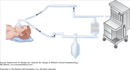
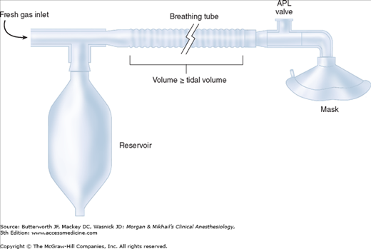
Breathing systems provide the final conduit for the delivery of anesthetic gases to the patient. Breathing circuits link a patient to an anesthesia machine (Figure 3-1). Many different circuit designs have been developed, each with varying degrees of efficiency, convenience, and complexity. This chapter reviews the most important breathing systems: insufflation, draw-over, Mapleson circuits, the circle system, and resuscitation systems.
Most classifications of breathing systems artificially consolidate functional characteristics (eg, the extent of rebreathing) with physical characteristics (eg, the presence of unidirectional valves). Because these seemingly contradictory classifications (eg, open, closed, semiopen, semiclosed) often tend to confuse rather than aid understanding, they are avoided in this discussion.
Insufflation
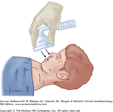
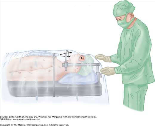
The term insufflation usually denotes the blowing of anesthetic gases across a patient’s face. Although insufflation is categorized as a breathing system, it is perhaps better considered a technique that avoids direct connection between a breathing circuit and a patient’s airway. Because children often resist the placement of a face mask (or an intravenous line), insufflation is particularly valuable during inductions with inhalation anesthetics in children (Figure 3-2). It is useful in other situations as well. Carbon dioxide accumulation under head and neck draping is a hazard of ophthalmic surgery performed with local anesthesia. Insufflation of air across the patient’s face at a high flow rate (>10 L/min) avoids this problem, while not increasing the risk of fire from accumulation of oxygen (Figure 3-3).  Because insufflation avoids any direct patient contact, there is no rebreathing of exhaled gases if the flow is high enough. Ventilation cannot be controlled with this technique, however, and the inspired gas contains unpredictable amounts of entrained atmospheric air.
Open-Drop Anesthesia
Although open-drop anesthesia is not used in modern medicine, its historic significance warrants a brief description here. A highly volatile anesthetic—historically, ether or chloroform—was dripped onto a gauze-covered mask (Schimmelbusch mask) applied to the patient’s face. As the patient inhales, air passes through the gauze, vaporizing the liquid agent, and carrying high concentrations of anesthetic to the patient. The vaporization lowers mask temperature, resulting in moisture condensation and a drop in anesthetic vapor pressure (vapor pressure is proportional to temperature).
Draw‐Over Anesthesia
Draw-over devices have nonrebreathing circuits that use ambient air as the carrier gas, although supplemental oxygen can be used, if available. The devices can be fitted with connections and equipment that allow intermittent positive-pressure ventilation (IPPV) and passive scavenging, as well as continuous positive airway pressure (CPAP) and positive end-expiratory pressure (PEEP).
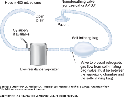
In its most basic application (Figure 3-4), air is drawn through a low-resistance vaporizer as the patient inspires. Patients spontaneously breathing room air and a potent halogenated agent often manifest an oxygen saturation (SpO2) <90%, a situation treated with IPPV, supplemental oxygen, or both. The fraction of inspired oxygen (Fio2) can be supplemented using an open-ended reservoir tube of about 400 mL, attached to a t-piece at the upstream side of the vaporizer. Across the clinical range of tidal volume and respiratory rate, an oxygen flow rate of 1 L/min gives an Fio2 of 30% to 40%, or with 4 L/min, an Fio2 of 60% to 80%. There are several commercial draw-over systems available that share common properties (Table 3-1).
The greatest advantage of draw-over systems is their simplicity and portability, making them useful in locations where compressed gases or ventilators are not available. The presence of the nonrebreathing valve, PEEP valve, and circuit filter close to the patient’s head makes the technique awkward for head and neck surgery and pediatric cases. If the head is draped, the nonrebreathing valve is often covered as well.
Mapleson Circuits
The insufflation and draw-over systems have several disadvantages: poor control of inspired gas concentration (and, therefore, poor control of depth of anesthesia), mechanical drawbacks during head and neck surgery, and pollution of the operating room with large volumes of waste gas. The Mapleson systems solve some of these problems by incorporating additional components (breathing tubes, fresh gas inlets, adjustable pressure-limiting [APL] valves, and reservoir bags) into the breathing circuit. The relative location of these components determines circuit performance and is the basis of the Mapleson classification (Table 3-2).
| Required Fresh Gas Flows | |||||
|---|---|---|---|---|---|
| Mapleson Class | Other Names | Configuration1 | Spontaneous | Controlled | Comments |
| A | Magill attachment | 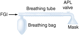 | Equal to minute ventilation (≈80 mL/kg/min) | Very high and difficult to predict | Poor choice during cotrolled ventilaton. Enclosed Magill system is a modification that improves efficiency. Coaxial Mapleson A (Lack breathing system) provides waste gas scavenging. |
| B |  | 2 × minute ventilation | 2-2½ × minute ventilation | ||
| C | Waters’ to-and-fro |  | 2 × minute ventilation | 2-2½ × minute ventilation | |
| D | Bain circuit |  | 2-3 × minute ventilation | 1-2 × minute ventilation | Bain coaxial modification: fresh gas tube inside breathing tube (see Figure 3-7). |
| E | Ayre’s T-piece |  | 2-3 × minute ventilation | 3 × minute ventilation (I:E-1:2) | Exhalation tubing should provide a larger volume than tidal volume to prevent rebreathing. Scavenging is difficult. |
| F | Jackson-Rees’ modification |  | 2-3 × minute ventilation | 2 × minute ventilation | A Mapleson E with a breathing bag connected to the end of the breathing tube to allow controlled ventilation and scavenging. |
Corrugated tubes—made of rubber (reusable) or plastic (disposable)—connect the components of the Mapleson circuit to the patient (Figure 3-5). The large diameter of the tubes (22 mm) creates a low-resistance pathway and a potential reservoir for anesthetic gases. To minimize fresh gas flow requirements, the volume of gas within the breathing tubes in most Mapleson circuits should be at least as great as the patient’s tidal volume.
The compliance of the breathing tubes largely determines the compliance of the circuit. (Compliance is defined as the change of volume produced by a change in pressure.) 
Stay updated, free articles. Join our Telegram channel

Full access? Get Clinical Tree


