FIGURE 28.1 Portable chest x-ray showing proper position of an endotracheal tube, with the tip located midway between the thoracic inlet and the carina.
Migration of Tubes
Endotracheal tubes can migrate distally, and enter the right mainstem bronchus (which runs a straight course down from the trachea). What can happen next is shown in Figure 28.2; i.e., selective ventilation of one lung results in progressive atelectasis in the non-ventilated lung.
There are two measures that can reduce the incidence of endotracheal tube migration. First, for orotracheal intubations, don’t allow the tip of endotracheal tube to advance further than 21 cm from the teeth in women and 23 cm from the teeth in men (3). Second, monitor the position of the endotracheal tube with periodic chest x-rays, and keep the tip of the tube at least 3 cm above the carina.
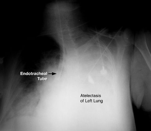
FIGURE 28.2 Portable chest x-ray showing the tip of an endotracheal tube in the right mainstem bronchus. Opacification of the left hemothorax represents atelectasis of the left lung.
Laryngeal Damage
The risk for laryngeal injury with endotracheal tubes is a major concern, and is one of the reasons for performing tracheostomies when prolonged intubation is anticipated. The spectrum of laryngeal damage includes ulceration, granulomas, vocal cord paresis, and laryngeal edema. Some type of laryngeal damage is usually evident after 72 hours of translaryngeal intubation (4), and laryngeal edema is reported in 5% of cases. Fortunately, most cases of laryngeal injury do not result in significant airways obstruction or permanent injury, and the problem resolves within weeks after extubation (5). The problem of laryngeal edema after extubation is described in Chapter 30.
Subglottic Drainage Tubes
The prominent role played by aspiration of mouth secretions in the pathogenesis of ventilator-associated pneumonia has led to the introduction of specially designed endotracheal tubes capable of draining mouth secretions that accumulate just above the inflated cuff. These tubes can reduce the incidence of ventilator-associated pneumonia (6), and they are described in more detail in the next chapter.
Tracheostomy
Tracheostomy is preferred in patients who require prolonged mechanical ventilation (>2 weeks). There are several advantages with a tracheostomy, including greater patient comfort, easier access to the airways, and reduced risk of laryngeal injury.
Tracheostomy Timing
The optimal time for performing a tracheostomy has been debated for years. Recent studies comparing early tracheostomy (one week after intubation) with late tracheostomy (two weeks after intubation) have shown the following:
1. Early tracheostomy does not reduce the incidence of ventilator-associated pneumonia, and does not reduce the mortality rate (7,8).
2. Early tracheostomy does reduce sedative requirements and promote early mobilization (8).
Based on the pneumonia and mortality data, tracheostomy is recommended after 2 weeks of endotracheal intubation (9). If one considers patient comfort, it is not unreasonable to consider tracheostomy after 7–10 days of intubation, if there is little chance of extubation in the following week.
Techniques
The traditional method of performing a tracheotomy as an open surgical procedure has been replaced in popularity by percutaneous dilatational tracheostomy, where a guidewire is passed through a small needle puncture in the anterior wall of the trachea, and is used to advance a tracheostomy tube into the tracheal lumen (10). (This is analogous to the Seldinger technique for inserting central venous catheters, shown in Figure 1.5 on page 11.) This technique is performed at the bedside, and is associated with less blood loss and fewer local infections than surgically created tracheostomies (9,11).
The technique known as cricothyroidotomy is used only for emergency access to the airway. The trachea is entered through the cricothyroid membrane, just below the larynx, and there is high incidence of laryngeal injury and subglottic stenosis. Patients who survive following a cricothyroidotomy should have a regular tracheostomy (surgical or percutaneous) as soon as they are stable (12).
Complications
The morbidity and mortality associated with tracheostomy has declined in recent years. Combining surgical and percutaneous tracheostomy, the mortality rate is less than 1%, and immediate complications (i.e., bleeding and infection) occur in less than 5% of cases (11,12).
ACCIDENTAL DECANNULATION: One acute complication that deserves mention is accidental decannulation. If the tracheostomy tube is dislodged before the stoma tract is mature (which takes about one week) the tract closes quickly, and blind reinsertion of the tube can create false tracts. When a tracheostomy tube is dislodged within a few days of insertion, the patient should be reintubated before attempting to reinsert the tracheostomy tube.
TRACHEAL STENOSIS: The most feared complication of tracheostomy is tracheal stenosis, which is a late complication that appears in the first 6 months after the tracheostomy tube is removed. Most cases of tracheal stenosis occur at the site of the tracheal incision, and are the result of tracheal narrowing after the stoma closes. The incidence of tracheal stenosis ranges from zero to 15% in individual reports (12), but most cases are asymptomatic. The risk of tracheal stenosis is the same with surgical and percutaneous tracheostomies (9).
Cuff Management
Positive pressure ventilation requires a seal in the trachea that prevents gas from escaping out through the larynx. This is created by inflating the balloon (called a cuff) that surrounds the distal portion of the tracheal tube. A tracheostomy tube with an inflated cuff is shown in Figure 28.3. The cuff is attached to a pilot balloon that has a one-way valve. A syringe is attached to the pilot balloon and air is injected into the cuff until there is no audible leak around the cuff. (The pilot balloon will inflate as the cuff inflates.)
The pressure in the cuff (measured with a pressure gauge attached to the pilot balloon) should not exceed 25 mm Hg (13). This pressure limit is based on the assumption that the capillary hydrostatic pressure in the wall of the trachea is 25 mm Hg, and thus external (cuff) pressures above 25 mm Hg can compress the underlying capillaries and produce ischemic injury and tracheal necrosis. Fortunately, the elongated design of cuffs allows for greater dispersion of pressure, and also allows for a tracheal seal at relatively low pressures.
Cuff Leaks
Cuff leaks are usually detected by audible sounds during lung inflation (created by gas flowing through the vocal cords). Cuff leaks are rarely caused by disruption of the cuff (14), and are usually the result of nonuniform contact between the cuff and the wall of the trachea, or dysfunction of the valve on the pilot balloon.
TROUBLESHOOTING: If a cuff leak is audible, the patient should be separated from the ventilator and the lungs should be manually inflated with an anesthesia bag. If the cuff leak involves an endotracheal tube, check the position of the tube to determine if the tube is coming out of the trachea. If this is a possibility, you can deflate the cuff and advance the tube. If this is unsuccessful, the tube should be replaced (or a fiber-optic instrument can be advanced through the tube to make sure it is still in the lungs). Air should never be added to the cuff blindly because the tube may be coming out of the trachea, and cuff inflation will damage the vocal cords. If the cuff leak involves a tracheostomy tube, air can be added to the cuff in an attempt to produce a seal. If this eliminates the leak, the cuff pressure should be measured, and should be ≤25 mm Hg. If the cuff pressure is above 25 mm Hg, or the leak persists despite adding volume, the tracheostomy tube should be replaced (with a larger diameter tube, if possible).
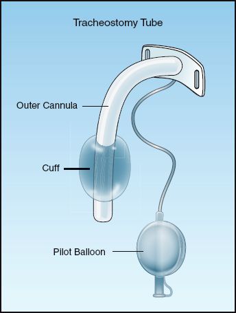
FIGURE 28.3 A tracheostomy tube with an inflated cuff.
AIRWAY CARE
Suctioning
Routine suctioning to clear secretions has been a standard practice in the care of ventilator-dependent patients. However, the inner surface of artificial airways become colonized with biofilms containing pathogenic organisms (see Figure 28.4), and passing a suction catheter through the tubes can dislodge these biofilms and inoculate the lungs with pathogenic organisms (15,16). As a result, endotracheal suctioning is no longer recommended as a routine procedure, but should be performed only when respiratory secretions are present (17).
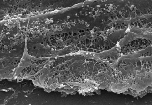
FIGURE 28.4 Electron micrograph showing a biofilm on the inner surface of an endotracheal tube. Image from Reference 16.
Saline Instillation
Saline is often instilled into the trachea to facilitate the clearing of secretions, but this practice is no longer advised as a routine procedure (17) for two reasons: (a) saline will not liquefy or reduce the viscosity of respiratory secretions (as described next), and (b) saline can dislodge pathogenic organisms colonizing the inner surface of tracheal tubes. One study has shown that injection of 5 mL of saline can dislodge up to 300,000 colonies of viable bacteria from the inner surface of endotracheal tubes (18).
Viscosity of Respiratory Secretions
The respiratory secretions create a blanket that covers the mucosal surface of the airways. This blanket has a hydrophilic (water soluble) layer, and a hydrophobic (water insoluble) layer. The hydrophilic layer faces inward, and keeps the mucosal surface moist. The hydrophobic layer faces outward, towards the lumen of the airways. This outer layer is composed of a meshwork of mucoprotein strands (called mucus threads) held together by disulfide bridges. This meshwork traps particles and debris in the airways, and the combination of the mucoprotein meshwork and the trapped debris is what determines the viscoelastic behavior of the respiratory secretions. Since the layer that contributes to the viscosity of respiratory secretions is not water soluble, saline will not reduce the viscosity of respiratory secretions. (Adding saline to thick, respiratory secretions is like pouring water over grease.)
The accumulation of viscous secretions can result in a condition like the one shown in Figure 28.5, where a tenacious “plug” is completely ob-structing a major airway. In this situation, a mucolytic agent like N-Acetylcysteine (Mucomyst) can help to disrupt the plug and relieve the obstruction. N-acetylcysteine (NAC) is a sulfhydryl-containing tripeptide that is better known as the antidote for acetaminophen overdose, but it is also a mucolytic agent that acts by disrupting the disulfide bridges between mucoprotein strands in sputum (19). The drug is available in a liquid preparation (10 or 20% solution) that can be given as an aerosol spray, or injected directly into the airways (Table 28.1). Aerosolized NAC should be avoided when possible because it is irritating to the airways and can provoke coughing and bronchospasm (particularly in asthmatics). Direct instillation of NAC into the tracheal tube is preferred, especially when there is an obstruction.
Table 28.1 Mucolytic Therapy with N-Acetylcysteine (NAC)
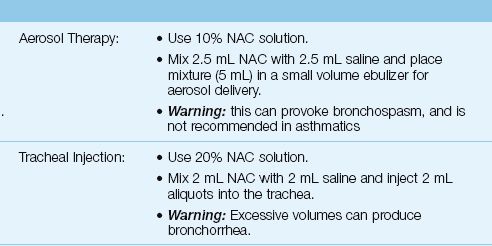
If intratracheal injection of NAC does not relieve an obstruction, bronchoscopy should be performed (the NAC is then applied directly to the mucous plug). Following relief of the obstruction, NAC can be instilled two or three times a day for the next day or two. Daily use of NAC is not advised because the drug solution is hypertonic (even with the saline additive) and can provoke bronchorrhea.
ALVEOLAR RUPTURE
One of the manifestations of ventilator-induced lung injury is alveolar distension and volutrauma, and one of the clinical consequences of volutrauma is alveolar rupture with the escape of gas from the distal airspaces. This form of injury, which is mistakenly called pulmonary barotrauma, occurs in up to 25% of patients receiving mechanical ventilation (20).
Clinical Presentation
Escape of gas from the alveoli can produce a variety of clinical manifestations. The alveolar gas can dissect along tissue planes and produce pulmonary interstitial emphysema, and air can move into the mediastinum and produce pneumomediastinum. Mediastinal gas can move into the neck to produce subcutaneous emphysema, or can pass below the diaphragm to produce pneumoperitoneum. Finally, if the rupture involves the visceral pleura, gas will collect in the pleural space and produce a pneumothorax. Each of these entities can occur alone or in combination (20,21).
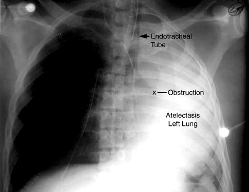
FIGURE 28.5 Portable chest x-ray of an intubated patient showing atelectasis of the left lung, which is usually caused by a mucous plug in the left mainstem bronchus.
Pneumothorax
Radiographic evidence of pneumothorax occurs in 5 to 15% of ventilator-dependent patients (20,21).
Clinical Presentation
Clinical manifestations are either absent, minimal, or nonspecific. The most valuable clinical sign is subcutaneous emphysema in the neck and upper thorax, which is pathognomonic of alveolar rupture. Breath sounds are unreliable in ventilator-dependent patients because sounds transmitted from the ventilator tubing can be mistaken for airway sounds.
Radiographic Detection
The radiographic detection of pleural air can be difficult in the supine position, because pleural air does not collect at the lung apex when patients are supine (22). Figure 28.6 illustrates this difficulty. In this case of a traumatic pneumothorax, the chest x-ray is unrevealing, but the CT scan reveals an anterior pneumothorax on the left. Pleural air will collect in the most superior region of the hemithorax and, in the supine position, this region is just anterior to both lung bases. Therefore, basilar and subpulmonic collections of air are characteristic of pneumothorax in the supine position (22).
REDUNDANT SKIN FOLDS: When the film cartridge used for portable chest x-rays is placed under the patient, the skin on the back can fold over on itself, and the edge of this redundant skin fold creates a radiographic shadow that can be mistaken for a pneumothorax. The radiographic appearance of a redundant skin fold is shown in Figure 28.7. Note that there is a gradual increase in radiodensity that produces a wavy line. The gradual increase in density is produced by the skin that is folded back on itself. A pneumothorax would appear as a sharp white line with dark shadows (air) on either side.
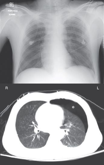
FIGURE 28.6 A portable chest x-ray and CT image of the thorax in a young male with blunt trauma to the chest. An anterior pneumothorax is evident on the CT image (indicated by the asterisk) but is not apparent on the portable chest x-ray.
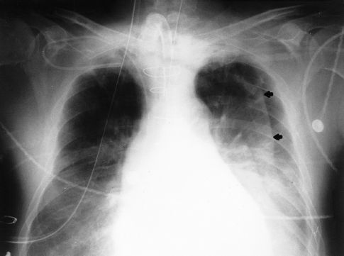
FIGURE 28.7 Portable chest x-ray showing a wavy line in the left hemithorax. This line is the edge of a redundant skin fold, and not the edge of the lung.
Pleural Evacuation
Evacuation of pleural air is accomplished by inserting a chest tube through the fourth or fifth intercostal space along the mid-axillary line. The tube should be advanced in an anterior and superior direction (because this is where pleural air collects in the supine position). The pleural space is drained of fluid and air using a three-chamber system like the one shown in Figure 28.8 (23).
Collection Bottle
The first bottle in the system collects fluid from the pleural space and allows air to pass through to the next bottle in the series. Because the inlet of this chamber is not in direct contact with the fluid, the pleural fluid that is collected does not impose a back pressure on the pleural space.
Water-Seal Bottle
The second bottle acts as a one-way valve that allows air to escape from the pleural space but prevents air from entering the pleural space. This one-way valve is created by submerging the inlet tube under water. This imposes a back-pressure on the pleural space that is equal to the depth that the tube is submerged. The positive pressure in the pleural space then prevents atmospheric air (at zero pressure) from entering the pleural space. The water thus “seals” the pleural space from the surrounding atmosphere. This water-seal pressure is usually 2 cm H2O.
Air that is evacuated from the pleural space passes through the water in the second bottle and creates bubbles. Thus, the presence of bubbles in the water-seal chamber is evidence of a continuing bronchopleural air leak.
Suction-Control Bottle
The third bottle in the system is used to set a maximum limit on the negative suction pressure that is imposed on the pleural space. This maximum pressure is determined by the height of the water column in the air inlet tube. Negative pressure (from wall suction) draws the water down the air inlet tube, and when the negative pressure exceeds the height of the water column, air is entrained from the atmosphere. Therefore, the pressure in the bottle can never become more negative than the height of the water column in the air inlet tube.
Water is added to the suction-control chamber to achieve a water level of 20 cm. The wall suction is then activated and slowly increased until bubbles appear in the water. This bubbling indicates that atmospheric air is being entrained, and thus the maximum negative pressure has been achieved. The continuous bubbling causes water evaporation, so it is imperative that the height of the water in this chamber is checked periodically, and more water is added when necessary.
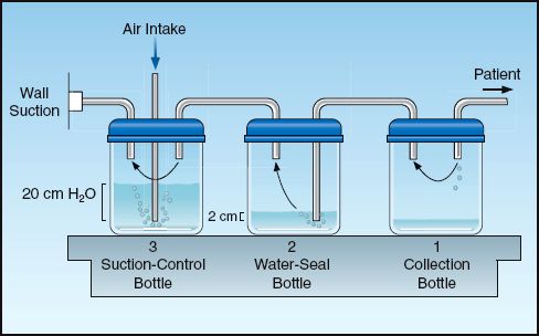
FIGURE 28.8 A standard pleural drainage system for evacuating air and fluid from the pleural space.
Why Suction?
The practice of using suction to evacuate pleural air is often unnecessary and potentially harmful. Although there is a perception that suction will help the lungs reinflate, the lungs will reinflate without the use of suction. Furthermore, creating a negative pressure in the pleural space also creates a higher transpulmonary pressure (the pressure difference between alveoli and the pleural space), and this increases the rate of the air flowing through a bronchopleural fistula. Thus applying suction to the pleural space increases bronchopleural air leaks, and this can prevent bronchopleural fistulas from closing. If a persistent air leak is present when suction is applied to the pleural space, the suction should be discontinued. Any air that collects in the pleural space will continue to be evacuated when the pleural pressure becomes more positive than the water-seal pressure.
INTRINSIC (OCCULT) PEEP
Intrinsic, occult PEEP (also called auto-PEEP) is described in Chapter 24 (see pages 477–479) and in Chapter 25 (see pages 490–491). The features of intrinsic PEEP are illustrated in Figure 28.9. This pressure is the result of incomplete exhalation, and can occur in patients with severe airflow obstruction, or during mechanical ventilation that is too rapid to allow complete exhalation (24). During conventional mechanical ventilation, intrinsic PEEP is probably universal in patients with severe asthma and COPD (25,26), while it is also common in patients with ARDS (27), although at low levels (<3 cm H2O). It is important to emphasize that intrinsic PEEP is not apparent when monitoring airway pressures (hence the term “occult PEEP”).
Adverse Effects
Intrinsic PEEP has several adverse effects, which are summarized below (24). As is the case with applied PEEP, many of these adverse effects are not the result of the PEEP level, but rather are due to the influence of PEEP on the end-inspiratory alveolar pressure and the mean intrathoracic pressure.
1. Intrinsic PEEP increases mean intrathoracic pressure, which impairs venous return and can decrease cardiac output.
2. The hyperinflation that produces intrinsic PEEP in patients with severe airflow obstruction can increase the work of breathing when the region of tidal breathing moves to the upper flat portion of the pressure-volume curve (see Figure 24.4 on page 478). (To appreciate this effect, take a deep breath, and then try to breathe in further.)
3. Intrinsic PEEP increases end-inspiratory alveolar pressure, which increases the risk of volutrauma and alveolar rupture.
4. When intrinsic PEEP goes undetected, the increase in end-inspiratory alveolar pressure (plateau pressure) is misinterpreted as a decrease in the compliance of the lungs and chest wall. When thoracic compliance is calculated (see page 492), the total PEEP level (applied PEEP plus intrinsic PEEP) must be subtracted from the end-inspiratory alveolar (plateau) pressure.
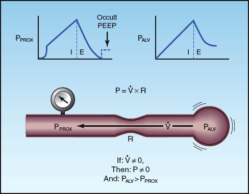
FIGURE 28.9 The features of intrinsic PEEP resulting from incomplete exhalation. The presence of airflow (V.) at end-expiration indicates a pressure drop from the alveolus (PALV) to the proximal airways (PPROX). As shown at the top of the figure, the proximal airway pressure returns to zero at end-expiration while the alveolar pressure remains positive, hence the term occult PEEP. The upper left panel illustrates the end-expiratory occlusion method for measuring occult PEEP.
5. Intrinsic PEEP can be transmitted into the superior vena cava, resulting in the mistaken impression that end-diastolic (transmural) pressure has increased.
Monitoring Intrinsic PEEP
Intrinsic PEEP is easy to detect but difficult to quantify. The easiest method of detection is inspecting the expiratory flow waveform for the presence of airflow at the end of expiration (see Figure 24.5 on page 479). If intrinsic PEEP is evident on the expiratory flow waveform, the level of intrinsic PEEP can be measured with the end-expiratory occlusion method.
End-Expiratory Occlusion
Occlusion of the expiratory circuit at the end of expiration will “unmask” intrinsic PEEP, as shown in Figure 28.9. Accuracy requires that the occlusion occur at the very end of expiration, and this cannot be timed properly if patients are breathing spontaneously. Therefore, the end-expiratory occlusion method can only be performed in the patients who are not triggering ventilator breaths.
Management
The maneuvers used to prevent or reduce hyperinflation and intrinsic PEEP are all directed at promoting alveolar emptying during expiration. These maneuvers include reducing the tidal volume, increasing the inspiratory flow rate, reducing the inspiratory time (in pressure control ventilation), and reducing the respiratory rate, if possible. Some of these maneuvers will reduce the minute ventilation, which may not be desirable.
Applied PEEP
The addition of external PEEP can reduce hyperinflation (and intrinsic PEEP) by holding the small airways open at end-expiration. The level of applied PEEP must be enough to counterbalance the pressure causing small airways collapse (the closing pressure) but should not exceed the level of intrinsic PEEP (so that it does not impair expiratory flow) (28). To accomplish this, the level of applied PEEP should match the level of intrinsic PEEP. Since intrinsic PEEP will be difficult to quantify in spontaneously breathing patients, an alternative method in these patients is to monitor the response of the end-expiratory airflow to applied PEEP; i.e., if the applied PEEP reduces or eliminates end-expiratory flow, then it is reducing the level of intrinsic PEEP. Although the end result is still PEEP (applied PEEP instead of intrinsic PEEP), the applied PEEP will help to reduce the risk of atelectrauma from repetitive opening and closing of small airways at end-expiration.
A FINAL WORD
The patient’s clinical course in the first few days of mechanical ventilation will give you a fairly accurate indication of what is coming. If the patient is not improving, proceed to a tracheostomy as soon as it can be done safely. Most of the day-to-day management of the ventilator-dependent patient involves vigilance for adverse events (e.g., pneumothorax). You will learn that, in many cases, you are not the one controlling the course of the patient’s illness.
REFERENCES
Endotracheal Tubes
1. Gray AW. Endotracheal tubes. Crit Care Clin 2003; 24:379–387.
2. Goodman LR. Pulmonary support and monitoring apparatus. In: Goodman LR, Putman CE, eds. Critical care imaging. 3rd ed. Philadelphia: WB Saunders, 1992; 35–59.
3. Owen RL, Cheney FW. Endotracheal intubation: a preventable complication. Anesthesiology 1987; 67:255–257.
4. Gallagher TJ. Endotracheal intubation. Crit Care Clin 1992; 8:665–676.
5. Colice GL. Resolution of laryngeal injury following translaryngeal intubation. Am Rev Respir Dis 1992; 145:361–364.
6. Muscedere J, Rewa O, Mckechnie K, et al. Subglottic secretion drainage for the prevention of ventilator-associated pneumonia: a systematic review and meta-analysis. Crit Care Med 2011; 39:1985–1991.
Tracheostomy
7. Terragni PP, Antonelli M, Fumagalli R, et al. Early vs. late tracheotomy for prevention of pneumonia in mechanically ventilated adult ICU patients. JAMA 2010; 303:1483–1489.
8. Trouillet JL, Luyt CE, Guiguet M, et al. Early percutaneous tracheotomy versus prolonged intubation of mechanically ventilated patients after cardiac surgery: A randomized trial. Ann Intern Med 2011; 154:373–383.
9. Freeman BD, Morris PE. Tracheostomy practice in adults with acute respiratory failure. Crit Care Med 2012; 40:2890–2896.
10. Ciagla P. Technique, complications, and improvements in percutaneous dilatational tracheostomy. Chest 1999; 115:1229–1230.
11. Freeman BD, Isabella K, Lin N, Buchman TG. A meta-analysis of prospective trials comparing percutaneous and surgical tracheostomy in critically ill patients. Chest 2000; 118:1412–1418.
12. Tracheotomy: application and timing. Clin Chest Med 2003; 24:389–398.
13. Heffner JE, Hess D. Tracheostomy management in the chronically ventilated patient. Clin Chest Med 2001; 22:5; 10:561–568.
14. Kearl RA, Hooper RG. Massive airway leaks: an analysis of the role of endotracheal tubes. Crit Care Med 1993; 21:518–521.
Airway Care
15. Adair CC, Gorman SP, Feron BM, et al. Implications of endotracheal tube biofilm for ventilator-associated pneumonia. Intensive Care Med 1999; 25:1072–1076.
16. Gil-Perontin S, Ramirez P, Marti V, et al. Implications of endotracheal tube biofilm in ventilator associated pneumonia response: a state of concept. Crit Care 2012; 16:R93 (available at ccforum.com/content/16/3/R93).
17. AARC Clinical Practice Guideline. Endotracheal suctioning of mechanically ventilated patients with artificial airways 2010. Respir Care 2010; 55:758–764.
18. Hagler DA, Traver GA. Endotracheal saline and suction catheters: sources of lower airways contamination. Am J Crit Care 1994; 3:444–447.
19. Holdiness MR. Clinical pharmacokinetics of N-acetylcysteine. Clin Pharma-cokinet 1991; 20:123–134.
Alveolar Rupture
20. Gammon RB, Shin MS, Buchalter SE. Pulmonary barotrauma in mechanical ventilation. Chest 1992; 102:568–572.
21. Marcy TW. Barotrauma: detection, recognition, and management. Chest 1993; 104:578–584.
22. Tocino IM, Miller MH, Fairfax WR. Distribution of pneumothorax in the supine and semirecumbent critically ill adult. Am J Radiol 1985; 144:901–905.
23. Kam AC, O’Brien M, Kam PCA. Pleural drainage systems. Anesthesia 1993; 48:154–161.
Intrinsic (Occult) PEEP
24. Marini JJ. Dynamic hyperinflation and auto-positive end expiratory pressure. Am J Respir Crit Care Med 2011; 184:756–762.
25. Blanch L, Bernabe F, Lucangelo U. Measurement of air trapping, intrinsic positive end-expiratory pressure, and dynamic hyperinflation in mechanically ventilated patients. Respir Care 2005; 50:110–123.
26. Shapiro JM. Management of respiratory failure in status asthmaticus. Am J Respir Med 2002; 1:409–416.
27. Hough CL, Kallet RH, Ranieri M, et al. Intrinsic positive end-expiratory pressure in Acute Respiratory Distress Syndrome (ARDS) Network subjects. Crit Care Med 2005; 33:527–532.
28. Tobin MJ, Lodato RF. PEEP, autoPEEP, and waterfalls. Chest 1989; 96:449–451.


Stay updated, free articles. Join our Telegram channel

Full access? Get Clinical Tree


