DEFINITION AND SCOPE
Use of Diagnostic Imaging to Improve Safety
Diagnostic imaging is used broadly across all of medical practice to investigate the anatomic basis for new onset of many symptoms indicative of disease, and pain is one of the most common of those presenting symptoms. Indeed, diagnostic imaging is the cornerstone of establishing anatomic diagnoses responsible for pain, such as new onset of radicular pain associated with intervertebral disc herniation. A broad discussion of the use of diagnostic imaging is beyond the scope of this chapter, but several directed examples where diagnostic imaging can provide critical information in planning treatment will be reviewed.
There is moderate evidence from controlled trials that epidural injection of steroids can speed the resolution of radicular pain in the early months after acute lumbar disc herniations.1–3 The technique is now in widespread use. By extension from the evidence for lumbar disc herniation, this technique has also been used to treat radicular pain associated with thoracic and cervical disc herniations as well as pain associated with spinal stenosis. Two decades ago, use of diagnostic imaging to establish the exact anatomic level of disc herniation was becoming more commonplace. However, most practitioners actually performing epidural injections were doing so without expertise in interpreting these imaging studies, and they were most commonly using the blind loss-of-resistance technique to identify the epidural space.4 Based on little scientific evidence, conventional wisdom at that time held that the injection should be placed at the level of the disc herniation to produce the best benefit. Thus, many practitioners simply placed these epidural injections based on the radiologists report: if there was a disc herniation at the C6/7 level, then the injection was placed at that level. Reports of spinal cord injury occurring during these injections began to appear, and the connection between contact with the spinal cord and high-grade spinal stenosis was established.4 Indeed, in high-grade stenosis of the central spinal canal arising from any cause, there may be complete effacement of the CSF and epidural fat, with direct pressure on the spinal cord. This is precisely the case in a small proportion of patients with large disc herniations (Fig. 30-1). In these cases, it is critical to recognize the lack of adequate room in the posterior epidural space to allow for safe needle entry and placement of the epidural steroid. Thus the use of diagnostic imaging and review of the images prior to attempting epidural injection is now routine. When there is severe canal stenosis, injection at the stenotic levels can be readily avoided by using fluoroscopy to precisely guide needle placement at an anatomic level where prior diagnostic imaging has demonstrated adequate room for needle entry.
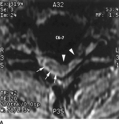
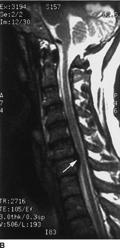
FIGURE 30-1. Cervical MRI in a patient with a large C6/7 disc herniation that causes significant stenosis of the central spinal canal. This patient developed neuropathic pain suggestive of minor spinal cord injury during epidural steroid injection conducted using a blind technique at the C6/7 level. Review of diagnostic imaging studies before injection would have identified this high-grade stenosis and use of fluoroscopy to select an intervertebral level where the stenosis was less severe may have prevented this injury.A: Axial T1-weighted magnetic resonance image at the C6/7 level. There is a large central herniated intervertebral disk that lateralizes to the left (arrowheads). The spinal cord is displaced toward the right posterior portion of the spinal canal (arrows). B: Sagittal T2-weighted image at the midline of the cervical spine. There is a large disk herniation at the C6/7 level, causing posterior displacement of the spinal cord (arrow) and effacement of the cerebrospinal fluid signal anterior to the spinal cord. (Reproduced from Field J, Rathmell JP, Stephenson JH, et al. Neuropathic pain following cervical epidural steroid injection. Anesthesiology 2000;93:885–888, with permission.)
Neurolytic celiac plexus block is another technique that has moderate scientific evidence from controlled trials supporting the ability to reduce pain and the need for analgesic use in patients with pain associated with intra-abdominal malignancies, particularly pancreatic cancer. The complications associated with this technique have been detailed in Chapter 23 and include renal trauma, trauma to the large vessels of the abdomen, and pneumothorax. The use of diagnostic imaging for identification and staging of pancreatic cancer is standard practice worldwide; thus, these detailed anatomic studies are almost universally available at the time patients are referred for celiac plexus neurolysis. Close analysis of the diagnostic studies can assist in the planning stages to guide the spinal level of needle entry as well as the angle and depth of needle penetration. These planning measurements can be easily made on the diagnostic images and used to guide optimal needle placement during celiac plexus block done subsequently using either CT of fluoroscopy for guidance (Fig. 30-2). In this way, existing diagnostic studies can be used in the planning stages to avoid adjacent structures, thereby improving safety.
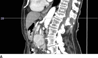
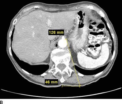
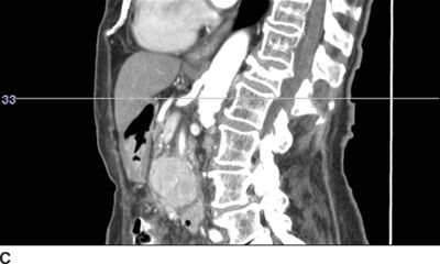
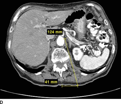
FIGURE 30-2. Use of diagnostic CT angiography study of the abdomen in a patient referred for celiac plexus block to plan position and depth of needle placement. The diagnostic CT angiogram can be used to determine the safest position to place needles and plan the final depth on needle insertion; these measurements can then be used to carry out the block with either fluoroscopy or CT guidance. A: Sagittal image through the celiac artery. The celiac artery arises from the aorta at the junction between the L1 and L2 vertebrae. This patient has a vertebral compression fracture of the L1 vertebral body. The line through this image corresponds with the axial image in Figure 30-2B. B: Axial image through the origin of the celiac artery from the anterior aorta, the typical site for celiac plexus block. Modern CT imaging software can be used to measure the distance from the anterolateral surface of the aorta to the skin surface (126 mm) and from the spinous process to the point of needle entry (46 mm). This patient has significant flattening of the diaphragms from chronic obstructive pulmonary disease. Performing the celiac plexus block at the level of L1 as shown will result in the needle traversing the pleura en route to the anterolateral surface of the aorta and is likely to result in a pneumothorax. C: Sagittal image 1 cm inferior to the origin of the celiac artery. The line through this image corresponds with the axial image in Figure 30-2D. D: Axial image 1 cm inferior to the origin of the celiac artery from the anterior aorta, below the inferior reflections of the pleura. The distance from the anterolateral surface of the aorta to the skin surface (124 mm) and from the spinous process to the point of needle entry (41 mm); similar measurements can be made for placement of the needle on the right side. Performing the celiac plexus block somewhat inferior to the celiac artery in this patient was carried out successfully: the needles were well below the pleura at this level.
Use of Image Guidance to Improve Safety
The earliest studies that point toward the superiority of image guidance in increasing the precision of epidural localization examine the success of the blind technique. One of the most quoted studies appeared in 1980 and demonstrated that using a blind technique correctly identified the epidural space when using the loss of resistance technique in only 30% of cases.5 This study has been criticized, as the injectionists in the study were not frequent users of the loss of resistance technique. Indeed, when experienced physicians placed epidurals in the setting of labor and delivery, the success rose to 61.7% in comparison to a success rate of 47.7% in those who had performed <10 epidural injections previously.6 In contrast, subsequent investigators reported a successful epidural injection in 97.5% of cases performed using fluoroscopic guidance and the caudal route.7 Radiographic guidance can be used to display images in multiple planes at all spinal levels, and with use of radiographic contrast, the epidural space can be identified the vast majority of time (Figs. 30-3 and 30-4). The use of radiographic guidance using a coaxial technique can certainly improve the precision of needle placement, reducing or eliminating the need for redirection of the needle to reach the epidural space.8 By aligning the axis of the x-ray beam with the final radiographic target—for example, the epidural space in the midline—the skin directly overlying this target can be anesthetized, and a needle passed directly from the skin’s surface to the target in a single pass. Anteroposterior radiographs demonstrate the needle position from lateral to medial and cephalad to caudad; lateral radiographs demonstrate the needle’s depth from the skin’s surface (Figs. 30-3 and 30-4). However, only bony structures can be identified using fluoroscopy; thus, final needle advancement into the epidural space still requires use of the loss-of-resistance technique. Once the needle is in final position within the epidural space, the location can be confirmed by injecting a small volume of radiographic contrast. If the contrast spreads in a characteristic pattern without evidence of flow into a vascular structure, then the epidural location can be confirmed (Fig. 30-5). However, identification of intravascular needle location using fluoroscopy requires use of a live or real-time technique rather than single static images, as any contrast that flows into a blood vessel will be carried away within the blood stream and will no longer be seen on static images taken subsequently (see further discussion below). The other difficulty with use of radiographic guidance is the appearance of confusing patterns of contrast spread, particularly in patients who have had prior surgery and have fusion masses along the bony spine or scarring in the epidural space; we will discuss these problems in detail below. Thus, it is clear that the use of radiographic guidance does not assure the safety of image-guided injections, but the use of these techniques has strong intellectual appeal, indeed strong face validity as a means to improve safety: if you can directly visualize or more precisely infer the position of critical structures like blood vessels and the spinal cord, then it stands to reason that these structures can be avoided with the use of image guidance. Nonetheless, images can be confusing, practitioners have varying levels of skill, and despite the intuitive appeal of this approach, there is little evidence to support improved safety with image guidance. Indeed, in a recent study published by the American Society of Anesthesiologists (ASA) that examined closed malpractice claims, a subgroup of patients who sustained spinal cord injuries during the course of cervical spinal injections were examined in detail.9 The use of radiographic guidance was more common in those who sustained spinal cord injuries than in those who had cervical procedures performed without radiographic guidance. It is tempting to jump to the conclusion that radiographic guidance made spinal cord injury more likely. However, it is equally plausible that the types of injections that led to spinal cord injury (in this case, cervical epidural steroid injection using an interlaminar technique) were simply done more often with radiographic guidance—thus the higher proportion of injuries associated with radiographic guidance. Without knowing how many total injections were done with and without radiographic guidance, we have no means to know the actual incidence of injury with each method of performing these injections. Nonetheless, the ASA Closed Claims report clearly demonstrates that direct trauma to the spinal cord can occur during the conduct of transforaminal injections, interlaminar epidural injections, and trigger point injections carried out at the level of the cervical spine even when image guidance is used.
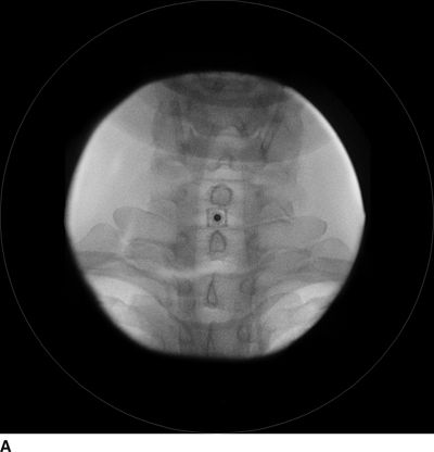
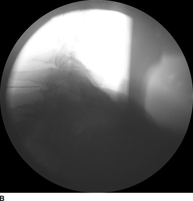
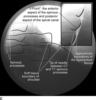
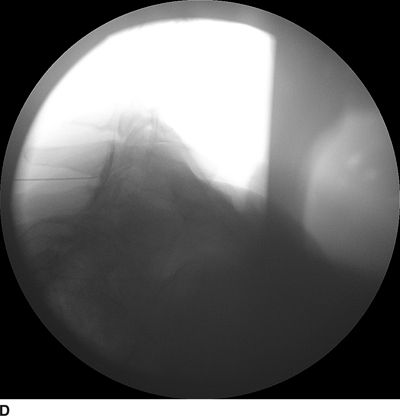
FIGURE 30-3. Radiographic identification of the cervical epdiural space. A: AP radiograph of the cervical spine during cervical interlaminar injection. A 20-gauge Tuohy needle is in position between the C7 and T1 laminae and spinous processes. The needle hub is projected directly over the needle tip and is positioned between the spinous processes. B: Lateral radiograph of the cervical spine near the cervicothoracic junction during interlaminar cervical epidural injection. A 22-gauge Tuohy needle is in place in the C7/T1 interspace extending toward the dorsal epidural space. C: Labeled image. The anterior most extent of the spinous process and the posterior most extent of the ligamentum flavum and spinal canal coincide with the “J-point” or the point where the inferior margin of the spinous process begins to arc in a cephalad direction, taking the appearance of the letter “J.” The area outlined to the left of the image in the dashed box has been enlarged in the inset to the right, where the approximate borders of the ligamentum flavum have been outlined. D: The same lateral projection is shown with the needle in the epidural space after injection of 1 mL of radiographic contrast (iopamidol 200 mg/mL). The contrast extends in a linear stripe in a cephalad and caudad direction from the needle tip that outlines the dorsal (posterior) border of the dura mater.
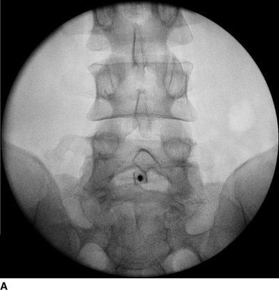
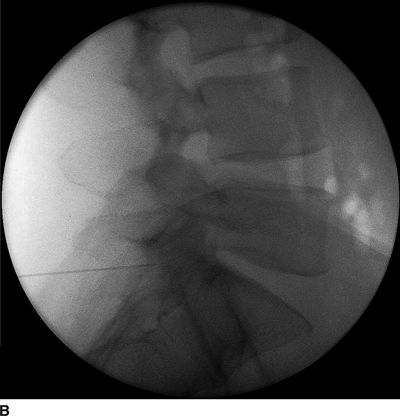
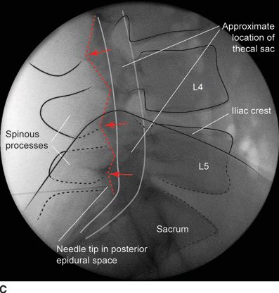
FIGURE 30-4. Radiographic identification of the lumbar epidural space. A: Anterior-posterior radiograph of the lumbar spine during interlaminar lumbar epidural injection. A 20-gauge Tuohy needle is in position between the L5 and S1 laminae with the hub projected directly over the needle tip. B: Lateral radiograph of the lumbar spine during interlaminar lumbar epidural injection. A Tuohy needle is in place in the L5/S1 interspace extending to the posterior epidural space. Clarity of lateral radiographs of the lumbar spine is often hindered by the overlying iliac crests. C: Labeled image. During lumbar interlaminar epidural injection, the needle can be safely advanced using the lateral radiograph to guide depth. The posterior-most extent of the ligamentum flavum lies just anterior to the junction of the spinous process with the laminae (red arrows). The needle can be safely advanced to this depth before starting the LOR technique during the last few millimeters of advancement through the ligamentum flavum to precisely identify the epidural space. The junction of the spinous process with the lamina can be easily identified in the lateral radiograph by following the inferior margin of the spinous processes anteriorly until the junction with the lamina is seen as a line that extends in an inferior and anterior direction (dashed line). The approximate location of the thecal sac is shown (gray lines indicate the approximate location of the anterior and posterior aspects of the dura mater).
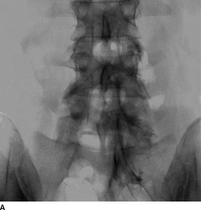
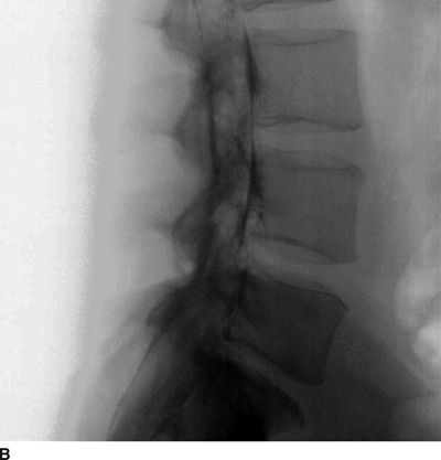
FIGURE 30-5. Lumbar epidurography. A: Anterior-posterior epidurogram of the lumbosacral spine. When larger volumes of injectate are used (in this image, 10 mL of contrast-containing solution), the injectate spreads extensively within the anterior and posterior epidural space and exits the intervertebral foramina, surrounding the exiting nerve roots. However, in the presence of significant obstruction to flow, as in this patient with a right L4/L5 disc herniation and compression of the exiting right L4 nerve root, the injectate often follows the path of least resistance, exiting the foramina on the side opposite from the disc herniation. B: Lateral epidurogram of the lumbosacral spine. When larger volumes of injectate are used (in this image, 10 mL of contrast-containing solution), the injectate spreads extensively within the anterior and posterior epidural space and has a characteristic double line or railroad track appearance. (Adapted from Rathmell JP, Torian D, Song T. Lumbar epidurography. Reg Anesth Pain Med 2000;25:542, with permission.)
Intravascular injection can lead to local anesthetic toxicity or catastrophic neural injuries to the brain or spinal cord, when particulate steroid is in use. With proper use of radiographic guidance, intravascular needle location can be easily detected before local anesthetic or steroid is injected; thus, use of radiographic guidance may well improve safety. The incidence of intravascular needle location exceeds 20% during cervical transforaminal injection,10,11 and it is unclear what proportion of these injections are intravenous versus intra-arterial.12 Use of digital subtraction technology appears to further increase the likelihood of detection of intravascular injection.13 While intravascular injection is common during cervical transforaminal injection, the incidence during other pain treatment techniques is unclear. Nonetheless, the proximity of the vertebral artery during stellate ganglion block and the aorta during celiac plexus block make intraarterial injection a distinct possibility, and means to detect intra-arterial needle location before injection of local anesthetic or steroid must be a routine part of performing these techniques.
It is impossible to gain any real estimate of the incidence of injuries occurring during the course of pain treatment, as there is no direct reporting mechanism. The ASA Closed Claims study gives us just a small glimpse of the injuries that can occur, with or without image guidance. Nonetheless, the incidence of these injuries appears to be exceedingly low, likely less than 1 in 10,000 injections and perhaps significantly lower; while it is difficult to estimate this risk with accuracy, in 2006, nearly 800,000 Medicare patients in the United States14 received epidural injections and catastrophic neural injuries on record number <100 in total. What is quite clear from published studies is that the use of common injections for pain treatment has risen exponentially in the United States during the last decade14 and that use of fluoroscopy to guide needle placement during these treatments is the rule rather than the exception. We are in desperate need of large-scale studies that examine the frequency of use of these treatments and their safety and effectiveness to guide practitioners in making rational decisions about using these techniques.
 MECHANISM OF CAUSATION
Injuries associated with image-guided pain treatment fall into several broad categories. Bleeding and infectious complications are rare, but can be devastating, including epidural hematoma and epidural abscess—these complications have been discussed in detail in Chapters 4 and 5, respectively. Use of image guidance is unlikely to impact the incidence of either of these complications, but diagnostic imaging is integral to prompt diagnosis and treatment. In contrast, image guidance does play a critical role in avoiding direct trauma to neural structures as well as preventing unintended intravascular or intrathecal injection.
Direct Trauma to Neural Structures
Direct trauma to neural structures, including the spinal nerves at the level of the intervertebral foramina, the cauda equina, or the spinal cord itself, have all been associated with specific injections used in pain treatment. Specifically, direct needle contact with spinal nerves during transforaminal injection is not uncommon. This typically causes a transient paresthesia, which resolves promptly with redirection of the needle, but results in persistent pain in some individuals. Likewise, transforaminal injection is often carried out to treat radicular pain associated with foraminal stenosis and or nerve compression associated with disc herniation. In these conditions, there is little space around the spinal nerve to accommodate the injected fluid, and paresthesia caused by the injected fluid causing some element of worsened nerve compression may occur. The spinal cord lies directly in front of the advancing needle during both transforaminal and interlaminar epidural injections carried out at the cervical level, and direct needle trauma to the cord can occur.9 Patients with severe stenosis of the central spinal canal may be at particular risk for spinal cord injury, especially when using an interlaminar technique.4
Vascular Compromise
Evidence for vascular compromise has arisen in two areas: paraplegia following neurolytic celiac plexus block15,16 and catastrophic neural injuries associated with injection of particulate steroid, particularly during cervical transforaminal injection.17 Paraplegia following neurolytic celiac plexus block has been discussed in detail in Chapter 23. Briefly, celiac plexus block is commonly carried out at the T12/L1 vertebral level, and the injectate is placed over the anterolateral aspect of the vertebral bodies or around the anterolateral aspect of the aorta. The artery of Adamkiewicz, the largest spinal segmental artery, arises from the posterolateral aspect of the aorta, most often on the left between the T10 and L2 vertebral levels, in the precise vicinity where the injectate is placed for celiac plexus block. This artery is critical to providing adequate blood supply to the anterolateral spinal cord at the low thoracic level, and compromise of this vessel can lead to spinal cord ischemia and/or infarction similar to that seen in patients undergoing surgical repair of the thoracic spinal cord for aneurysm or dissection. The injection of neurolytic solution in this region has been hypothesized to lead to spasm of this critical reinforcing artery, and there is at least one case of transient paraplegia.15 More often, the neurologic insult is permanent. While the mechanism may by arterial spasm and resultant ischemia, as our understanding of the spinal cord injury that ensues after intra-arterial injection of particulate steroid into the same vessel, it seems more plausible that the spinal cord injury is the direct result of intra-arterial injection of the neurolytic solution.
Catastrophic neural injury following intra-arterial injection of particulate steroid has been well described in association with transforaminal injections,17 stellate ganglion block,9 and cervical facet injections.18 Several mechanisms of injury have been postulated to lead to injury during these injections, including arterial spasm or dissection, but no evidence to support these alternate mechanisms has emerged. The likely mechanism is direct intra-arterial injection of minute steroid particles in suspension that occlude the end-arteriolar circulation of the vessel injected, leading to ischemia and infarction. During transforaminal injection, injection into the spinal medullary arteries can lead to spinal cord infarction, and injection into the vertebral artery can lead to occlusion of the end arterioles in the posterior cerebral circulation, resulting in cortical blindness, cerebellar infarction, and death from the resultant intracranial hypertension. Direct injection in to the vertebral artery can also occur with stellate ganglion block or high-cervical facet injections. This mechanism of injury is strongly supported by studies in experimental animals19,20 and in case reports detailing the resultant injuries. 18 In an elegant study using anesthetized swine, injection of particulate steroid into the vertebral artery resulted in massive posterior circulation stokes on MRI and persistent coma without any spontaneous respiratory effort in these animals19; in contrast, intra-arterial injection of the nonparticulate steroid dexamethasone causes no apparent injury to the brain. In a detailed case report of a man receiving a C1/C2 intra-articular facet injection with particulate steroid, intraarterial injection into the adjacent vertebral artery resulted in a massive, fatal posterior circulation stroke18 (Fig. 30-6). These publications strongly support the mechanism of injury of particulate steroid causing end-arteriolar occlusion; the alternate hypotheses of arterial spasm or dissection have no evidence to support them to date.
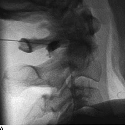
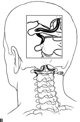
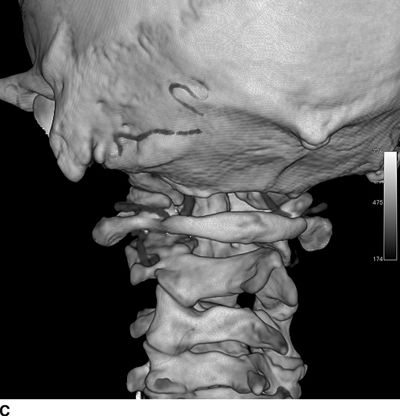
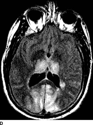
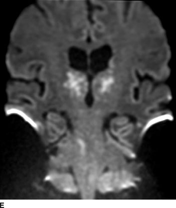
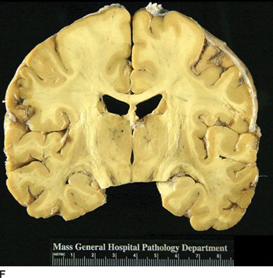
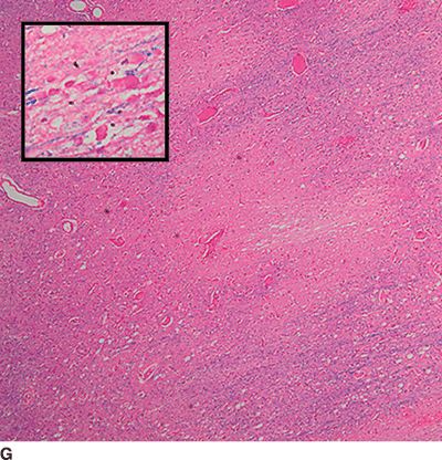
FIGURE 30-6. Massive posterior circulation stroke resulting from inadvertent injection of particulate steroid into the left vertebral artery during C1/2 intra-articular facet injection. This patient became comatose immediately after the intra-articular cervical facet steroid injection. A: Lateral x-ray shows needle posterior to the C1/2 joint, with radiographic contrast over the posterior portion of the joint. B: Schematic illustration, with inset highlighting the anatomic area of interest, demonstrates proximity of superior cervical portion of the vertebral artery to the injection site. C: Reformatted CT angiography of the left vertebral artery (posterior view), performed 5 hours after the cervical injection, does not reveal evidence of arterial dissection, vasospasm, or occlusion. D: Axial T2 fluid attenuated inversion recovery sequence MRI reveals signal hyperintensity within the posterior circulation territory. E: Coronal diffusion-weighted imaging sequence through the thalami demonstrates bithalamic diffusion restriction as well as right pontine. F: Fixed brain demonstrates gross evidence of bithalamic necrosis and microhemorrhages. G: Luxol fast blue with hematoxylin and eosin staining of thalamic section demonstrates small irregular discrete areas of acute infarction. G, Inset: Axonal spheroids are present in the surrounding thalamus adjacent to the lesions, consistent with ischemic injury. The combination of small, distinct regions of infarction with axonal spheroids confirms that the ischemic lesions occurred due to occlusion of distal vascular beds, consistent with the hypothesis of microembolization. (Adapted from Edlow BL, Wainger BJ, Frosch MP, et al. Posterior circulation stroke after C1-C2 intraarticular facet steroid injection: evidence for diffuse microvascular injury. Anesthesiology 2010;112:1532–1535, with permission.)


