Chapter 14 Oxygen Delivery Systems, Inhalation Therapy, and Respiratory Therapy
II Oxygen Therapy
A Indications
O2 is one of the most common therapeutic substances used in the practice of critical care medicine. O2 therapy may improve outcomes of patients undergoing surgery. Use of O2 concentrations greater than 50% FIO2 has reduced the incidence of wound infections in patients undergoing colorectal or spinal surgery.1–4 This section reviews some of the indications, goals, and modes of O2 therapy in the adult patient.
Treatment or prevention of hypoxemia is the most common indication for O2 therapy, and the final goal of effective treatment is avoidance or resolution of tissue hypoxia. Tissue hypoxia exists when delivery of O2 is inadequate to meet the metabolic demands of the tissues. O2 content (Box 14-1) depends on the arterial partial pressure of O2 (PaO2), the hemoglobin concentration of arterial blood, and the saturation of hemoglobin with O2. O2 delivery (DO2) is calculated by multiplying cardiac output (liters per minute) by the arterial O2 content. DO2 is measured in milliliters of O2 per minute, and for a 70-kg, healthy patient, it is approximately 1000 mL/min (Box 14-2).
Box 14-2 Calculation of Oxygen Delivery
CaO2= arterial O2 content per 100 mL of blood mL/dL. This value is approximately 20 mL/dL in the normal adult with a hemoglobin of 15 g/dL.
CO= cardiac output (L/min). This value is approximately 5 L/min in the healthy, 70-kg adult.
DO2= O2 delivery (mL/min). This value is approximately 1000 mL/min in the healthy, 70-kg adult.
B Oxygen Delivery Systems
With the exception of anesthetic breathing circuits, virtually all O2 delivery systems are nonrebreathing. In nonrebreathing circuits, the inspiratory gas is not made up in any part by the exhaled tidal volume (VT), and the only CO2 inhaled is that in any entrained room air. To avoid rebreathing, exhaled gases must be sequestered by one-way valves, and inspired gases must be presented in sufficient volume and flow to satisfy the high peak flow rates and minute ventilation demonstrated in critically ill patients. Inspiratory entrainment of room air or the use of inspiratory reservoirs (including the anatomic dead space of the nasopharynx, oropharynx, and non–gas-exchanging portion of the bronchial tree) and one-way valves typifies nonrebreathing systems and defines them as two groups.5–7 Low-flow systems depend on inspiration of room air to meet inspiratory flow and volume demands. High-flow systems attempt to provide the entire inspiratory demand. High-flow systems use reservoirs or very high flow rates to meet the large peak inspiratory flow demands and the exaggerated minute volumes found in many critically ill patients.
1 Low-Flow Oxygen Systems
A low-flow, variable-performance system depends on room air entrainment to meet the patient’s peak inspiratory and minute ventilatory demands that are not met by the inspiratory gas flow or O2 reservoir alone. Low-flow devices include the nasal cannula, simple face mask, partial rebreathing mask, nonrebreathing mask, and tracheostomy collar. Low-flow systems are characterized by the ability to deliver high and low values of FIO2. The FIO2 becomes unpredictable and inconsistent when these devices are used for patients with abnormal or changing ventilatory patterns.8 Low-flow systems produce FIO2 values of 21% to 80%. The FIO2 may vary with the size of the O2 reservoir, O2 flow, and the patient’s ventilatory pattern (e.g., VT, peak inspiratory flow, respiratory rate, minute ventilation). With a normal ventilation pattern, these devices can deliver a relatively predictable and consistent FIO2 level.
The example for estimation of FIO2 from a low-flow system is based on the standard normal patient and ventilatory pattern. Several assumptions are used for the FIO2 calculation. The anatomic reservoir for a nasal cannula consists of nose, nasopharynx, and oropharynx, and it is about one third of the entire normal anatomic dead space (including trachea). For example, 150 mL ÷ 3 = 50 mL; assume a nasal cannula O2 flow rate of 6 L/min (100 mL/sec), VT of 500 mL, respiratory rate of 20 breaths/min, inspiratory (I) time of 1 second, and expiratory (E) time of 2 seconds. If the terminal 0.5 second of the 2-second expiratory time has negligible gas flow, the anatomic reservoir (50 mL) completely fills with 100% O2, assuming an O2 flow rate of 100 mL/sec. Using the preceding normal variables, the FIO2 is calculated for a patient with a 500 mL and a 250 mL VT (Tables 14-1 and 14-2).
TABLE 14-1 Example 1: VT Is Decreased to 500 mL
| Cannula | 6 L/min | VT, 500 mL |
| Mechanical reservoir | None | I/E ratio = 1 : 2 |
| Anatomic reservoir | 50 mL | Rate = 20 breaths/min |
| 100% O2 provided/sec | 100 mL | Inspiratory time = 1 sec |
| Volume inspired O2 | ||
| Anatomic reservoir | 50 mL | |
| Flow/sec | 100 mL | |
| Inspired room air (0.20 × 350 mL) | 70 mL | |
| O2 inspired | 220 mL | |
 |
FIO2, Fraction of inspired oxygen; I/E ratio, inspiration/expiration ratio; VT, tidal volume.
TABLE 14-2 Example 2: If VT Is Decreased to 250 mL
| Volume inspired O2 | |
| Anatomic reservoir | 50 mL |
| Flow/sec | 100 mL |
| Inspired room air (0.20 × 100 mL) | 20 mL |
| O2 inspired | 170 mL |
 |
FIO2, Fraction of inspired oxygen; VT, tidal volume.
Low-flow O2 devices are the most commonly employed O2 delivery systems because of simplicity, ease of use, familiarity, economics, availability, and acceptance by patients. In most clinical situations (see “High-Flow Oxygen Systems” and “High-Flow Devices”), these systems should be initially employed.
2 High-Flow Oxygen Systems
High-flow, fixed-performance systems are nonrebreathing systems that provide the entire inspiratory atmosphere needed to meet the peak inspiratory flow and minute ventilatory demands of the patient. The flow rate and reservoir are essential to meet the patient’s peak inspiratory flow. Flows of 30 to 40 L/min (or three to four times the measured minute volume) are often necessary. High-flow devices include aerosol masks and T-pieces that are powered by air-entrainment nebulizers or air-O2 blenders and Venturi masks (see “Oxygen Delivery Devices”). Regardless of the patient’s respiratory pattern, high-flow systems are expected to deliver predictable, consistent, and measurable high and low FIO2 values. High-flow systems also can control the humidity and temperature of the delivered gases. The primary limitations of these systems are cost, bulkiness, and patients’ tolerance.
There are two primary indications for high-flow O2 devices:
1. Patients who require a consistent, predictable, minimal FIO2 to reverse hypoxemia but prevent respiratory compromise due to excessive O2 delivery (see “Complications”)
2. The patient with increased minute ventilation and abnormal respiratory pattern who needs predictable and consistent high FIO2 values
C Oxygen Delivery Devices
1 Low-Flow Devices
a Nasal Cannulas
Because of their simplicity and the ease with which patients tolerate them, nasal cannulas are the most frequently used O2 delivery devices. The nasal cannula consists of two prongs, with one inserted into each naris, that deliver 100% O2. To be effective, the nasal passages must be patent, but the patient need not breathe through the nose. The flow rate settings range from 0.25 to 6 L/min. The nasopharynx serves as the O2 reservoir (Fig. 14-1). Gases should be humidified to prevent mucosal drying if the O2 flow exceeds 4 L/min. For each 1 L/min increase in flow, the FIO2 is assumed to increase by 4% (Table 14-3).
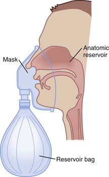
Figure 14-1 The three reservoirs of low-flow oxygen therapy.
(From Vender JS, Clemency MV: O2 delivery systems, inhalation therapy, and respiratory care. In Benumof JL, editor: Clinical procedures in anesthesia and intensive care, Philadelphia, 1992, JB Lippincott, pp 63–87.)
TABLE 14-3 Approximate FIO2 Delivered by Nasal Cannula
| Flow Rate (L/min) | Approximate FIO2* |
|---|---|
| 1 | 0.24 |
| 2 | 0.28 |
| 3 | 0.32 |
| 4 | 0.36 |
| 5 | 0.40 |
| 6 | 0.44 |
FIO2, Fraction of inspired oxygen.
* Based on normal ventilatory patterns.
Avoidance of undue cutaneous pressure is essential. Gauze may be needed to pad pressure points around the cheeks and ears during prolonged use. The flowmeter should be adjusted to the prescribed liter flow to attain the desired FIO2 (see Table 14-3).
Although nasal cannulas are simple and safe, several potential hazards and complications exist. O2 supports combustion, and any type of O2 therapy is a fire hazard. Nasal trauma from prolonged use of or pressure from the nasal prongs can cause tissue damage. With poorly humidified, high gas flows, the airway mucosal surface can become dehydrated. This mucosal dehydration can result in mucosal irritation, epistaxis, laryngitis, ear tenderness, substernal chest pain, and bronchospasm.5,7,9 Because this is a low-flow system, the FIO2 can be inaccurate and inconsistent, leading to the potential for underoxygenation or overoxygenation. Overoxygenation may induce respiratory distress in patients with severe COPD by reversing protective hypoxic pulmonary vasoconstriction, depressing ventilation, and minimizing the Haldane effect (see “Complications”). Underoxygenation potentiates any problems associated with hypoxemia.
b Simple Face Mask
To provide a higher FIO2 value than that provided by nasal cannula with low-flow systems, the size of the O2 reservoir must increase (see Fig. 14-1). A simple face mask consists of a mask with two side ports. The mask serves as an additional O2 reservoir of 100 to 200 mL. The side ports allow room air entrainment and exit for exhaled gases. The mask has no valves. An FIO2 of 0.40 to 0.60 can be achieved predictably when patients exhibit normal respiratory patterns. Gas flows greater than 8 L/min do not significantly increase the FIO2 above 0.60 because the O2 reservoir is filled. A minimum flow of 5 L/min is necessary to prevent CO2 accumulation and rebreathing. The delivered O2 value depends on the ventilatory pattern of the patient, similar to the situation with nasal cannulas.
The equipment needed is identical to that used for nasal cannula O2 administration. The only difference is the use of a face mask. The predicted FIO2 can be estimated from the O2 flow rate (Table 14-4). Appropriate mask application is needed with all masks to maximize the FIO2 and the patient’s comfort. The mask should be positioned over the nasal bridge and the face, restricting O2 escape into the patient’s eye, which can cause ocular drying and irritation. If FIO2 values above 0.60 are required, a partial rebreathing mask, nonrebreathing mask, or high-flow system should be employed. All O2 devices that deliver higher values of FIO2 increase the potential of O2 toxicity (see “Complications”).
TABLE 14-4 Approximate FIO2 Delivered by Simple Face Mask
| Flow Rate (L/min) | FIO2* |
|---|---|
| 5–6 | 0.4 |
| 6–7 | 0.5 |
| 7–8 | 0.6 |
FIO2, Fraction of inspired oxygen.
c Partial Rebreathing Mask
To deliver an FIO2 level of more than 60% with a low-flow system, the O2 reservoir system must be increased (see Fig. 14-1).7 A partial rebreathing mask adds a reservoir bag with a capacity of 600 to 1000 mL. Side ports allow entrainment of room air and the exit of exhaled gases. The distinctive feature of this mask is that the first 33% of the patient’s exhaled volume fills the reservoir bag. This volume is derived from the anatomic dead space and contains little CO2. During inspiration, the bag should not completely collapse. A deflated reservoir bag results in a decreased FIO2 because of entrained room air. With the next breath, the first exhaled gas (which is in the reservoir bag) and fresh gas are inhaled—accounting for the name partial rebreather. Fresh gas flows should be 8 L/min or greater, and the reservoir bag must remain inflated during the entire ventilatory cycle to ensure the highest FIO2 and adequate CO2 evacuation. An FIO2 of 0.60 to 0.80 or more can be delivered with this device if the mask is applied appropriately and the ventilatory pattern is normal (Table 14-5). This mask’s rebreathing capacity allows O2 conservation and may be useful during transportation, when O2 supply may be limited. Complications with partial rebreathing O2 delivery systems are similar to those with other mask devices with low-flow systems.
TABLE 14-5 Approximate FIO2 Delivered by Mask with Reservoir Bag
| Flow Rate (L/min) | FIO2* |
|---|---|
| 6 | 0.6 |
| 7 | 0.7 |
| 8 | 0.8 |
| 9 | 0.8+ |
| 10 | 0.8+ |
FIO2, Fraction of inspired oxygen.
d Nonrebreathing Mask
A nonrebreathing mask (Fig. 14-2) is similar to a partial rebreathing mask but adds three unidirectional valves. One valve is located on each side of the mask to permit the venting of exhaled gases and to prevent room air entrainment. The third unidirectional valve is situated between the mask and the reservoir bag and prevents exhaled gases from entering the bag.
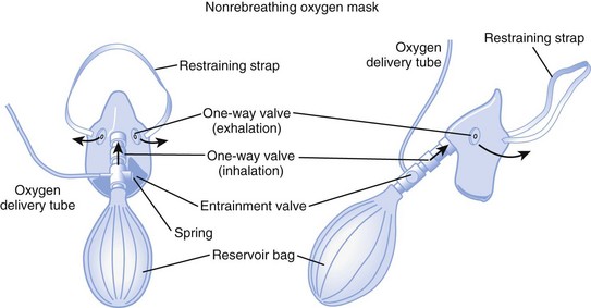
Figure 14-2 A nonrebreathing oxygen mask. In addition to the exhalation valve, the mask has a one-way inhalation valve.
(From Vender JS, Clemency MV: Oxygen delivery systems, inhalation therapy, and respiratory care. In Benumof JL, editor: Clinical procedures in anesthesia and intensive care, Philadelphia, 1992, JB Lippincott.)
2 High-Flow Devices
a Venturi Masks
High-flow systems have flow rates and reservoirs large enough to provide the total inspired gases reliably. Most high-flow systems use gas entrainment at some point in the circuit to provide the flow and FIO2 needs. Venturi masks entrain air by the Bernoulli principle and constant pressure-jet mixing.10 This physical phenomenon is based on a rapid velocity of gas (e.g., O2) moving through a restricted orifice. This action produces viscous shearing forces that create a decreased pressure gradient (subatmospheric) downstream relative to the surrounding gases. The pressure gradient causes room air to be entrained until the pressures are equalized. Figure 14-3 illustrates the Venturi principle.
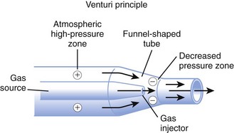
Figure 14-3 Application of the Venturi principle.
(From Vender JS, Clemency MV: Oxygen delivery systems, inhalation therapy, and respiratory care. In Benumof JL, editor: Clinical procedures in anesthesia and intensive care, Philadelphia, 1992, JB Lippincott.)
1. A fixed FIO2 model, which requires specific inspiratory attachments that are color coded and have labeled jets that produce a known FIO2 with a given flow
2. A variable FIO2 model (Fig. 14-4), which has a graded adjustment of the air entrainment port that can be set to allow variation in delivered FIO2
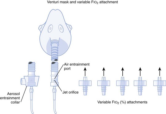
Figure 14-4 Graded air entrainment by the Ventimask provides specific FIO2 levels through the jet orifices.
(From Vender JS, Clemency MV: Oxygen delivery systems, inhalation therapy, and respiratory care. In Benumof JL, editor: Clinical procedures in anesthesia and intensive care, Philadelphia, 1992, JB Lippincott.)
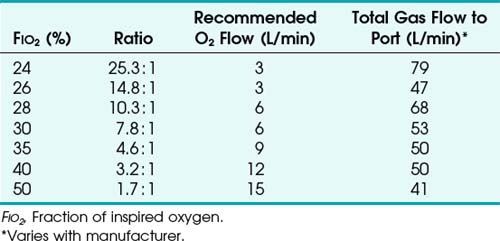
To use any air entrainment device properly to control the FIO2, the standard air-O2 entrainment ratios and minimum recommended flows for a given FIO2 level must be used (Table 14-6). The minimum total flow requirement should result from entrained room air added to the fresh O2 flow and equal three to four times the minute ventilation. This minimal flow is required to meet the patient’s peak inspiratory flow demands. As the desired FIO2 increases, the air-O2 entrainment ratio decreases with a net reduction in total gas flow. The higher the desired FIO2, the greater the probability of the patient’s needs exceeding the total flow capabilities of the device.
Venturi masks are often useful when treating patients with COPD who may develop worsening respiratory distress and dead space ventilation with supplemental increases in O2 fraction.11,12 The Venturi mask’s ability to deliver a high flow with no particulate H2O makes it beneficial in treating asthmatics, in whom bronchospasm may be precipitated or exacerbated by aerosolized H2O administration.
b High-Flow Nasal Cannulas
High-flow nasal cannulas have been developed that can provide humidified gas flows up to 50 L/min while achieving 72% to 100% FIO2.13 Consistent delivery of humidification is also maintained at 72% to 99.9% relative humidity through the use of specialized nasal cannulas,14 larger tubing, high-flow humidifiers, and O2 blenders. These high-flow nasal cannulas can generate moderate levels of continuous positive airway pressure (CPAP) in nasal- and mouth-breathing patients.15 It does not require a face mask, unlike most other high-flow systems, and this affords patients the opportunity to verbally communicate and eat in a normal manner.
c Aerosol Masks and T-Pieces with Nebulizers or Air-Oxygen Blenders
Air entrainment nebulizers can deliver FIO2 of 0.35 to 1.00 and produce an aerosol. The maximum gas flow through the nebulizer is 14 to 16 L/min. As with the Venturi masks, less room air is entrained with higher FIO2 values. As a result, total flow at high FIO2 values is decreased. To meet ventilatory demands, two nebulizers may feed a single mask to increase the total flow, and a short length of corrugated tubing may be added to the aerosol mask side ports to increase the reservoir capacity (Fig. 14-5). If the aerosol mist exiting the mask side ports disappears during inspiration, room air is probably being entrained, and flow should be increased.
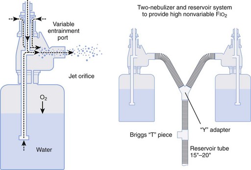
Figure 14-5 Single-unit and double (tandem)-unit mechanical aerosol systems.
(From Vender JS, Clemency MV: Oxygen delivery systems, inhalation therapy, and respiratory care. In Benumof JL, editor: Clinical procedures in anesthesia and intensive care, Philadelphia, 1992, JB Lippincott.)
D Humidifiers
Room air that has a relative humidity of 50% at 21° C has a relative humidity of 21% at 37° C. Under normal conditions, the lungs contribute about 250 mL of H2O per day to maximally saturate inspired air.7
A humidifier increases the heated or unheated water vapor in a gas. This can be accomplished by passing gas over heated water (heated passover humidifier); by fractionating gas into tiny bubbles as gas passes through water (bubble diffusion or jet humidifiers); by allowing gas to pass through a chamber that contains a heated, water-saturated wick (heated wick humidifier); and by vaporizing water and selectively allowing the vapor to mix with the inspired gases (vapor-phase humidifier). Other variations of humidification systems exist but are beyond the scope of this chapter.16
Bubble humidifiers can be used with nasal cannulas, simple face masks, partial and nonrebreathing masks, and air-O2 blenders. They increase the relative humidity of gas from 0% to 70% at 25° C, which is approximately equal to 34% at 37° C.17,18 Large-volume bubble-through humidifiers are available for use with ventilator circuits or high-gas-flow delivery systems.
Heat and moisture exchangers (HMEs) are simple, small humidifier systems designed to be attached to an artificial airway. The HMEs are often referred to as an artificial nose. The efficiency of these devices is quite variable, depending on the HME design, VT, and atmospheric conditions. HMEs are typically used for short-term ventilatory support and for humidification during anesthesia. Several contraindications include use in neonatal and small pediatric patients; copious secretions; significant spontaneous breathing, in which the patient’s VT exceeds the HME specifications; and large-volume losses through a bronchopleural fistula or leakage around the ETT.16
A nebulizer increases the water content of the inspired gas by generating aerosols (small droplets of particulate water) that become incorporated into the delivered gas stream and then evaporate into the inspired gas as it is warmed in the respiratory tract. There are two basic kinds of nebulizers: pneumatic and electric. Pneumatic nebulizers operate from a pressured gas source and are jet or hydrodynamic. Electric nebulizers are powered by an electrical source and are referred to as ultrasonic. There are several varieties of both types of nebulizers, and they depend more on design differences than on the power source. A more in-depth discussion of nebulizers is available elsewhere.7,9 The resultant humidity ranges from 50% to 100% at 37° C, depending on the device used. If heated, the relative humidity of the gas can exceed 100% at 37° C. Air entrainment nebulizers are used in conjunction with aerosol masks and T-pieces.
Aerosol therapy can be used for three general purposes. First, aerosol therapy increases the particulate and molecular water content of the inspired gases. The aerosol increases the water content of desiccated and retained secretions, enhancing bronchial hygiene. This does not alleviate the need for systemic hydration. Second, delivery of medications is a primary indication for aerosol therapy. For example, β2-agonists, corticosteroids, anticholinergics, and antiviral-antibacterial agents (see “Inhalation Therapy”) may be delivered to patients’ airways by aerosol therapy. Third, aerosol therapy can be employed for sputum induction. The success of aerosol therapy depends on appropriate application and proper technique of administration.
The aerosol generated by the nebulizer can precipitate bronchospasm of hyperactive airways.5,7 Prophylactic bronchodilator therapy should be employed before or during the aerosol treatment. Fluid accumulation and overload have been reported. These problems are more common in treating pediatric patients and with continuous ultrasonic rather than intermittent or jet therapy. Dry secretions are hydrophilic and can swell because of the absorbed water content. If secretions swell, they can obstruct airways. Mobilization of secretions limits this problem. Aerosol therapy for drug delivery has been reported to precipitate the same side effects as systemic drug delivery. Therapeutic aerosols have been implicated in nosocomial infections.19 Cross-contamination between patients must be avoided.
Stay updated, free articles. Join our Telegram channel

Full access? Get Clinical Tree


 ) and diffusion defect.
 ) is essentially an uncoupling of alveolar blood supply and ventilation. In an area of low
  , hypoxemia results when mixed venous blood flowing past the alveolar-capillary membrane (ACM) takes away O2 molecules faster than ventilation to the alveolus can replace them. The resultant partial pressure of O2 in the alveolus (P
 = 0. Anatomic shunt occurs when blood flows from the right side of the heart to the left side without traversing the pulmonary capillaries. A small percentage of physiologic shunt results from bronchial and thebesian circulation. True intrapulmonary shunts cause hypoxemia that is poorly responsive to O2 therapy. Therapy for “oxygen-refractory” hypoxemia is aimed at reducing the shunt. Different levels of shunting, such as low-ventilation areas, often cause blood to flow through capillaries adjacent to alveoli that do not participate in ventilation. Atelectasis is a common cause of this type of shunt. Respiratory therapy, such as tracheobronchial toilet, to remove mucous plugging of a lobar bronchus or adjusting an endotracheal tube (ETT) that has advanced into a main stem bronchus, may be effective at reversing causes of relative shunt. Positive airway pressure therapy can reduce intrapulmonary shunting in certain disease states associated with a diffuse reduction in functional residual capacity.
 ratio, a portion of ventilation does not participate in gas exchange. Dead space ventilation occurs when the perfusion becomes zero, and the
  ratio approaches infinity. Anatomic dead space is an area of the lungs that does not participate in gas exchange, such as the larger airways. Physiologic dead space is the total dead space that contributes to elevated
  ratio. Dead space ventilation does not contribute significantly to hypoxemia unless perfusion is significantly disrupted, as occurs in a pulmonary embolus.
 mismatch share a common phenomenon, which is exaggerated by a decreased mixed venous hemoglobin saturation (low
  ). Because hemoglobin saturation is the major determinant of O2 content in blood, a low
  leads to a low venous O2 content (
 ). Low
  causes hypoxemia by worsening the hypoxemic effect of any existing shunt or areas of low
  by presenting more desaturated blood to the left atrium. Decreased
  arises from low O2 delivery (e.g., low cardiac output, anemia, hypoxemia) or increased O2 consumption (e.g., high fever, increased minute ventilation and work of breathing).