CHAPTER 6 Peripheral nerve block materials
Nerve stimulators
In 1911, Stoffel demonstrated how a galvanic current could be applied to identify nerve fibers.1 A year later, Perthes described how the use of electrical stimulation could improve the safety of neural block in the practice of anesthesia.2
Nerve stimulation is a popular technique for the location and identification of nerve fibers, particularly in Europe.3 It was introduced into contemporary practice in 1973 by Montgomery and Raj against considerable opposition, particularly in the USA, where many practitioners advocated the dictum ‘no paresthesia, no anesthesia’.4,5 Nerve stimulation, through the intentional avoidance of direct contact with the nerve fiber, aims to reduce the risk of neurologic complications. However, the relations between stimulating current, motor and sensory responses, success rates, and needle–nerve distances are far from clear in the clinical setting.6–8 The nerve stimulation method produces peripheral nerve injury in up to three cases in 10 000.9 In contrast, the transarterial approach to brachial plexus anesthesia produces nerve lesions in 0.8% of cases and the paresthesia approach in 2.8%.10,11 The following is a discussion on the theoretical as well as practical aspects of nerve stimulation and the equipment commonly used to locate nerves. The reader should remain cognizant of the fact that no definitive study outlining the exact nature of the relationship between the stimulating current and the observed responses in clinical practice exists to date.
Electrophysiology
The electrochemical nature of nerve fiber conduction renders it amenable to electrical stimulation. The strength–duration curve demonstrates the relation between the intensity and duration of current in peripheral nerve stimulation (Fig. 6.1).
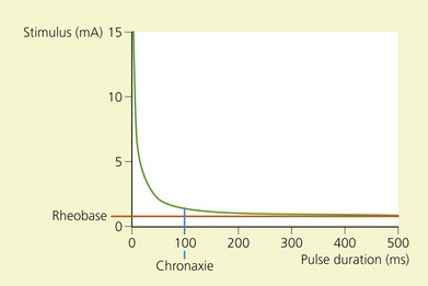
The chronaxie of a motor nerve is less than that of a sensory nerve. In the clinical setting, therefore, a motor response may be elicited without stimulating pain fibers if the duration of impulse is short. Sensory nerves may also be identified using a nerve stimulator if the pulse duration is greater than 400 µs (Table 6.1).
Table 6.1 Chronaxies of mammalian peripheral nerves
| Nerve fiber type | Chronaxie | |
|---|---|---|
| Cat sural nerve | Aα | 50–100 µs13 |
| Aδ | 170 µs14 | |
| Cat saphenous nerve | C | 400 µs15 |
(From Pither C, Prithvi R, Ford D. The use of peripheral nerve stimulators for regional anesthesia. A review of experimental characteristics, techniques and clinical applications. Reg Anesth 1985; 10; 49–58, with permission from the American Society of Regional Anesthesia and Pain Medicine.)
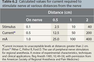
governs the relation between the stimulus intensity and the distance from the nerve. E is the current required, K a constant, Q the minimal current, and r the distance. The significance lies in the squaring of the distance. While one may thus approach the nerve through the progressive diminution of current, at distances greater than 0.5 cm from the nerve large currents are required; at greater than 2 cm, currents of up to 50 mA may be generated. These currents produce pain locally and require that appropriate care be taken in patients with intracardiac electrodes (Table 6.2).
Table 6.2 Calculated values for current required to stimulate nerve at various distances from the nerve

In practice, U corresponds to the potential difference between the poles of the nerve stimulator; R corresponds to the internal resistance of the patient and the resistance of the cables. The negative electrode is connected to the needle and the positive to the patient’s skin via a gel electrode. Because the interior of a nerve at rest is negatively charged relative to the exterior, if the poles are reversed hyperpolarization of the nerve occurs; it is then necessary to apply a current of greater intensity to achieve the same motor response. These currents may be uncomfortable for the patient (Fig. 6.2, Table 6.3).
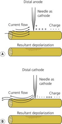
Table 6.3 Polarity of stimulation
| Anodal vs cathodal current required to stimulate peripheral nerve | Reference |
|---|---|
| ∞ 4.57 | BeMent & Ranck, 196916 |
| ∞ 4.3 | Ford et al, 198417 |
(From12 Pither C, Prithvi R, Ford D. The use of peripheral nerve stimulators for regional anesthesia. A review of experimental characteristics, techniques and clinical applications. Reg Anesth 1985; 10; 49–58, with permission from the American Society of Regional Anesthesia and Pain Medicine.)
Characteristics
The characteristics considered desirable in a nerve stimulator are constant current output; digital display; square-shaped, monophasic, negative impulse; variable output control; linear output; clearly marked polarity; short pulse width; variable stimulation frequency of 1 or 2 Hz; high-quality cables and connections; and indicators of power failure, circuit closure, high circuit resistance, and device malfunction.17,18
A digital display of the current intensity delivered is important as one approaches the nerve with very small currents. Knowledge of the precise intensity is vital for accurate nerve location. A final current intensity of 0.5 mA or less is associated with a high success rate in brachial plexus anesthesia.19
To be able to choose between several pulse widths is equally of value. A short pulse width of 50–100 µs is necessary because this corresponds to the chronaxies of mammalian Aα fibers (see Table 6.1). According to Coulomb’s law, the electrical field produced for a current intensity of constant duration is inversely proportional to the square of the distance:

(see previous section, Electrophysiology). Therefore one may bring the needle tip closer to the nerve through the progressive diminution of current intensity. Conversely, as one moves away from the nerve, currents of high intensity are required to stimulate the nerve.


