CHAPTER 26 Pacemaker and Implantable Cardioverter-Defibrillator Emergencies
SECTION I Pacemaker Emergencies
SINCE THE first cardiac pacemaker was implanted in 1958, the field of cardiac pacing has grown rapidly. The number of pacemakers implanted annually increased from 94,755 in 1990 to 267,278 in 2002. From 1990 to 2002, there were 2.25 million pacemakers and 415,780 implantable cardioverter-defibrillators (ICDs) implanted in the United States.1 Thus it is likely that most physicians will have an opportunity to manage patients with these devices, and it is therefore important for physicians to be familiar with the various modes of pacing and with certain aspects of normal and abnormal pacemaker and ICD function. In this section, we discuss the evaluation and management strategies of the more commonly encountered clinical problems in patients with permanent and temporary antibradycardia pacing systems.
Indications for permanent cardiac pacemaker implantation have been published by a joint task force of the American College of Cardiology and the American Heart Association.2,3 The indications have been classified as follows:
Table 26-1 summarizes the indications for permanent cardiac pacing in adults according to the task force guidelines. However, it is recognized that these indications continue to expand, and that clinical situations exist that indicate the need for pacing therapy, yet fall outside the guidelines, in which case documentation of the need is of great importance.
Table 26–1 Guidelines for Implantation of Cardiac Pacemakers in Adults: Class I and II Indications
Abbreviations: AV, atrioventricular; MI, myocardial infarction
Adapted from Gregoratos G, Abrams J, Epstein AE, et al: ACC/AHA/NASPE 2002 guideline for implantation of cardiac pacemakers and antiarrhythmia devices: summary article: report of the American College of Cardiology/American Heart Association task force on practice guidelines (ACC/AHA/NASPE commitee to update the 1998 pacemaker guidelines). Circulation 2002;106:2145-2161.
The indications for temporary cardiac pacing are listed in Table 26-2. These indications are relatively broad, both because of the temporary nature of the clinical problem and the relative ease of implantation and removal of the pacing system. Temporary pacing is indicated in patients awaiting a permanent pacemaker who are symptomatic or who require rate support all or most of the time. Additional indications are symptomatic transient bradyarrhythmias, prophylaxis against bradyarrhythmias, or bradycardia-dependent tachyarrhythmias and hemodynamic dysfunction due to slow rate or atrioventricular (AV) dyssynchrony.
Table 26–2 Indications for Temporary Cardiac Pacing
| Class I |
2. Symptomatic bradycardia (includes sinus bradycardia with hypotension and Type I second-degree AV block with hypotension not responsive to atropine) |
| Class IIa |
| Class IIb |
Abbreviations: AV, atrioventricular; BBB, bundle branch block; R, right; L, left; LAFB, left anterior fascicle block; LPFB, left posterior fascicle block; VT, ventricular tachycardia.
Adapted from Ryan TJ, Anderson JL, Antman EM, et al: J Am Coll Cardiol 1996;28:1367-1368
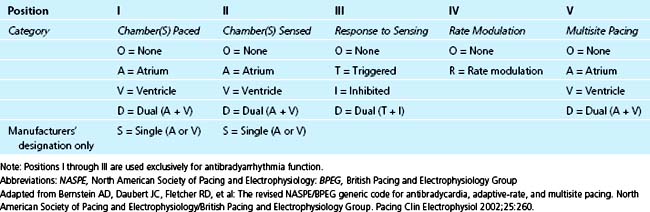
NASPE/BPEG Generic (NBG) Pacemaker Code
In 1974, the Inter-Society Commission on Heart Disease Resources introduced a three-letter pacing-mode code for antibradycardia pacing systems to convey their functions by simple conversational means.4 This mode-code system was expanded to a five-letter one in 1981 to include programmability and antitachycardia functions.5 This code has been adopted and modified by the North American Society of Pacing and Electrophysiology (NASPE) (now the Heart Rhythm Society) Mode Code Committee and the British Pacing and Electrophysiology Group (BPEG), and is designated the NASPE/BPEG generic (NBG) code. Since its inception, the code has undergone multiple revisions; the last in 2002.6 Use of this code by medical and nursing intensive care personnel is recommended, both to facilitate communication and also to accurately describe pacemaker function.
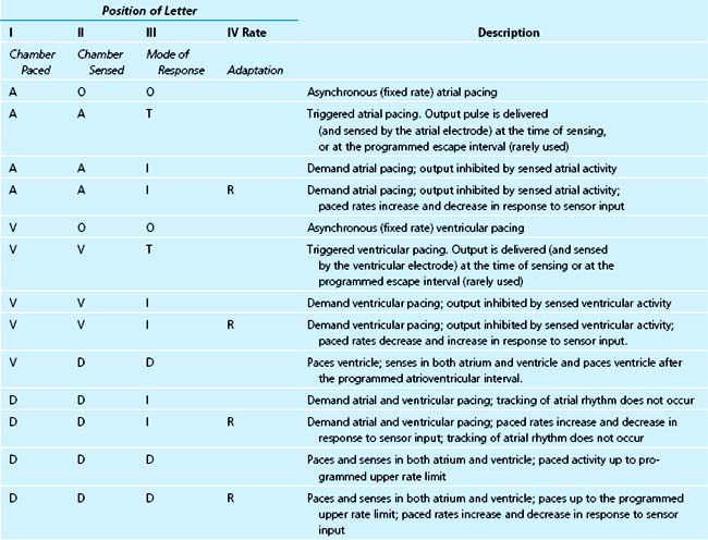
The pacemaker mode code is shown in Table 26-3. The first three letters are always designated. The fourth and fifth letters are omitted if they are “O.” With advances in pacing technology, further revision of the code will almost certainly be necessary. A description of the most commonly used pacing modes is shown in Table 26-4.
Complications of Cardiac Pacing System Implantation
Infection
Infection is an uncommon complication of pacemaker implantation, with the incidence ranging from 0.8% to 5.7%, reported in a review of 21 studies of pacemaker and ICD implantations.7 Routine use of antistaphylococcal antibiotic prophylaxis at the time of implantation or generator change has been shown to have consistent benefit in a meta-analysis of seven randomized controlled trials, representing 2023 patients, in decreasing the rates of short-term pocket infection, skin erosion, or septicemia.8 We recommend routine prophylaxis with antistaphylococcal antibiotics.
Pacemaker pocket infection can occur as early as hours to days after the implantation procedure or as late as several years. Staphylococcus aureus and S. epidermidis are the most common organisms involved; episodes arising within 2 weeks of implantation are more likely to be due to S. aureus, whereas S. epidermidis is the principal organism causing late infections.10,11 Despite the established trend of performing permanent pacemaker implantation in the cardiac catheterization laboratory rather than in the operating room, the incidence of pocket infection has remained the same.12 Clinical manifestations of pocket infection are usually obvious and include fever, chills, purulent drainage, and signs of inflammation at the pocket site. Initial therapy is usually with intravenous antibiotics that provide antistaphylococcal coverage. Management frequently requires removal of the entire pacemaker system.13–15
Endocarditis can occur after pacemaker implantation and has a mortality rate as high as 27%.15 The most frequent pathogens are S. aureus and S. epidermidis.10,11 The diagnosis of device-related endocarditis is suggested by modified Duke criteria; it has been suggested that in the case of devices, pulmonary emboli and generator pocket abnormalities should be used as additional major criteria.15,16
Fever and chills are the most common symptoms. Other signs of endocarditis, such as new murmurs of tricuspid or pulmonic insufficiency or signs of pulmonary hypertension due to septic emboli, should be carefully sought. Vegetations can be best demonstrated by transesophageal echocardiography (TEE), although they are sometimes visualized by transthoracic echocardiography (TTE). TEE has been repeatedly shown to be superior to TTE in the diagnosis of device-related endocarditis, with vegetations on the tricuspid valve or pacing lead visualized by TEE in 90% to 96% of patients, compared with 22% to 43% by TTE.15–20 Complete eradication of the infection usually involves removal of the entire pacing system.13,15,21
Thrombosis and Thromboembolism
Venous thrombosis due to the presence of the pacing lead(s) in the subclavian vein and superior vena cava occurs quite commonly, as assessed by venographic techniques.22 One prospective trial found that six months after pacemaker or defibrillator implantation, 14% of patients developed a new obstructive venous lesion, none of whom were symptomatic.23 Most thromboses are subclinical, and fortunately, major thrombosis causing symptoms and signs of significant venous obstruction (such as the superior vena cava obstruction syndrome) is rare.24 The propagation of thrombus and dislodgement with embolism can cause or contribute to acute or chronic right ventricular inflow or outflow obstruction and can cause acute or recurrent pulmonary embolism.25 Patients with an implanted permanent pacing system having unexplained right-sided heart failure, tachycardia, chest pain, dyspnea, and nonspecific systemic symptoms such as weakness and malaise should be promptly evaluated for these complications, and appropriate studies such as echocardiography and venography should be performed to document their presence. Major and symptomatic venous thrombosis can cause arm and facial edema, pain, absence or diminution of ipsilateral venous pulsations, prominent subcutaneous venous pattern due to collateral circulation, and even exophthalmos. Treatment usually requires intravenous heparinization followed by oral anticoagulation; other treatment modalities include local thrombolysis and balloon angioplasty.26,27
Intracardiac (generally right atrial) thrombosis around the intracardiac portion of the electrode catheter is more dangerous and more difficult to manage. The size of a right atrial thrombus can range from one to several centimeters in diameter.28 The hemodynamic significance of the intracardiac clot depends on its size and location; atrial arrhythmias can occur if the sinoatrial area is involved. Functional tricuspid stenosis or insufficiency can be manifestations of thrombus, similar to those of an atrial myxoma. Intracardiac thrombosis should be considered when refractory right ventricular failure is present; the diagnosis can be confirmed by transthoracic or preferably transesophageal echocardiography.29–31
The true incidence of pulmonary embolism due to transvenous pacing leads is higher when assessed by ventilation perfusion scans than is clinically apparent,32 the latter reported to range from 0.6% to 3.5%.33,34 This discrepancy indicates that most emboli are not of sufficient size to be clinically significant, at least acutely, although chronic pulmonary hypertension in patients with pacemakers should prompt consideration of this diagnosis. The treatment is anticoagulation with intravenous heparin and subsequent oral warfarin. The use of streptokinase, urokinase, or alteplase should be considered when an active clot is considered to be recurring. When pulmonary emboli are recurrent, thoracotomy with cardiopulmonary bypass may be necessary to remove the clot and pacing lead.35
Systemic embolization can occur in patients with permanent pacemakers in two ways. A paradoxical embolus can result from a venous thrombosis in the presence of an established or transient intracardiac right-to-left shunt (i.e., patent foramen ovale); a careful search both for venous thrombosis and a patent foramen ovale by echocardiography with bubble contrast study may be warranted.36–38 In addition, patients implanted with a VVI(R) pacing system (see Table 26-4) have a higher incidence of paroxysmal and chronic atrial fibrillation,39–42 which predisposes to embolic events.43–46 A meta-analysis evaluating over 35,000 years of patient follow-up showed that patients with a VVI pacemaker had a 22% rate of atrial fibrillation compared with a 17% rate with atrial and dual-chamber–based systems; a possible increase in the rate of stroke was also suggested.42 It has not been established if anticoagulation can reduce the incidence of thromboembolic events or prolong life in these patients.
Pacing and Sensing Problems
Pacing Problems
A complete pacing sequence involves delivery of the pacing stimulus and subsequent depolarization of cardiac tissue. Temporal opportunity to capture must be present; that is, the atrial or ventricular tissue must be in a nonrefractory state. The minimal amount of electrical energy required to cause a depolarization is called the stimulation or capture threshold. The energy delivered by the pulse generator is the product of pulse duration (in milliseconds) and the voltage amplitude (in volts). The stimulation threshold should ideally be less than or equal to 1.0 V (at pulse width of 0.4 to 0.5 ms) at the time of initial implantation. At implant, this stimulation threshold is highly dependent on the electrode-tissue interface, which is determined in large part by lead position. The stimulation threshold increases to variable degrees during a maturation process and reaches a stable value 6 to 8 weeks after implant. Thus, at the time of implantation, the voltage output is programmed to a higher level than the measured threshold, with individualized optimal reprogramming undertaken 2 to 3 months later. Currently used leads have reduced both acute and chronic stimulation thresholds by up to 50%.47,48
Failure to Capture
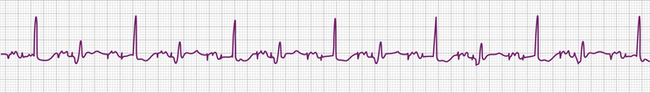
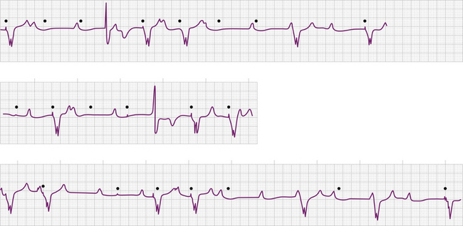
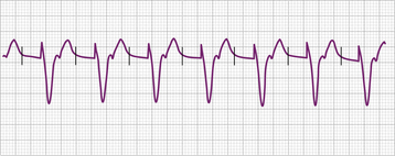
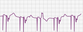
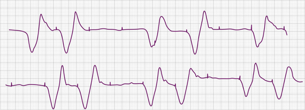
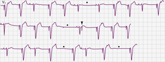
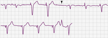
The electrocardiographic diagnosis of failure to capture is made by demonstrating the occurrence of the stimulus output, which, when delivered outside the refractory period of atrial or ventricular tissue, is not followed by a P wave or QRS complex (Figs. 26-1, 26-2, 26-3, and 26-4). The causes of failure to capture fall into one of three major categories: (1) increase in stimulation threshold from various causes; (2) defective pacing leads; and (3) pulse generator battery depletion. It is important to note that stimulus delivery during tissue refractoriness is not true failure to capture, and is designated “functional noncapture.”
Failure to capture is usually due to an increase in atrial or ventricular stimulation threshold. An increase in myocardial stimulation threshold can occur under several circumstances (Table 26-5). Increase in stimulation threshold is the most common cause of failure to capture that occurs in the first 8 weeks after pacemaker implantation and is due to the maturation process at the interface of the electrodes and myocardial tissue. This problem can be managed by noninvasively reprogramming the energy output of the pulse generator to a higher value (by increasing the pulse duration or the voltage amplitude or both). The stimulation threshold decreases to a stable level after 2 months, at which time the energy output can be reprogrammed to a lower value to prolong the battery life. The use of corticosteroid-eluting pacing leads has decreased the local tissue reaction and the thickness of the fibrous capsule surrounding the tip electrode,54 reducing both acute and chronic stimulation thresholds.47,48 Although now quite rare, continued increases in capture threshold over months can occur, reaching voltage outputs that could potentially exceed the capacity of the pulse generator.
Table 26–5 Causes of Pacemaker Noncapture
Various metabolic disturbances are known to increase the myocardial stimulation threshold. Although hypoglycemia does not cause important changes in stimulation threshold, severe hyperglycemia (serum glucose level above 600 mg/dL) has been reported to cause a more than 50% increase.55 Hyperkalemia can also increase the stimulation threshold significantly, generally when the serum potassium level exceeds 7 mEq/L (Fig. 26-5).56–59 Although determination of the serum potassium level can take time, there is usually electrocardiographic evidence of hyperkalemia that should suggest this diagnosis: this evidence includes a prolonged P wave duration, loss of visible P waves, markedly prolonged QRS complex duration (spontaneous or paced), and merging of the QRS complex with the ST-T wave (“sine wave” morphology, see Fig. 26-5). Management includes correction of the hyperkalemia and/or temporarily increasing the energy output of the pulse generator by noninvasive programming or both. This latter maneuver is not always successful, however, and simply increasing pulse generator voltage output will not reverse electromechanical dissociation. Both metabolic acidosis and alkalosis can increase the stimulation threshold by as much as 70% to 80%.59 Hypoxemia and hypercarbia can also cause elevation of the capture threshold, which can be reversed by supplemental oxygen and hyperventilation55; although uncommon today, this may be especially relevant during induction of general anesthesia in patients with cardiac pacemakers. Many of these metabolic disturbances occur during cardiopulmonary resuscitation. In patients with cardiac pacing systems who are pacemaker-dependent, correction of these metabolic disturbances is crucial to a successful resuscitation. Despite the foregoing, failure to capture using today’s pacing systems is not common because of both a high safety margin provided by the programmed energy output and improved lead design.
Drugs that affect the excitability of the myocardium can increase the stimulation threshold, especially when high doses are required to achieve a therapeutic effect. All classes of antiarrhythmic agents are used in intensive care units, and many of them have been shown to affect the myocardial stimulation threshold. Sodium channel blockers, including quinidine and procainamide (Vaughn Williams Class IA antiarrhythmic agents), lidocaine and mexiletine (Class IB), and encainide and flecainide (Class IC), have all been reported to increase cardiac stimulation thresholds.60–66 Digitalis, β-adrenergic antagonists (class II antiarrhythmic agents), and angiotensin-converting enzyme inhibitors have no important effect on the pacing threshold.61,64–66a The effect of amiodarone (a Class III antiarrhythmic agent), whether given intravenously or orally, on the pacing threshold is not well defined, although evidence suggests no significant effect.67 Verapamil, a calcium channel antagonist (Class IV antiarrhythmic agents), has been reported to increase capture threshold,61 but this is unusual. Atropine, isoproterenol, corticosteroids, and epinephrine have been shown to decrease the myocardial capture threshold. 66a Successful management of failure to capture because of the effects of antiarrhythmic agents includes rapid detection and correction of any accompanying metabolic disturbance or electrolyte imbalance. Hyperkalemia potentiates the effect of some Class IA antiarrhythmic agents, particularly quinidine.68 Sodium lactate and sodium bicarbonate have been reported to reverse the effects of the sodium channel antagonists quinidine and procainamide.69,70 Removal of quinidine or procainamide by hemodialysis or hemoperfusion is not effective because of their extensive tissue distribution. Noninvasive programming of the pulse generator to a higher energy output may temporarily allow consistent capture until the offending drugs are excreted. As indicated earlier, current pacing systems are only rarely associated with these clinical problems.
Acute myocardial infarction can result in an increase in stimulation threshold and failure to capture. This is usually, but not always, accompanied by sensing problems (usually undersensing). The mechanisms responsible for the elevation of pacing threshold include local hyperkalemia from tissue necrosis, shock, and high levels of certain antiarrhythmic agents. The failure to capture can be intermittent or complete and can present as type I (Wenckebach) or type II exit block (see Fig. 26-5).71,72 The management of failure to capture in the setting of acute myocardial infarction, in addition to correcting any coexisting metabolic or electrolyte disturbances, is to increase energy output by noninvasive programming of the generator. With current early and aggressive treatment strategies in acute myocardial infarction, failure to capture in this clinical setting is uncommon.
Failure to capture can also result from insufficient energy reaching myocardial tissue because of too high a resistance along the lead wire or to leakage or short-circuiting of current before its reaching the electrode-tissue interface. This can be due to lead fracture or lead insulation failure, respectively. Because permanent pacing leads bend with each systole, the cumulative stress on the lead over years can be substantial. Stresses on leads introduced into the subclavian vein are also imposed when they are compressed by soft tissues during movement of the clavicle. In one large, albeit older, study of 2226 patients, the incidence of lead fracture was reported to be 3.9% (1.2% per patient year).73 Common sites of lead fracture are between the connector and the venous entry, with only 7% occurring within the vascular system itself.73 Although complete lead fracture is manifested on the electrocardiogram by the absence of pacing stimulus artifacts (no energy reaching body tissues), a partial fracture, in which the circuit is sometimes “made” or “broken,” is more common, normal sensing and pacing during the “making” of the circuit will be seen, along with intermittent abnormal sensing and pacing function (Fig. 26-6, and see Fig. 26-2). Potential differences between the two ends of a broken electrode can cause electrical signals (“false” signals) that can be sensed, resulting in pauses in pacing stimulus intervals in single chamber devices and either pauses or earlier-than-expected ventricular stimulation in dual chamber systems, the cause of which is not readily apparent. Applying the magnet over the pulse generator, which disables the sensing function, can secure the diagnosis of oversensing due to lead fracture if the visible interstimulus intervals are a multiple of the basic pacing rage (Fig. 26-7). Highly penetrated chest radiographs in both posteroanterior and lateral views should be performed and evidence of a lead fracture should be carefully sought. Interrogation of the pacing system will reveal high lead impedance along the fractured lead, reflecting discontinuity within the lead. Lead wire fracture with failure to capture can be an emergency if the patient is pacemaker dependent.
Lead insulation failure can cause current to leak into body tissues and insufficient current to be delivered at the myocardium to cause depolarization, with resultant failure to capture. An insulation break can be caused by needle nick damage at the time of pacemaker pocket closure or, much less commonly today, by degradation due to design-related failure.74,75 Inappropriate sensing of unwanted signals generated by the current leak (oversensing) may coexist. On the electrocardiogram, a bipolar lead with an insulation break may manifest a larger than usual pacing stimulus artifact; the pacing artifact polarity may also change. Comparison should be made with a baseline 12-lead analog electrocardiogram for magnitude and polarity of the pacing artifacts. The definitive diagnosis of lead insulation failure can be made by interrogation of the pacing system, which demonstrates lead resistance below the normal range for the particular lead in question.
Lead displacement, including myocardial penetration and perforation, is a common cause of failure to capture early after implantation. Undersensing usually coexists. When suspected, highly penetrated radiographs of the chest in both posteroanterior and lateral views should be obtained and compared with those taken immediately after pacing system implantation. A 12-lead electrocardiogram should also be obtained so that the morphology of the paced QRS complexes can be compared. Once lead dislodgement is confirmed, repositioning is usually required, although occasionally output and sensing threshold programming can restore normal pacing system function. The use of active and passive fixation leads in the atrium and ventricle has largely obviated the problem of lead dislodgement in permanent pacing systems, although the problem still exists in the temporary pacing setting.
Failure of Output
Failure of output is manifested on the surface electrocardiogram as an absence of pacing artifacts. Absence of pacing stimuli due to failure of output should not be confused with absence of visible pacing stimuli due to lead fracture, loose connections between the pulse generator and the leads, oversensing, and low programmed voltage generating low amplitude artifacts (see Figs. 26-6 and 26-7); in these circumstances, pacing pulses are emitted by the pulse generator in the normally expected manner.
Sensing Problems
Problems related to sensing the intracardiac electrical signal can be conveniently divided into those caused by oversensing of unwanted signals or undersensing of the intrinsic intracardiac signal (Figs. 26-8, 26-9, 26-10, and 26-11; Tables 26-6 and 26-7). In asynchronous or magnet mode of pacing (AOO, VOO, DOO), the sensing function is disabled and fixed-rate pacing at the manufacturer-specific magnet rate and other intervals, such as the AV interval, result. Appropriate sensing in the atrium and ventricle is an indispensable part of pacemaker function. Several factors influence sensing functions, including the lead configuration (bipolar versus unipolar), the amplitude and the slew (rate of change of voltage [dV/dt]) of the intracardiac signals, and the sensitivity setting (sensing threshold) of the pacemaker generator. The pacemaker “senses” the voltage difference between the two electrodes (anode and cathode) of the pacing system. In unipolar systems, one electrode (the cathode) is the tip of the pacing wire and the other electrode (the anode) is the pacemaker generator itself. The large antenna thus created enlarges the intracardiac signal (and extracardiac signals), allowing for easier sensing. In bipolar pacing systems, the electrodes are in proximity to each other on the lead; the sensed signal is between the closely spaced electrodes. Although studies indicate little difference in the sensed signal between unipolar and bipolar lead configurations, on occasion, in the acute setting unipolarization of a temporary pacing system can be useful.76 Unipolarization can also be used in permanent pacing systems in some cases of lead insulation break to re-establish normal pacing and sensing function, at least temporarily.
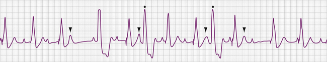
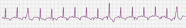
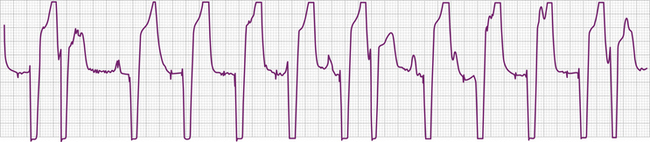
Table 26–6 Causes of Oversensing
Table 26–7 Causes of Undersensing
The intracardiac ventricular signal is generally between 6 and 15 mV and the atrial signal is generally 1 to 4 mV. A signal with a lower slew such as one originating in ventricular tissue is more likely not to be sensed than one with a high slew rate. After each pacing output pulse and after every sensed spontaneous cardiac signal, atrial and ventricular refractory periods are initiated during which the pacemaker will not respond to incoming signals (Table 26-8). The refractory period in the ventricular channel is usually programmed between 250 and 400 milliseconds to prevent sensing of the late part of the QRS complex and T wave. T wave oversensing can occur if the refractory period is programmed too short or if the sensitivity is too low (see Fig. 26-8).
Table 26–8 Parameters of Cardiac Pacing System Relevant to the Critical Care Unit
| Rates: • Upper rate limit: the highest rate at which the pacemaker will output; either in response to the atrial rate (“atrial driven”) or to sensor input (“sensor driven”) • Magnet: the rate during application of the magnet. This rate will differ depending on the manufacturer and the model of the pacemaker • Elective replacement indicator (ERI): the (usually magnet) rate that indicates the elective replacement time for a particular pulse generator |
| AV interval: The interval between the atrial and ventricular stimulus delivery, or between the time of sensing the atrial depolarization and the delivery of the ventricular stimulus (this can be a dynamic value, changing with rate and other factors) |
| Refractory period: The interval during which the pulse generator will not respond to electrical signals, independently programmable for atrial and ventricular channels |
| Pacemaker energy output: The factors in the output are voltage, current, and pulse duration contemporary pacemaker generators allow programming of the voltage and pulse duration; to control energy output; independently programmable for atrial and ventricular channels |
| Sensitivity: The amplitude of the electrical signal that the pulse generator is programmed to sense, independently programmable for atrial and ventricular channels |
| Mode of function: See Table 31-4. The mode programming operation in the critical care setting is to program from dual-chamber to single-chamber (almost always ventricular) mode of operation to prevent rapid paced ventricular rates due to tracking of atrial tachyarrhythmias. |
Oversensing
Oversensing is present when the polar generator sensing circuit identifies an electrical event sensed in the ventricular channel as an R wave or an electrical event sensed in the atrial channel as a P wave (see Figs. 26-7 and 26-8). These electrical events may be generated in the pacing system itself, in the heart, in the body musculature, or in the environment (see Table 26-6). The consequence of oversensing is a pause in paced rhythm (AAI or VVI modes) or, if the oversensed atrial event causes triggered pacing in the ventricle, an earlier than expected paced ventricular event (DDD modes may have either response, depending on where the impulse was oversensed). Appropriate pacing function can be demonstrated by placing the magnet over the pulse generator, temporarily disabling sensing function (AOO, VOO, DOO modes). This maneuver serves to exclude failure of output as a cause of absent pacing artifacts and can also clarify a diagnosis of lead fracture.
Related posts:
 Evolution of the Coronary Care Unit: Past, Present, and Future
 Elevated Cardiac Troponin in the Absence of Acute Coronary Syndromes: Mechanism, Significance, and Prognosis
 Hemodynamically Unstable Presentations of Congenital Heart Disease in Adults
 Conduction Disturbances in Acute Myocardial Infarction
 Antiplatelet Therapy
 Invasive Hemodynamic Monitoring in the Cardiac Intensive Care Unit
Stay updated, free articles. Join our Telegram channel

Full access? Get Clinical Tree


