Chapter 49 Mechanical Ventilation and Respiratory Care
Vesalius, in 1555, was one of the first to suggest that artificial respiration in humans is possible by blowing air through a tube of reed or cane positioned in the trachea.1 Positive pressure ventilation was first used in conjunction with general anesthesia in the 1920s.2 Outside the operating room environment, mechanical ventilation during the 1920s was provided by negative pressure methods.3 The utility of prolonged artificial respiration was first proven in the management of polio victims, where it was primarily used to maintain breathing until patients could recover their muscle strength.4 Since then, tremendous advances have been made not only in the design and sophistication of mechanical ventilators, but also in the application of artificial respiration in its varied modes for a variety of illnesses and indications. This chapter will review the following: (1) applied physiology of breathing, (2) a conceptual framework for the design and function of mechanical ventilators, (3) a modern classification to understand the modes of mechanical ventilation, (4) practice parameters for mechanical ventilator support based on the pathophysiology, (5) philosophy and the practice of weaning, (6) the theory and practice of adjunctive respiratory care, (7) the theory and practice of high frequency ventilation, and (8) home respiratory care. The topic of noninvasive mechanical ventilation is covered elsewhere (Chapter 50).
Applied Respiratory Physiology
Physiology of Inflation and Deflation
Thoracic structures impede lung inflation. Therefore a certain amount of force is required to overcome this impedance. One of the major determinants of impedance to lung inflation is elasticity of the lung and chest wall. Compliance, a measure of elasticity, is defined as the change in volume per unit change in transmural pressure. Lung compliance is defined as the change in lung volume for a unit change in transalveolar pressure (alveolar pressure minus the pleural pressure). Chest compliance is the change in thoracic cage volume produced by a unit change in transthoracic pressure (ambient pressure minus the pleural pressure). Specific lung compliance refers to lung compliance that is normalized to the lung volume or body weight and is similar in children and adults. Disease processes that result in an abnormal lung or chest wall compliance are given in Box 49-1. The second major determinant of impedance to lung inflation is airway resistance. Airway resistance is defined as the change in transpulmonary pressure (proximal airway pressure minus the alveolar pressure) required to produce a unit flow of gas through the airways of the lung. In the infant, the airway resistance is equally distributed between the upper and lower airways. With increasing age, most of the airway resistance resides in the upper airways. Two additional factors impede inflation. One is inertia of the respiratory gas, or inertance.5 The other is the frictional resistance to deformation of the lungs, thoracic cage, and abdominal contents.5 Frictional resistance is also known as the nonelastic viscous resistance. Therefore, taking into consideration all the forces that impede lung inflation, the total pressure (Ptp) required to inflate the lung can be mathematically expressed as follow,s termed the equation of motion:
Box 49–1 Factors Associated with Decreased Total Respiratory Compliance

where PCompliance is the pressure required to overcome the compliance of the respiratory system, Presistance is the pressure required to overcome the resistance of the airways, PInertance is the pressure required to overcome inertance, and PFrictional resistance is the pressure required to overcome the frictional or tissue resistance to deformation of the lungs, thoracic cage, and abdominal contents.

where Elastance is the reciprocal of compliance.


It takes a finite amount of time to inflate the lung with a given volume of gas. This factor is directly proportional to the compliance and the resistance. Time constant is the product of compliance and resistance, and it defines the time taken to cause a given change in lung volume with a constant distending pressure. The rate of inflation and deflation of the lung is normally exponential; one time constant is the time taken to cause a 63% change in volume, and three time constants is the time taken to cause a 95% change in volume.5 Normal expiration is passive because of the elastic recoil of the lung. Elastic recoil of the lung is attributable to alveolar surface tension and tissue elasticity. Surface tension is greatest at high lung volumes, and lowest at FRC. Elastic recoil of the lung provides most of the force required to expel the gas from the lungs. Again, the time taken to expel a certain tidal volume depends on the time constant of the respiratory system. Because inspiratory and expiratory resistances are different, inspiratory and expiratory time constants may be different.
Work of Breathing
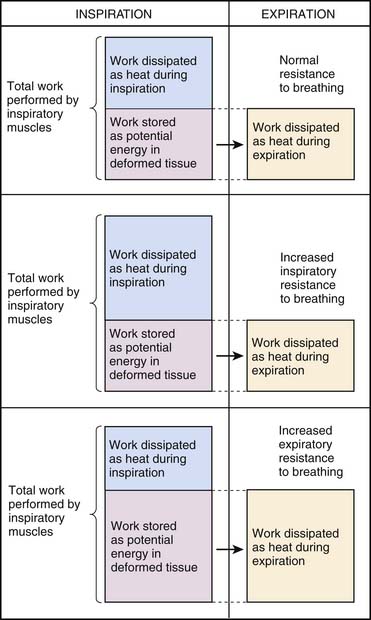
During normal tidal breathing, the work of breathing is performed entirely by the inspiratory muscles (Figure 49-1), and almost all of the work is performed during inspiration. Nearly half of the work of breathing during inspiration is dissipated as heat to overcome frictional resistance to deformation.5 The remaining inspiratory work is stored as potential energy that is used to perform the expiratory work. Increased airway resistance and decreased chest and lung compliances would require a greater Ptp to inflate the lung to the same lung volume. This imposes a greater workload on the respiratory muscles and increases the oxygen cost of breathing. When the oxygen supply/demand balance to the respiratory muscles is perturbed, respiratory failure may ensue because of muscle fatigue.
Determinants of Gas Exchange
The determinants of systemic arterial oxygenation are inspired oxygen concentration and tension, lung volume, cardiac output, ventilation/perfusion (V/Q) matching, and the magnitude of venous admixture or intrapulmonary shunting. Lung volumes are increased during inspiration and fall during expiration. During expiration, the presence of alveolar surfactant prevents alveolar collapse. A critical opening pressure is required to maintain both the patency of the terminal airways and alveolar volume. When the airway pressure is below the critical opening pressure, the terminal airway closes and the alveoli collapse because of continued absorption of gases into the bloodstream. Surfactant deficiency, loss, or alteration promotes alveolar collapse and increases the critical opening pressure. In parenchymal lung disease, which is characterized by an increased critical closing pressure, alveoli collapse during expiration if the airway pressures cannot be maintained above the critical opening pressure. Alveolar collapse leads to inadequate oxygenation from increased intrapulmonary shunting resulting from V/Q mismatch.
Inadequate ventilation results from a minute alveolar ventilation that is insufficient to meet the metabolic production of carbon dioxide. PaCO2 reflects the balance between metabolic production of carbon dioxide and its elimination. Failure of carbon dioxide elimination usually results from hypoventilation due to decreased central drive, lower airway obstruction, parenchymal disease, and muscle weakness (Box 49-2). Increased metabolic production of carbon dioxide usually results from hypermetabolic states and excessive caloric intake, especially high carbohydrate alimentation.
Indications for Mechanical Ventilation
Respiratory Failure
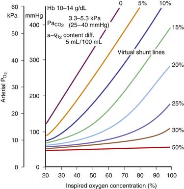
The primary indication for institution of assisted ventilation is respiratory failure. Apnea or respiratory arrest is an extreme form of respiratory failure and an absolute indication for mechanical ventilation. Respiratory failure is generally defined as the presence of (a) inadequate oxygenation, (b) inadequate ventilation, or (c) both. Inadequate oxygenation, objectively, is defined as partial pressure of arterial oxygen (PaO2) less than 60 torr or an arterial hemoglobin oxygen saturation of less tha 90% in room air. Oxygenation can also be expressed as the ratio of PaO2 to fractional concentration of oxygen in inspired gas (FiO2). Inadequate oxygenation can also be defined as a Pao2/FiO2 ratio of less than 300. Other indexes include an alveolar/arterial oxygen gradient of more than 300 torr with an FiO2 of 1.0 and a calculated or measured intrapulmonary shunt fraction greater than 15%. Inadequate oxygenation due to intrapulmonary shunting can be overcome with the addition of increased inspired oxygen concentration, provided the magnitude of the shunt is less than 15% (Figure 49-2). Intrapulmonary shunt can be decreased by with the reexpansion of collapsed alveoli or with the decrease of the fraction of pulmonary blood flow going to the collapsed alveolar segments. Inadequate ventilation is defined as PaCO2 greater than 45 torr with an arterial pH of less than 7.35 in the absence of chronic hypercapnia. Impending respiratory failure, characterized by rapidly rising PaCO2, progressive respiratory distress, PaCO2 out of proportion to the respiratory effort, or fatigue of respiratory muscles, is a relative indication for mechanical ventilation. Intubation and institution of mechanical ventilation in impending respiratory failure are likely to be more controlled than when full-blown respiratory failure develops. Therefore in critically ill children, establishing mechanical ventilation before respiratory failure develops is preferable. Chronic respiratory failure is defined as requirement for mechanical ventilation for more than 28 days. Children with chronic lung disease often fail to grow despite adequate caloric intake. In these patients, mechanical ventilation may decrease the work of breathing enough to allow the child to grow.
Cardiovascular Dysfunction
Moderate to severe cardiovascular dysfunction is another major indication for mechanical ventilation. The cardiovascular and respiratory systems must act in concert to maintain adequate gas exchange and thereby meet the metabolic demands of the whole body. Therefore the two systems cannot be functionally divorced from each other (until death do these part, unless one is undergoing extracorporeal membrane oxygenation [ECMO]). Cardiovascular dysfunction results in decreased respiratory reserve, in increased respiratory work, and may ultimately result in respiratory failure. Positive pressure ventilation decreases lactic acid production by respiratory muscles during circulatory shock, and withdrawal of ventilatory support results in a marked increase in cardiac work.6,7 Therefore mechanical ventilation not only may decrease the work of breathing under these circumstances but also decrease the oxygen demand of the heart.
Design and Functional Characteristics of Mechanical Positive-Pressure Ventilators
A detailed review of the physical characteristics and functional design of ventilators is beyond the scope of this chapter, and the reader is referred to several excellent reviews on this subject.8–13 In 1991, Chatburn proposed a new system for understanding the design of mechanical ventilators.10 A Consensus Conference on the Essentials of Mechanical Ventilators was held in Cancun, Mexico, in February 1992 and the proceedings published in the September issue of the Respiratory Care Journal. The goals of the conference were to (1) provide a standard nomenclature, (2) identify essential support features, (3) identify essential heat and humidity requirements, (4) identify essential monitoring/alarm features, and (5) identify what constitutes an order for mechanical ventilation. There are four key reviews that have increased our understanding of a standard nomenclature to classify mechanical ventilators and modes of ventilation.10a–13 The scheme to classify mechanical ventilators was based on features of input power, control scheme, and the output variables (Box 49-3). Subsequent modifications to include newer modes of ventilation are described elsewhere.11–13 The following is a brief summary that incorporates some of the elements of Chatburn’s classification.
Box 49–3 Outline of Ventilator Classification System
From Chatburn RL: Classification of mechanical ventilators, respiratory care equipment, Philadelphia, 1995, JB Lippincott.
Ventilator as a Machine
The concept is a simple one—a ventilator is simply a machine that performs external work. This requires energy to be applied to the device which is then altered, transmitted, and directed in a predetermined manner to perform the work of breathing. This work can either replace the patient’s work of breathing completely or partially or augment a patient’s breathing efforts. Therefore a ventilator is a mechanical device that is used to move gas into the lungs by increasing Ptp. Positive pressure ventilators create Ptp by raising the airway pressure (Paw) above the intrapleural pressure (Ppl), whereas negative pressure ventilators create Ptp by decreasing Ppl below Paw. All ventilators include an input power, a drive system, a control system, a cycling mechanism, and a system to provide positive end-expiratory pressure (PEEP).8–13 The accessories include a heated humidifier and an oxygen blender. The input power provides the energy to operate the ventilator and is usually electric or pneumatic. The drive system provides the force required to generate a gas flow. For gas flow to be provided, a pressure gradient needs to be created between the ventilator and the lungs. This is most commonly accomplished with compressed gases at high pressures from wall outlets or cylinders or a small compressor designed to be used with individual ventilators. Alternatively, some ventilators have a built-in compressor such as a piston and cylinder (e.g., Emerson IMV), a diaphragm (e.g., Engtrom Erica), a system of bellows (Siemens Servo 900C), or a rotating vane (Bear 2). When a ventilator depends on an external source of compressed gases to power the ventilator, it acts mainly as a control system and will not function if the external source fails. On the other hand, a ventilator that has an internal compressor does not need an external source of gas to inflate the lung. The pressure generated within the ventilator can be thought of as the driving pressure that forces the gas into the lungs through the conducting system involving the ventilator circuit and the patient’s airways. During mechanical ventilation, for a single breath, Ptp may be generated either by the ventilator or a spontaneous breath or a combination of both. Therefore the equation of motion can be reexpressed as:
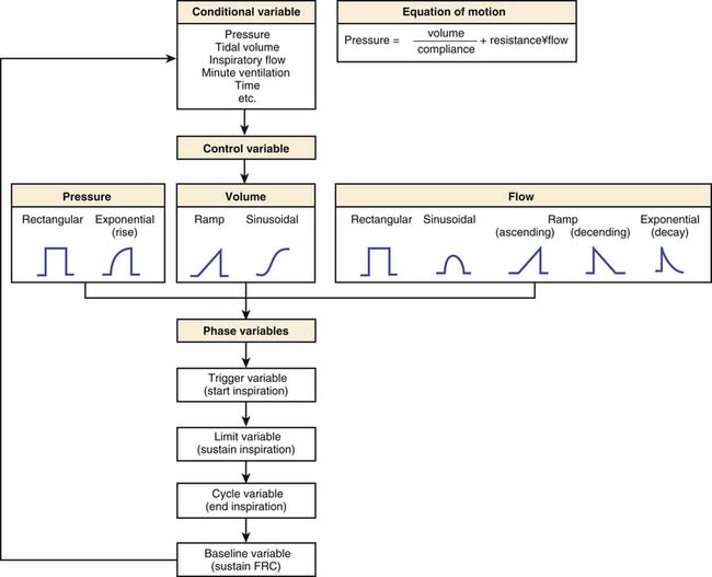
where Pmus is the pressure exerted by the respiratory muscles and Pvent is the pressure exerted by the ventilator. Compliance and resistance are assumed to remain constant during lung inflation and are called parameters. Pressure, volume, and flow in the respiratory system change with time and are therefore referred to as variables. Figure 49-3 shows the classification scheme that is based on the equation of motion.
A ventilator can also be viewed as a form of mechanical controller that “controls” either pressure (in a pressure generator) or flow (in a flow generator). A pressure generator is a ventilator that generates a fixed pattern of pressure within the ventilator and at the mouth regardless of the lung conditions, leaving the flow waveform free to vary. This occurs when the generated pressure is low (generally between 20 and 50 cm H2O), which results in a high initial flow rate that decays to zero as the alveolar pressure approaches the generated pressure. The generated pressure can be constant, nonconstant, increasing, or decreasing. The Hand-E-Vent (Ohio Medical Products), Bird Asthmatik (Bird Corporation), the Bennett PR-1, and the Bennett PR-2 ventilators are examples of pressure generators. A flow generator is a ventilator that generates a high driving pressure (3 to 50 psig corresponding to 200 to 3500 cm H2O) and controls the inspiratory flow of gas into the patient by interposing a high series resistance system between the generated pressure and the patient. The flow generated may be constant, nonconstant, increasing, or decreasing.
The pattern of gas flow from the ventilator to the patient depends on the driving mechanism and the driving pressure in the ventilator. Four distinct flow patterns can be recognized: (1) a constant flow, (2) a decelerating flow, (3) an accelerating flow, and (4) a sinusoidal or sine-wave flow (Figures 49-4 to 49-6). A constant inspiratory flow is generated when the driving pressure is very high (e.g., 50 psig) relative to the airway pressure. The drive mechanism is usually a high-pressure gas system (compressed air or oxygen at 10 to 50 psig). The driving force may exceed 1000 cm H2O and is severalfold higher than the typical proximal airway pressure that is required to inflate the lungs. An adjustable resistance controls the pressure and the flow to the proximal airway. The airway pressure and lung volume increase linearly until inspiration is terminated. Bird Mark 7 and Monaghan 225/SIMV are examples of high pressure drive systems with constant inspiratory flows. Constant flow can also be generated by a linear-driven piston, which moves at a constant rate of speed during inspiration (e.g., Bourns LS 104-150 Infant Ventilator). A decelerating inspiratory flow is created when the driving pressure is relatively low (<60 cm H2O). In this case, a pressure-reducing valve controls the driving pressure to the desired level. As the airway pressure and lung volume increase during inspiration, the pressure gradient between the drive mechanism and the proximal airway decreases. Consequently, as inspiration continues, the inspiratory flow from the ventilator decreases and finally stops at the end of inspiration. The Bennett PR-1 and PR-2 are examples of low-pressure drive systems that produce decelerating inspiratory flows. A sine-wave or sinusoidal inspiratory flow is created when the drive mechanism is a rotary driven piston. As the rotary wheel turns, the piston is moved to and fro in the cylinder in an accelerating and then a decelerating fashion. The inspiratory flow produced also has a similar profile. Emerson 3-PV and 3-MV ventilators are examples of rotary piston devices. The notion that one specific flow pattern is more beneficial than the others is controversial. A detailed description of this topic is beyond the scope of this chapter, and the reader is referred to several excellent reviews.8–13 Ventilators can also be classified as a single-circuit or a double-circuit device. A single-circuit device refers to a ventilator in which the gases go directly from the drive mechanism to the patient (e.g., Emerson-PV and 3-MV models, Bird Mark series, and the Siemens Elema 900 series ventilators). On the other hand, a double-circuit device refers to a system in which the drive mechanism is used to compress another system that then delivers the tidal volume (e.g., Engstrom 150 and 300 series, Bennett MA-1, and Monaghan225/SIMV ventilators).
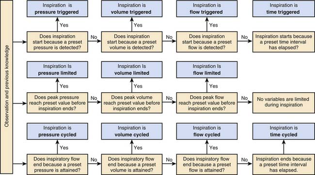
All ventilators are equipped with mechanisms to provide four basic functions: (1) inflate the lungs, (2) terminate lung inflation, (3) allow lungs to empty, and (4) start lung inflation.10,11 The ventilator performs these functions through four phases: (1) the inspiratory phase, (2) the changeover from the inspiratory to the expiratory phase, (3) the expiratory phase, and (4) the changeover from the expiratory phase to the inspiratory phase. The criteria for determining the phase variables during a mechanical breath are shown in Figure 49-7. The inspiratory phase is started when a variable measured in the circuit or at the airway reaches a preset value. This variable can be pressure, volume, flow, or time. This is called the trigger variable. Pressure- or flow-triggering requires a patient effort. On the other hand, time-triggered breaths do not require a patient effort but can be synchronized to the patient’s efforts. During inspiration, a tidal breath is delivered to the lung. The volume of the tidal breath delivered to the patient depends on several factors: (1) the Ptp generated, (2) the compliance and resistance of the ventilator circuit, (3) the impedance to inflation of the patient’s lungs, (4) leaks in the circuit, (5) leaks around the endotracheal tube, and (6) limitation or regulation of inspiratory phase variables (pressure, flow, or volume). Limitation or regulation of the inspiratory pressure, volume, or flow does not terminate inspiration. Modern ventilators such as the Siemens Servo 300 can control more than one phase variable during inspiration. Termination of inspiration depends on the cycling mechanism. Cycling refers to the mechanism by which inspiration is terminated and expiration is initiated. All ventilators require a trigger mechanism to cycle. The trigger for cycling may be a predetermined time (time cycling), a predetermined pressure (pressure cycling), a predetermined volume (volume cycling), or a predetermined flow (flow cycling). Most conventional ventilators used in infants and children today are time-cycled or volume-cycled ventilators.
Modes of Ventilation
Mode of ventilation can be defined as the manner in which a ventilator achieves the objectives of mechanical ventilation.12 In 2007, Chatburn proposed an update which simplified the nomenclature so that all modes of ventilation can be adequately described.13 Box 49-4 describes the classification scheme from that review.13 A breath refers to the occurrence of a positive airflow into the lungs (inspiration) and a negative airflow out of the lungs (expiration), which results in ventilation of the lungs. The positive and negative airflow are relative to a baseline. As described previously, all breaths have four important components. They are inspiratory trigger, phase of inspiration, termination of inspiration and the start of expiration (otherwise called cycling), and the phase of expiration.
Box 49–4 Chatburn’s Classification Scheme for Modes of Ventilation
Modified from Chatburn RL, Primiano FP Jr: A new system for understanding modes of mechanical ventilation, Respir Care 46:604–621, 2001; and Chatburn RL: Classification of ventilator modes: update and proposal for implementation, Respir Care 52:301–323, 2007.
There are eight possible breathing patterns based on three possible control variables (volume, pressure, and dual control) and three breath sequences.12,13 These are shown in Table 49-1. Continuous spontaneous ventilation (CSV) refers to a breath sequence in which all the breaths are spontaneous. Continuous mandatory ventilation (CMV) refers to a breath sequence in which all the breaths are mandatory breaths. During CMV, spontaneous breaths are not permitted or do not occur between mandatory breaths. If the patient is breathing spontaneously during CMV, each spontaneous breath may trigger a mandatory breath. Assist-control refers to a mode of ventilation when a patient receives a combination of ventilator-initiated and patient-initiated mandatory breaths. The total number of mechanical breaths will be the sum of the preset frequency of ventilator breaths and the number of patient-triggered breaths. For example, if the preset frequency is 15 breaths/min and the patient triggers an additional 15 breaths/min, the total number of mandatory breaths will be 30 breaths/min. Mandatory breaths may be superimposed on spontaneous breaths (such as during high frequency) or vice versa (such as during airway pressure release ventilation). Intermittent mandatory ventilation (IMV) refers to a breath sequence where breaths are either mandatory or spontaneous. Volume control CSV is not possible because the definition of a spontaneous breath would conflict with the definition of volume control. When all minute ventilation is provided by the ventilator, it is referred to as total ventilatory support. When some of the minute ventilation is provided by spontaneous breathing and the rest by the ventilator, it is referred to as partial ventilatory support. Total ventilatory support is provided when the patient does not take any spontaneous efforts because of a primary disease process (e.g., quadriplegia, muscle disease), pharmacologic therapy (e.g., induced neuromuscular blockade), or suppression of spontaneous breathing efforts (e.g., hyperventilation). Total ventilatory support is provided entirely by CMV. On the other hand, partial ventilatory support can be provided by CMV, AMV, or a combination of both.
| Breath-Control Variable | Breath Sequence | Acronym |
|---|---|---|
| Volume | Continuous mandatory ventilation | VC-CMV |
| Intermittent mandatory ventilation | VC-IMV | |
| Pressure | Continuous mandatory ventilation | PC-CMV |
| Intermittent mandatory ventilation | PC-IMV | |
| Continuous spontaneous ventilation | PC-CSV | |
| Dual | Continuous mandatory ventilation | DC-CMV |
| Intermittent mandatory ventilation | DC-IMV | |
| Continuous spontaneous ventilation | DC-CSV |
Modified from Chatburn RL, Primiano FP Jr: A new system for understanding modes of mechanical ventilation, Respir Care 46:604–621, 2001; and Chatburn RL: Classification of ventilator modes: update and proposal for implementation, Respir Care 52:301–323, 2007.
Mandatory Mechanical Ventilation
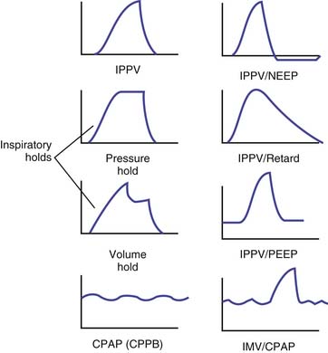
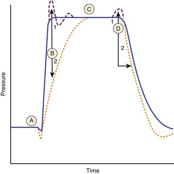
During inspiration, the control variable is pressure (pressure control), volume (volume control), flow (flow control), time (time control), or dual control. The two most common forms of controlled mandatory mechanical ventilation modes that are used in infants and children are pressure-regulated and volume-regulated mandatory modes of ventilation. Figure 49-8 shows pressure-time curves for some of the mandatory modes of ventilation.
Volume-Regulated Mandatory Breaths
Most modern ventilators deliver the preset tidal volumes reliably, but the tidal volumes delivered to the patient on a breath-to-breath basis may not always be constant. The tidal volume delivered by the ventilator is distributed between the ventilator circuit, the airways, and the patient’s lungs. The compliances and resistances of the ventilator circuit, the endotracheal or tracheostomy tube, and the patient independently and together affect the distribution of tidal volume delivered by the ventilator. A decrease in the compliance or an increase in the resistance of the ventilator circuit will affect the actual tidal volume delivered to the patient. The ventilator circuit includes an internal volume and the external tubing. The actual tidal volume or the effective tidal volume (VTeff) delivered to the patient can be approximated by the following formula:

where VTdel is tidal volume delivered by the ventilator and VTcircuit is the volume of gas that is distributed to the ventilator circuit. VTdel is equal to the inspired tidal volume, when there is no leak in the total respiratory system. When there is a leak in the system, however, such as with the use of uncuffed endotracheal tubes, then VTdel is less than the inspired tidal volume. VTcircuit can be estimated by the following formula:

where Cvent is the compliance of the ventilator circuit. An increase in resistance or compliance of the ventilator circuit (including the endotracheal tube) or the patient’s airways or lungs will increase the time constant to inflation. If the inspiratory time is less than five times the time constant of the whole respiratory system, which includes the ventilator circuit and the patient’s airways, then the VTdel will be less than the preset tidal volume. During inspiration, after the tidal volume is delivered, an inspiratory hold will maintain inspiratory pressure and prolong the duration of inspiration (see Figure 49-8). During exhalation, expiratory flow curves depend on the type of expiratory resistance or PEEP valve in the system.
Pressure-Regulated Mandatory Breaths
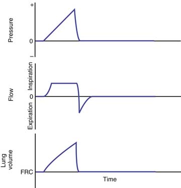
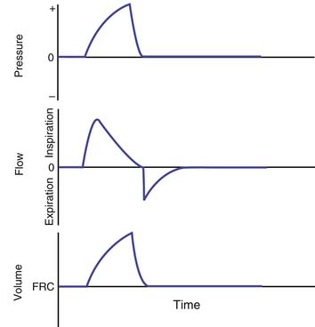
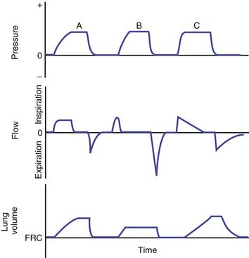
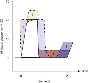
Pressure-regulated ventilation can be either pressure-cycled or pressure-limited time-cycled ventilation. In pressure-cycled ventilators, inspiration is terminated when a preset pressure limit is reached. In this mode of ventilation, the inspiratory time may vary depending on the changes in resistance and compliance of the total respiratory system. This mode of ventilation is not widely used these days except for intermittent positive-pressure breathing treatments. Pressure-limited, time-cycled ventilation is most commonly used in the neonate with respiratory distress syndrome and in children with acute respiratory distress syndrome (ARDS). In this mode, inspiratory and expiratory times are constant, and the PIP reaches a preset limit quickly early in inspiration and is then maintained at that level during the rest of the inspiratory phase. Usually a high flow rate is used (4 to 10 L/kg/min). The tidal volume delivered depends on the compliance and resistance of the ventilator circuit and the patient’s lungs. Pressure-controlled ventilation results in higher mean airway pressure for the same amount of minute ventilation. Figure 49-9 shows the time course of changes in airway pressure, inspiratory flow, and lung volume with normal lungs, lungs with decreased compliance and with increased resistance. As shown in Figure 49-9, with PIP remaining the same, lung volume delivered is affected by changes in lung compliance and airways resistance. Factors that would increase mean airway pressure during pressure-controlled ventilation are shown in Figure 49-10.
Continuous Flow Versus Demand Flow
Some ventilators that can provide pressure-regulated ventilation have both inspiratory and expiratory valves. Once PIP is reached, both inspiratory and expiratory valves close and the lung is held in inflation until the end of inspiration. For use in infants, ventilators were modified to provide continuous flow throughout the respiratory cycle.14 A continuous flow device refers to a ventilator in which the flow of respiratory gas occurs throughout the respiratory cycle. Most infant ventilators are continuous flow devices (e.g., Infant Star, Baby Bird). In most continuous flow infant ventilators, inspiratory valves are lacking, and the cycling is controlled by the exhalation valve. Closure of the exhalation valve begins inspiration, and the flow of gas going through the circuit is diverted to the patient. If the inspiratory flow rate is low (1 to 3 L/kg) and if the PIP is not limited, the tidal volume delivered by the patient can be calculated from the inspiratory flow rate and the inspiratory time. This would result in a time-cycled, volume-regulated breath. For pressure-control ventilation, the flow rates used are usually higher (4 to 10 L/kg). Once the preset PIP is reached, the excess flow is vented through a pressure relief valve, and the lungs are maintained in inflation throughout the rest of inspiration. During exhalation, there is continuous flow of gas, allowing the patient to breathe from the circuit rather than open a demand valve. A demand flow ventilator refers to a ventilator that allows inspiratory flow of gas to the patient between ventilator breaths through a demand valve that is opened by the patient’s inspiratory efforts. Work of breathing is higher with a demand flow ventilator compared with a continuous flow device because of the effort required to open the demand valve.
Intermittent Mandatory Ventilation
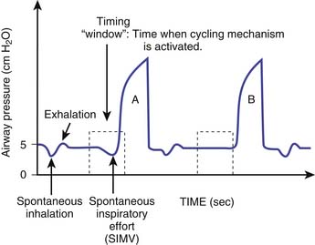
Intermittent mandatory ventilation (IMV) refers to a pattern of controlled ventilation in which spontaneous breathing is permitted. Between mandatory machine breaths, the patient can breathe spontaneously and the required gas flow is delivered through either a continuous flow or a demand system. The concept of IMV where spontaneous breathing occurred with a preset mechanical ventilator rate was first developed by Kirby et al.14 in 1971 with the use of a continuous flow circuit in the management of respiratory distress syndrome of the neonate. IMV was first described by Downs et al.15 in 1973 to describe a mode of ventilation that allowed the patient to breathe spontaneously with a preset ventilator rate. The spontaneous breaths are not assisted by a ventilator breath. Therefore the tidal volumes generated by the spontaneous breaths depend on the patient’s effort alone and not on the ventilator support. The total ventilatory support time and duration of weaning were significantly reduced in infants using IMV compared with CMV.16,17 Two systems are currently available to deliver IMV: one uses continuous flow, and the other uses a demand valve. Ventilators such as the InfantStar incorporate a continuous flow circuit that can be adjusted to the inspiratory flow demand of the patient. The ideal flow rate would result in minimal pressure swings associated with spontaneous inspiration and expiration. Most modern ventilators incorporate a demand valve that needs to be opened to satisfy the inspiratory flow requirements of the patient. This increases the inspiratory work of breathing. This can be minimized by the application of a small amount of pressure support. When IMV is synchronized to the patient’s inspiratory efforts, it is referred to as synchronized IMV (SIMV) (Figure 49-11). The ventilator accomplishes this by creating a timing window just before the next mandatory breath is scheduled to be delivered. If the patient takes a spontaneous breath in this timing window and the ventilator senses this breath on the basis of the trigger sensitivity, then the mandatory breath is synchronized with the patient’s effort. Each time a synchronized breath is delivered, the machine recomputes the time required to deliver the next mandatory breath. In SIMV, the total number of mandatory breaths will only be equal to the preset frequency of mandatory breaths. SIMV breaths can be both volume regulated or pressure limited.
Continuous Positive Airway Pressure/Positive End-Expiratory Pressure
CPAP refers to the maintenance of positive airway pressure throughout the respiratory cycle with no positive pressure breaths being delivered to the patient. PEEP refers to the maintenance of positive airway pressure above atmospheric pressure at the airway opening at end expiration.18 CPAP/PEEP can be applied by a variety of devices. These include (1) an underwater column, (2) a water-weighted diaphragm, (3) a Venturi valve, (4) a spring-loaded valve, (5) a pressurized exhalation valve, (6) a magnetic valve, and (7) a fixed or adjustable orifice. Devices that retard expiratory flows (e.g., Venturi valve, fixed or adjustable orifice) tend to produce higher mean airway pressure than those that do not retard expiratory flow rates.
CPAP may be provided by several means:
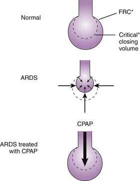
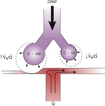
The primary effect of CPAP/PEEP is an increase in end-expiratory lung volume due to the increased Ptp. In lung diseases characterized by increased closing volume and decreased FRC, alveoli are unstable and tend to collapse. Recruitment of collapsed alveoli requires a Ptp greater than that required to sustain inflation once the alveoli are open. An increase in FRC above the closing volume restores this balance, prevents alveolar collapse, and maintains alveolar stability (Figure 49-12). This reduces the magnitude of V/Q mismatching because of improved distribution of alveolar ventilation.23,24 Airway closure and alveolar collapse can be prevented if the level of CPAP/PEEP is above the critical opening pressure. In lung disease with nonuniform or heterogeneous parenchymal involvement, CPAP/PEEP may hyperinflate normal lung segments, and this hyperinflation results in redistribution of blood toward the diseased segments, increasing intrapulmonary shunt on one hand and increasing alveolar dead space on the other (Figure 49-13).
Selection of Parameters for Mandatory Breaths
The first parameter is the tidal volume. A practical approach to determining an adequate tidal volume is to evaluate the desired degree of chest expansion during manual ventilation and to reproduce that when the patient is connected to the ventilator. A desirable VTeff for most patients is 8 to 10 mL/kg. Patients with normal lung compliance may require a preset tidal volume of 12 to 15 mL/kg to produce a VTeff of 8 to 10 mL/kg. Ideally, the end-inspiratory alveolar pressure should be less than 30 cm of H2O. The end-inspiratory alveolar pressure can be measured using an inspiratory hold maneuver. With an inspiratory hold, inspiratory flow is stopped, both inspiratory and expiratory valves are closed and the proximal airway pressure equilibrates with the alveolar pressure. The end-inspiratory hold pressure is called the pause pressure, plateau pressure, or simply end-inspiratory airway pressure. A large VTeff, especially those that results in an end-inspiratory airway pressure greater than 40 cm of H2O should be avoided. During mechanical ventilation, end-inspiratory alveolar pressure can be estimated through the measurement of the end-inspiratory airway pressure with an end-inspiratory hold maneuver.
PEEP is the next parameter to be selected. The level of PEEP will depend on the clinical circumstance. PEEP increases mean Paw during both volume-controlled and pressure-controlled ventilation, which results in a higher mean lung volume. The goals of PEEP are (1) increasing end-expiratory lung volume above closing volume to prevent alveolar collapse, (2) maintaining stability of alveolar segments, (3) improving oxygenation, and (4) reducing work of breathing. The optimum PEEP is the level at which there is an acceptable balance between the desired goals and undesired adverse effects. The desired goals are (1) reduction in inspired oxygen concentration to “nontoxic” levels (usually ≤50%); (2) maintenance of PaO2 or SaO2 (arterial oxygen saturation) of more than 60 mm Hg or more than 90%, respectively; (3) improvement of lung compliance; and (4) maximal oxygen delivery.25–27 Arbitrary limits cannot be placed on the level of PEEP or mean airway pressure that will be required to maintain adequate gas exchange. When the level of PEEP is high, peak inspiratory pressure may be limited to prevent it from reaching dangerous levels that contribute to air leaks and barotrauma.
Assisted Mechanical Ventilation
As defined previously, all assisted ventilation requires the patient to trigger the ventilator to provide a breath. With assisted ventilation, every breath that reaches a trigger threshold will result in a mechanical breath that is predetermined. There are two forms of assisted ventilation. The first kind of assisted breath is one where a mandatory breath is triggered by the patient’s effort. In this form of assisted breath, the breath is patient-triggered but machine cycled. The second kind of assisted breath is one where the breath is both patient-triggered and patient-cycled. The second kind of assisted breath is also classified as pressure control continuous spontaneous ventilation (PC-CSV) (see Table 49-1). There are various ways to assist spontaneous breaths with a PC-CSV breathing pattern. They include (1) pressure support: spontaneous breaths assisted with setpoint control; 2) volume assist: spontaneous breaths assisted with adaptive pressure control; (3) automatic tube compensation: spontaneous breaths assisted with servo control; (4) proportional assist ventilation: spontaneous breaths assisted with servo control; and (5) SmartCare: spontaneous breaths assisted with knowledge-based control.12,13 Following is a description of the most common mode of assisted ventilation that is used today.
Pressure-Support Ventilation
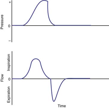
Pressure-support ventilation (PSV) is a form of assisted ventilation in which the ventilator assists the patient’s own spontaneous effort with a mechanical breath with a preset pressure limit. Figure 49-14 shows the important components of a pressure support breath. As with any form of support that is designed to respond to the patient’s effort, the inspiratory pressure assist of PSV requires a signal to trigger the demand valve to initiate flow.28 The patient’s spontaneous breath creates a negative pressure (pressure triggering) or a change in flow through the circuit (flow triggering), which triggers the ventilator to deliver a breath. With initiation, the machine delivers high inspiratory flow to achieve a peak airway pressure level that is selected by the operator.29–31 The pressure-limit stays constant as long as the patient’s inspiratory effort is maintained with a variable gas flow rate from the ventilator.30,31 As inspiration continues, the inspiratory flow rate decreases. A threshold reduction in the flow rate is a signal for the termination of the inspiratory assist, with the opening of an expiratory valve, after which passive exhalation occurs.29–31 The termination signal can be a predetermined percentage of the peak inspiratory flow (10% or 25%) or a fixed flow (usually 5 L/min).32–34 Many ventilators also incorporate backup flow termination criteria, such as the duration of inspiration greater than 5 seconds or an increase in the airway pressure above the set pressure support level (e.g., when a patient attempts to cough). In summary, PSV is patient triggered, pressure limited, and flow cycled. PSV is entirely dependent on the patient’s effort; if the patient becomes apneic, the ventilator will not provide any mechanical breath.
Other Modes of Ventilation
Airway Pressure Release Ventilation
Airway pressure release ventilation (APRV) is a method of mechanical ventilation introduced by Stock and Downs.35,36 It was based on the premise that most patients with acute lung injury (ALI) or adult respiratory distress syndrome (ARDS) required positive pressure support to maintain an adequate lung volume and required minimal, if any, ventilatory assistance.35,36 These authors theorized that if a sufficiently high level of CPAP were provided with a high gas flow rate, it would maintain an adequate lung volume and oxygenation while ventilatory needs would be met entirely by spontaneous breathing. If ventilatory assistance were to be required, CPAP level could be abruptly reduced for a short period of time and this could be repeated several times in a minute to enhance ventilation. So, the original circuit included a CPAP device and a mechanism to release airway pressure periodically to some desired low pressure. Simplistically, this can be thought of as pressure-limited, time-cycled ventilation, in which the preset pressure limit is equal to the level of CPAP required and the PEEP is usually ambient pressure or a selected lower airway pressure, with reversal of I/E ratio. Spontaneous breathing occurs at both levels of airway pressure. In the original description, the gas flow through the circuit was continuous and allowed unrestricted spontaneous breathing. It was recommended that the flow rate be kept slightly above the peak inspiratory flow rate of a spontaneous breath. Minute ventilation occurs with both spontaneous breaths and the periodic inflation and deflation that occur with the two levels of airway pressure. Gas exchange can occur throughout the respiratory cycle. Several studies with acute respiratory failure have shown that APRV results in improvement in gas exchange with much lower airway pressures.35,37–39 Lower peak airway pressures are the consistent major advantage of ARPV. Because airway pressures are lower, APRV results in less adverse cardiovascular effects than IMV, when both are added to CPAP.37,39 Some of the modern ventilators have incorporated features that allow spontaneous breathing through a demand-flow system during both the inspiratory and expiratory phases of a pressure-controlled, time-cycled breath. These are called by different names such as biphasic positive airway pressure and intermittent mandatory pressure-release ventilation. These different modes have been classified under the acronym APRV. Some ventilators incorporate pressure-support to be provided for the spontaneous breaths during these modes. It is clear that the patient-ventilator interactions are clearly different between the original APRV circuit and the modern APRV systems. Generally, demand-flow systems increase the trigger work of breathing and therefore are not necessarily unrestricted, especially in infants and children. At the present time, not enough information is available in infants and children.
Mandatory Minute Volume Ventilation
Mandatory minute volume ventilation (MMV) was first introduced by Hewlett et al.40 in 1977. In this mode, the patient is guaranteed a preset delivered minute ventilation. If the spontaneous minute ventilation exceeds the preset value, then the ventilator reduces the rate to zero and does not deliver a mechanical breath. If there is no spontaneous minute ventilation, then the ventilator will deliver sufficient breaths to match the preset minute ventilation. If the spontaneous minute ventilation is insufficient to match the preset value, then the ventilator will provide the remainder of the minute ventilation. Different mechanisms are used by manufacturers to achieve this goal. In the Ohmeda CPU1 ventilator, the preset minute ventilation is compared with the patient’s total minute ventilation (spontaneous and mechanical) every 24 cycles and then adjusted. In the Engstrom Erica ventilator, it is done on a breath-by-breath basis. Currently, there is not much experience with MMV in pediatric patients. The indications of MMV are in patients after abdominal surgery, especially with complications; patients who are recovering from respiratory muscle paralysis (e.g., Guillain-Barré syndrome, myositis, myasthenia gravis); and patients who have widely fluctuating respiratory drive (encephalopathy).
Dual Control Modes
Dual Control Within a Breath
These modes allow the ventilator to deliver a pressure-controlled breath or switch from a pressure-controlled breath to a volume-controlled breath within the breath. This is shown in Figure 49-15. This mode is referred to as VAPS (Bird 8400ST and Tbird, Bird Corp., Palm Springs, Calif.) and pressure augmentation (PA) (Bear 1000). Both of these techniques can operate during mandatory breaths (pressure limited, time cycled) or pressure-supported breaths. During VAPS and PA, the clinician must set the respiratory frequency, peak flow, PEEP, inspired oxygen concentration, trigger sensitivity, and minimum desired tidal volume. During VAPS or PA, the ventilator’s inspiratory flow waveform is constant (square). Additionally, the pressure support setting must be set. During pressure support, VAPS and PA can be considered a safety net that always supplies a minimum tidal volume. A VAPS or PA breath may be initiated by the patient or time triggered. After the breath is triggered, the ventilator attempts to reach the pressure support setting as quickly as possible. This portion of the breath is the pressure control portion and is associated with a rapid variable flow, which may reduce the work of breathing. As this pressure level is reached, the ventilator’s microprocessor determines the volume that has been delivered from the machine (note: this is not exhaled tidal volume), compares this measurement with the desired tidal volume, and determines whether the minimum desired tidal volume will be reached. If the ventilator determines that the ultimate delivered tidal volume will be equivalent to the set tidal volume, the breath is delivered as a pressure support breath. If the ventilator determines that the ultimate delivered tidal volume will be less than the set tidal volume, then the breath changes from a pressure-limited to a volume-limited breath. At that point, inspiratory flow remains constant and the ventilator increases the inspiratory time until the desired volume has been delivered. Inspiratory pressure will increase above the set pressure support setting. Setting the high-pressure alarm remains important during VAPS. If pressure increases abruptly, the high-pressure alarm setting is reached, and the breath is pressure cycled (see Figure 49-15). VAPS breath can allow the patient a tidal volume larger than the set volume.
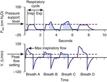
Figure 49–15 Pressure and flow waveforms illustrating VAPS.
(From Branson RD, MacIntyre NR: Dual-control modes of mechanical ventilation, Respir Care 41:294–305, 1996.)


Stay updated, free articles. Join our Telegram channel

Full access? Get Clinical Tree


