57 Imaging of the Chest
 Principles of Imaging in the Intensive Care Unit
Portable chest radiography plays a major role in patient care, especially in critically ill patients. Bedside chest radiographs are frequently obtained in ICU patients, and an understanding of how to interpret these films is important for ICU physicians. The American College of Radiology’s current guidelines call for daily chest radiographs of all mechanically ventilated patients in the ICU,1 but this approach is controversial. Some earlier studies supported this recommendation, arguing that early detection of unexpected findings on routine films may save money and decrease length of stay.2–4 However, several recent and larger studies have refuted this, demonstrating that a small minority of routine chest radiographs have any significant impact on patient management. Further, these studies suggest that transition to on-demand imaging saves money and radiation exposure without prolonging length of stay or negatively impacting other safety parameters.5–10
 Conventional and Digital Radiography
With conventional portable radiography units, the maximum tube current and voltage are limited, so exposure times are relatively long, and image contrast may be excessive. Digital (or computed) radiography uses a phosphor plate in lieu of a film-screen combination to capture and store the radiographic image, which reduces the patient’s radiation dose. When digital images are processed, the portion of the dynamic range containing the diagnostic information is identified, and the final output for display is adjusted to a consistent and optimized contrast and density. This obviates the need for repeated examinations because of errors in exposure and may improve diagnostic yield.11 For these reasons, as well as the ease with which digital processing allows placement of images on a digital network, digital radiography has largely replaced conventional techniques.
Conventional and digital radiography share some disadvantages, however. The overall time required for obtaining the radiograph remains the same, and both portable techniques capture images in the anteroposterior projection. When combined with a shorter source image receptor distance, this leads to geometric magnification of anterior chest structures such as the heart. In addition, severe patient illness in the ICU often requires supine and semi-upright positioning, which may complicate interpretation of radiographs, particularly in cases of pneumothorax or pleural effusion.12
 Computed Tomography
Computed tomography provides better anatomic detail and a higher degree of diagnostic accuracy than chest radiography, but for critically ill patients, transportation and cumbersome monitoring devices limit access to CT. Mobile CT scanners have been developed to image critically ill patients in the ICU and avoid the need for transportation. They are not yet in widespread use, in part due to image quality concerns, but have demonstrated utility in neurosurgical13–16 and other intensive care applications,17 including infectious disease outbreak situations.18
 Picture Archiving and Communications System
 Interpreting the ICU Chest Radiograph
Monitoring and Support Devices
Endotracheal Tubes
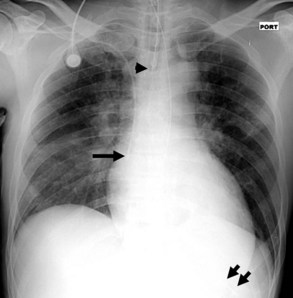
On the chest radiograph, the position of an endotracheal tube (ETT) is determined by the location of the tube’s tip in relation to the carina with respect to the position of the patient’s chin. With the chin in the neutral position, the tip of the ETT should be 3 to 7 cm above the carina (Figure 57-1). Alternatively, the tip of the ETT should project over the T3 or T4 vertebral body, because the carina is located between T5 and T7 on anteroposterior radiographs in most individuals. Neck flexion and extension can result in 2 cm of downward or upward displacement, respectively, of the ETT.19 Projection of the anterior portion of the mandible over the lower cervical spine indicates neck flexion, whereas an unobscured cervical spine indicates neck extension.
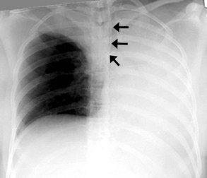
The most common complication of ETT placement is inadvertent intubation of the right main bronchus (Figure 57-2) because of its shallower angle of departure from the trachea compared to the left main bronchus. Esophageal placement of the ETT can occur, although this is usually detected on physical examination. Radiographic findings of esophageal intubation include direct visualization of the ETT lateral to the tracheal wall, gaseous distention of the stomach, and displacement of the trachea by an overdistended balloon cuff.
Tracheostomy Tubes
The tip of a tracheostomy tube should be several centimeters above the carina, and the tube’s diameter should be approximately two-thirds that of the trachea.20 Unlike ETTs, chin position does not affect tracheostomy tube position. Air is commonly seen in the subcutaneous tissue of the neck and upper mediastinum immediately after tracheostomy tube placement and should resolve over time. Pneumothorax and mediastinal hematoma, the latter manifesting as a dense mediastinum with full, convex margins, are more worrisome complications of tracheostomy tube placement that should not be overlooked.
Central Venous Catheters
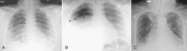
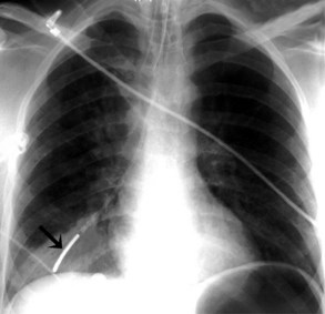
Central venous catheters are inserted from an internal jugular (IJ), subclavian (SC), or femoral approach. The optimal location of an IJ or SC catheter tip is within the superior vena cava downstream of the central venous valves. On the anteroposterior chest radiograph, the origin of the superior vena cava usually lies to the right of midline at the level of the first intercostal space (see Figure 57-1).21 The catheter tip should remain proximal to the right atrium to reduce the risk of arrhythmias, myocardial perforation, or cardiac tamponade. Portable chest radiographs should be obtained immediately after central venous catheter placement to determine catheter position and identify any complications such as pneumothorax, vessel perforation (Figure 57-3), cardiac perforation, retained or fragmented catheter, or a knotted catheter.
Peripherally Inserted Central Catheters
Peripherally inserted central catheters (PICCs) are relatively new devices gaining widespread acceptance for long-term central venous access. The catheters are small, 2 to 5 French, and are placed into the superior vena cava through a large upper-extremity vein. PICCs may be difficult to identify on bedside chest radiographs because of their small size and faint opacity. They are also more susceptible to displacement than other intravenous catheters, owing to increased flexibility of the material (see Figure 57-3).
Pulmonary Artery Catheters
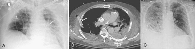
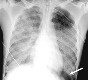
Pulmonary artery catheters measure intracardiac and intrapulmonary pressures reflecting volume status, cardiac function, and vascular tone. Their use is declining in many ICUs because recent studies demonstrate limited utility in affecting patient outcomes in a variety of clinical settings.22,23 Nevertheless, when they are used, accurate placement is critical for proper interpretation. The catheters are usually introduced via an internal jugular or subclavian approach; less commonly they may be inserted through the femoral vein. They then traverse the central venous system into the right ventricle, through the pulmonic valve into the main, then right (less commonly left) pulmonary artery, then “wedge” in a proximal interlobar artery. If the tip extends beyond these larger arteries (Figure 57-4), pulmonary infarction from occlusion of the pulmonary vessel or development of a pseudoaneurysm can ensue. The balloon at the catheter tip should be inflated only during placement or when obtaining pressure measurements, so an inflated balloon should never be present on a portable chest radiograph. Complications are similar to those that occur with other central venous catheters but also include pulmonary vascular perforation and pulmonary hemorrhage.
Thoracostomy Tubes
Thoracostomy tubes are placed in the pleural space to drain fluid or air. On a chest radiograph, the side port of a thoracostomy tube is marked by a disruption in the radiographically opaque line and should be located medial to the inner margin of the ribs. A malpositioned thoracostomy tube is often suspected when the tube does not drain as expected. It may not be inserted into the pleural space at all but instead tunnel through the subcutaneous soft tissues. Alternatively, the tip may lie within a pulmonary fissure, or rarely within the lung parenchyma. Subcutaneous placement can be very difficult to ascertain on chest radiograph, and an intrafissural location can only be suspected when the tube follows the course of one of the pulmonary fissures. The cross-sectional nature of CT scans provides an advantage to accurately identify the course of a thoracostomy tube and its relationship to abnormal air or fluid collections (Figure 57-5).
Enteric Tubes
Enteric tubes are placed into the stomach or proximal small bowel via a transoral or transnasal approach and come in a variety of sizes and configurations (see Figure 57-1). These tubes are frequently placed in ICU patients, especially those who are endotracheally intubated. Although the best position for feeding tubes is controversial, placement distal to the pylorus may decrease the risk of aspiration.24 Usually, enteric tube position is easily determined by a chest or abdominal radiograph, although they may occasionally be obscured by excess soft tissue in obese patients. These tubes can coil in the pharynx or esophagus, putting the patient at risk for aspiration if tube feeds are initiated. Inadvertent insertion into the tracheobronchial tree (Figure 57-6) and esophageal perforation are rare but have more serious consequences.
 Approach to ICU Chest Imaging
 Lung Abnormalities
Diffuse Lung Opacities
Cardiogenic Pulmonary Edema
Several conditions can cause the pattern of homogenous lung opacity that represents, or mimics, pulmonary edema. The classic appearance of cardiogenic pulmonary edema is that of bilateral perihilar fluffy opacities, sometimes called a butterfly or bat-wing pattern, in association with an enlarged heart, engorgement of central pulmonary veins, interstitial edema, and vascular redistribution or cephalization of vessels (Figure 57-7). Pleural effusions may also be present. The opacities associated with cardiogenic pulmonary edema can fluctuate rapidly, a clue to its diagnosis. However, this classic appearance is rare in the ICU. The bat-wing pattern is seen in few patients with pulmonary edema; opacities may be asymmetrical due to variations in patient position and underlying cardiopulmonary disease, such as emphysema or mitral valve insufficiency. In addition, cephalization of the vasculature is not a very useful marker of edema in supine ICU patients. Finally, some patients, particularly those with milder disease or chronically elevated left ventricular pressures, may only have more subtle radiographic findings, such as peribronchial cuffing and indistinct vessels.25,26 Serial measurements of vascular pedicle width may be a useful adjunct indication of intravascular volume status in these patients.27
Neurogenic Pulmonary Edema
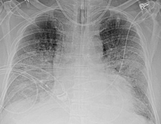
Neurogenic pulmonary edema can occur in the setting of any cerebral insult, including intracranial hemorrhage or mass, head trauma, stroke, seizures, or infection. Elevated microvascular pressure and increased vascular permeability in the lung both appear to play a role in its development.28 Neurogenic pulmonary edema can develop within hours after the neurologic insult or several days later. On the chest radiograph, neurogenic edema usually manifests as a diffuse, homogeneous pulmonary opacity similar to that of cardiogenic edema, but without an enlarged cardiac silhouette and often without the indistinct vessels that suggest engorgement. (Figure 57-8). Occasionally, opacities may have a focal distribution reflecting gravity, patient position, and heterogeneity in pulmonary venous pressure. Rapid clearing of the lungs within days of resolution of the neurologic insult is characteristic, in contrast to other forms of noncardiogenic pulmonary edema in which opacity can persist.28 It is important to note that some patients with neurologic injury are treated with large volumes of intravenous fluid, which may complicate the interpretation of pulmonary edema opacities on the chest radiograph.
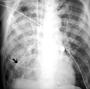
Acute Lung Injury and Acute Respiratory Distress Syndrome
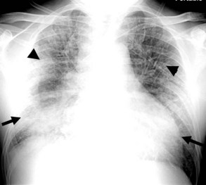
Acute lung injury (ALI) and acute respiratory distress syndrome (ARDS) are common in medical and surgical ICU patients and have a high mortality.29–31 They are clinical syndromes defined by hypoxemia and diffuse bilateral lung opacities in the absence of left atrial hypertension.32 Both result from a massive inflammatory reaction in the lungs incited by a variety of causes, and they are radiographically indistinguishable. The severity of hypoxemia alone differentiates the two, with ARDS the more severe manifestation. In the acute phase of ARDS, diffuse ill-defined opacities often predominate in the periphery of the lungs. As the disease progresses, the entire hemithorax can become opacified on chest radiographs (Figure 57-9), although CT typically demonstrates heterogeneity in lung aeration. This finding has led to much discussion regarding appropriate ventilator management of ARDS to balance alveolar recruitment while avoiding hyperinflation of spared lung tissue (see Chapter 58). During the subacute phase (5 to 10 days later), proliferation of endothelial cells and fibroblasts leads to a pattern of progressive lung destruction. Some patients recover from ARDS without any residual deficit in pulmonary function, but others progress to a chronic phase several weeks after the initial lung injury and have permanent respiratory sequelae. Fibrosis and focal emphysema are usually evident on these patients’ radiographs or CT scans.


Stay updated, free articles. Join our Telegram channel

Full access? Get Clinical Tree


