INTRODUCTION
EMERGENCY ULTRASOUND: INTRODUCTION
Emergency ultrasound (EUS) is the use of point-of-care ultrasound by clinicians in the emergency department (ED) to answer focused clinical questions and/or assist in performing invasive procedures. It is not an extension of the physical exam by means of advanced technology, but rather uses ultrasound technology to sonographically assess patients for the presence or absence of pathologic conditions that commonly present to the ED. The use and scope of EUS has grown and evolved since the FAST exam was first introduced as part of the evaluation of the trauma patient. For more than a decade, EUS has been a required component of Emergency Medicine Residency training with additional training offered as part of a dedicated EUS fellowship programs. These dedicated EUS fellowship training programs have surged in recent years to meet the demand, with over 90 such programs currently operating.
EUS can be used by clinicians across the spectrum of diseases that present to the ED. Properly trained emergency clinicians use ultrasound to answer focused questions regarding the patient’s presenting complaint or condition. Rather than a comprehensive approach, the EUS examination is goal-directed and focused, often seeking to answer dichotomous, “yes/no,” questions such as “Is there fluid within the peritoneum?”
This text is not intended to provide an in-depth description of the limitations, efficacy, sensitivity, or appropriateness of EUS. Every application described herein is intended as a rapid visual review for those trained in basic EUS applications. Applicable protocols are based on the imaging guidelines of the American College of Emergency Physicians and American Institute of Ultrasound in Medicine (AIUM), as well as the authors’ collective experience. Basic information—transducer recommendations, scanning protocols, anatomic schematics—is presented within each application to represent both image acquisition and normal and pathological findings.
Sonographic windows—Anatomical locations on the body where an ultrasound probe is placed in order to view internal organs.
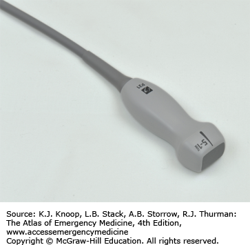
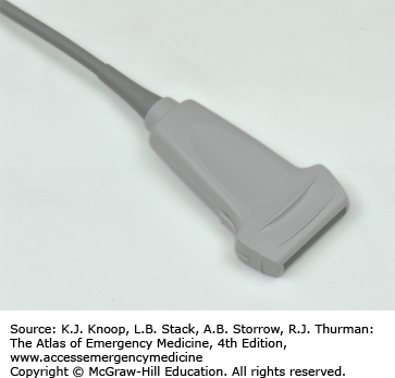
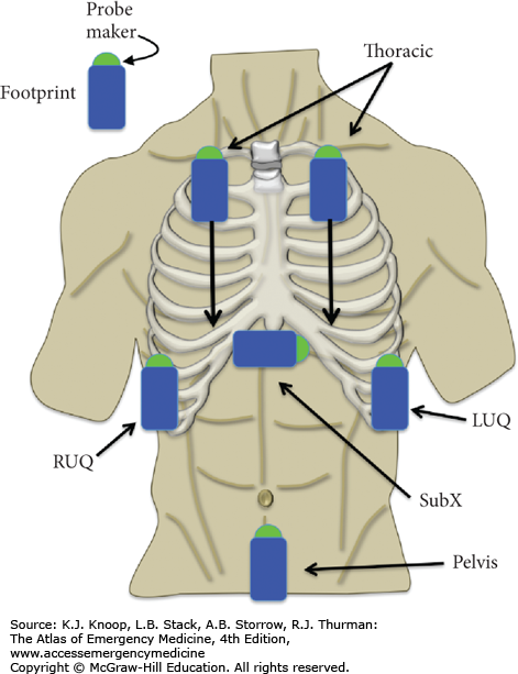
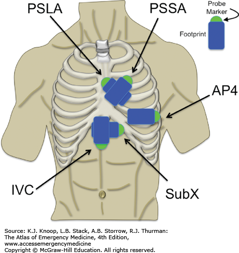
Transducer indicator/probe marker/marker dot—Usually a bump or ridge on the ultrasound transducer that corresponds to a symbol on the ultrasound screen. Used to indicate which side of the image corresponds with the transducer’s edge (Fig. 24.1).
Foot print—The part of the ultrasound probe that contacts the patient’s skin (Fig. 24.1).
Hyperechoic/echogenic—Used to describe objects on the ultrasound screen that are bright and therefore reflect sound waves.
Hypoechoic/anechoic—Used to describe objects on the ultrasound screen that are dark and therefore transmit sound waves.
Echotexture—The characteristic appearance of specific organs when viewed using ultrasound. The liver has a characteristic echotexture.
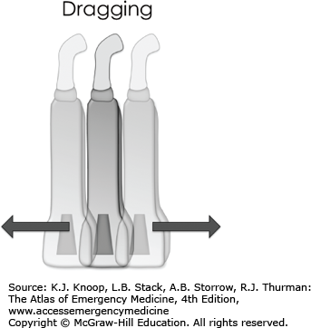
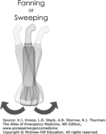
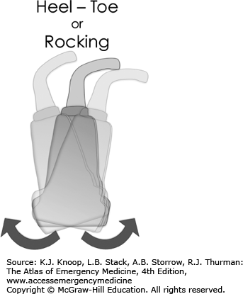
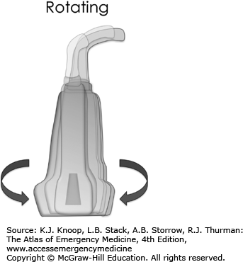
Transducer movements—When performing sonography, specific terms are used to describe characteristic movements of the transducer used to obtain the image desired. Some examples of this include dragging, rocking, fanning, and rotating (Fig. 24.2).

Emergency sonography is performed using a wide variety of transducers. Lower frequency transducers are used to visualize structures deep within the body, while higher frequency transducers allow better image resolution of superficial anatomic structures. The size and shape of transducers are also configured for imaging specific anatomic locations. Table 24.1 lists the basic transducer types frequently used in EUS.
| Transducer | Image Appearance | Applications* |
|---|---|---|
Phased array
FIGURE 24.3a
| Cardiac
FIGURE 24.3b Abdominal
FIGURE 24.3c | (+) Cardiac, abdominal, thoracic (−) Soft tissue, pregnancy, vascular |
Linear array
FIGURE 24.4a
|
FIGURE 24.4b | (+) Procedural, vascular, soft tissue/MSK, superficial, thoracic (pleural), ocular (−) Abdominal, cardiac, pregnancy |
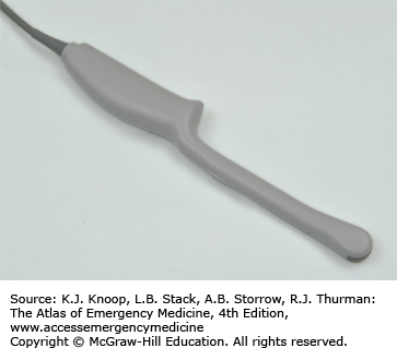
Endocavitary probe
FIGURE 24.5a
|
FIGURE 24.5b | (+) Transvaginal pregnancy, intraoral (−) Any external exam |
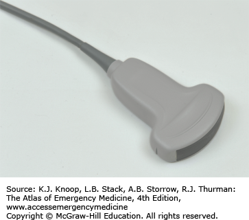
Curvilinear/convex array transducer
FIGURE 24.6a
|
FIGURE 24.6b | (+) Aorta, abdominal, transabdominal pregnancy (−) Cardiac |


TRAUMA ULTRASOUND
The Extended Focused Assessment with Sonography in Trauma (E-FAST) is a protocolized series of sonographic views that attempt to identify the presence or absence of fluid or air in anatomic potential spaces such as the pericardium, the peritoneum, and the thorax. The goal of this thoracoabdominal survey is to identify or exclude immediate life threats in the trauma or critically ill patient. Though initially intended for the evaluation of the trauma patient, the E-FAST examination and its component views are also extremely valuable in the evaluation of several emergent complaints and clinical conditions including the patient with undifferentiated hypotension.
Trauma (blunt and penetrating)
Unexplained hypotension (traumatic and nontraumatic)
Ectopic pregnancy (to evaluate for rupture)
The FAST examination uses four primary sonographic views to evaluate the patient. It is recommended that all four views are evaluated for a complete exam, but isolated views may be obtained when indicated. The extended component of the FAST exam (termed E-FAST) incorporates imaging of both the anterior and lateral hemithoraces to identify the presence or absence of a pneumothorax or hemothorax (Fig. 24.7). It is important to note that these are not static “single” views, but a series of images obtained in each plane as the transducer is moved or “fanned” through the area of interest.
Pericardial (usually a subcostal/subxiphoid view—alternatively, one may obtain a parasternal long view of the heart if a subxiphoid view is unobtainable)
Right upper quadrant (RUQ; pouch of Morison)
Left upper quadrant (LUQ) (perisplenic view)
Suprapubic (pelvic view)
Right thorax
Left thorax
The E-FAST exam should be done with the patient in the supine position.
Convex array (abdominal, cardiac, and lung imaging)
Phased array (abdominal, cardiac, and lung imaging)
Linear array (lung only)
The E-FAST examination is a thoracoabdominal examination. Ideally, this is done using a single transducer that can image all three of these areas, but may result in some compromise of image quality and require the use of different probes for different components of the examination.
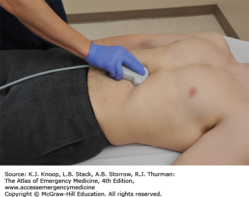
PERICARDIAL (SUBXIPHOID VIEW)
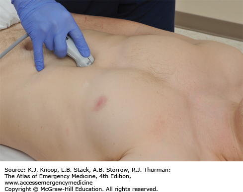
Direct the transducer indicator to the patient’s right (in abdominal or general preset). Note that the E-FAST exam is traditionally performed with abdominal preset settings, but the subxiphoid view is often performed with cardiac preset settings as part of a full focused cardiac ultrasound exam. When this is the case, the marker dot is typically on the opposite side of the screen and the indicator is oriented to the patient’s left.
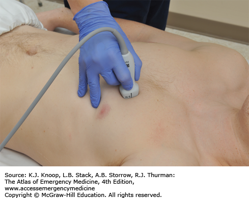
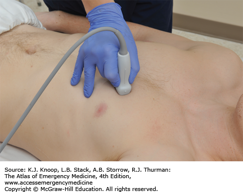
With the transducer indicator pointing to the patient’s right, the transducer is directed under the xiphoid process toward the left shoulder in a horizontal plane (Fig. 24.8).
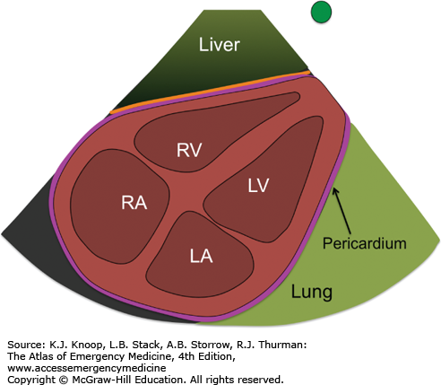
Pivot, sweep, and tilt the transducer as necessary to view all four cardiac chambers and pericardium.
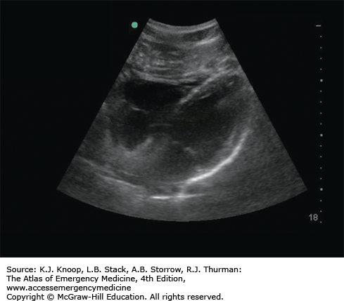
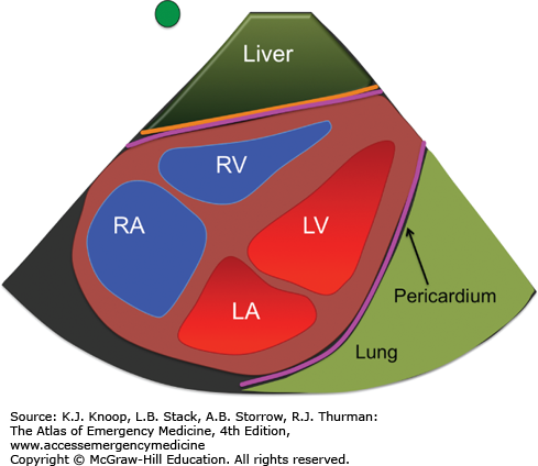
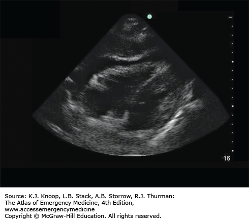
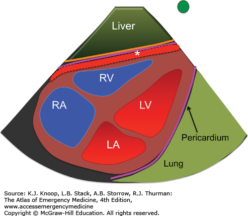
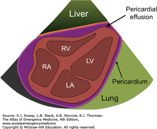
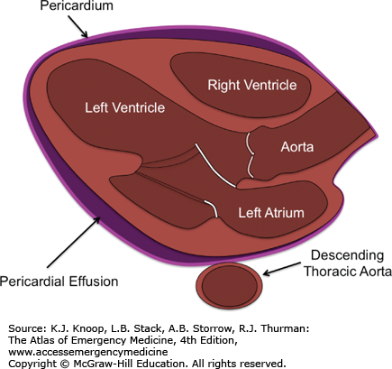
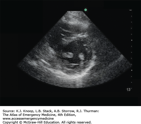
Identify the liver (if in view), heart, four cardiac chambers, and surrounding pericardium (Fig. 24.9).
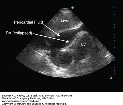
Hemopericardium (pericardial effusion): Pericardial fluid will appear as an anechoic (black) region noted between the pericardium and the right ventricle. As more fluid collects, the fluid will be seen completely surrounding all four chambers of the heart. Occasionally, internal echoes representing fibrin, clot, or cardiac tissue may be present within the pericardial space (Fig. 24.10).
Asystole: No cardiac activity present.
Hyperdynamic cardiac activity: Extensive cardiac contraction with near-total or complete collapse of the cardiac chambers, often associated with tachycardia and hypovolemia.
When the view is obscured by gas, slide the transducer slightly to the patient’s right subcostal region, and use the right lobe of the liver as the sonographic window.
If unable to view the heart in the true subxiphoid or subcostal window, move to a parasternal long-axis view (see “Focused Cardiac Ultrasound” below).
A frequent mistake in imaging is to direct the transducer posterior toward the spine rather than cephalad toward the shoulder. You will often require less than a 30-degree angle between the transducer and the skin to view the heart.
Start imaging with the depth/scale setting near its maximum (eg, 24-35 cm). This should allow you to image the anterior and posterior pericardium in your initial view. Gradually decrease the depth/scale (eg, 14-18 cm) to fill the entire sector image with the heart as you continue to optimize your image.
Hypotensive trauma patients with a pericardial effusion and findings such as right ventricular (RV) collapse and/or a distended inferior vena cava (IVC) warrant emergent pericardiocentesis (see Fig. 24.34).
RIGHT UPPER QUADRANT (POUCH OF MORISON)
With the indicator directed toward the patient’s head, the transducer is oriented in a coronal section through the body in the midaxillary line, extending from the 9th through 12th ribs. Start between the 11th and 12th ribs initially, then move cephalad or caudal, anterior or posterior, to complete the evaluation (Fig. 24.11).
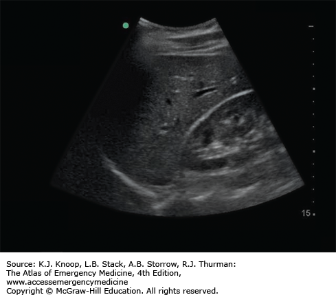
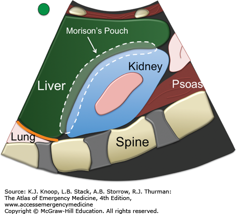
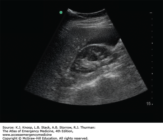
Identify and evaluate the interface of the liver and right kidney. This region is the potential space known as the pouch of Morison. Normally, the liver and kidney are in direct contact with one another or separated by adipose tissue of heterogeneous echoes (Fig. 24.12).
Evaluate the right paracolic gutter by identifying and evaluating the caudalmost portion of the hepatic parenchyma (inferior tip of the liver).
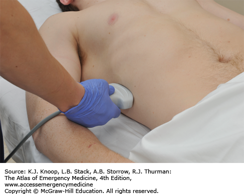
FIGURE 24.12
Normal Right Upper Quadrant View (Morison Pouch). Identify and evaluate the interface of the liver and right kidney. This region is the potential space known as the pouch of Morison. Normally, the liver and kidney are in direct contact with one another or separated by adipose tissue of heterogeneous echoes. The reflection of the anterior border of the lumbar spine is visualized deep to the kidney and terminates at the costophrenic angle in the absence of fluid within the thoracic cavity. (Ultrasound contributor: Jeremy S. Boyd, MD; illustration courtesy of Robinson M. Ferre, MD.)
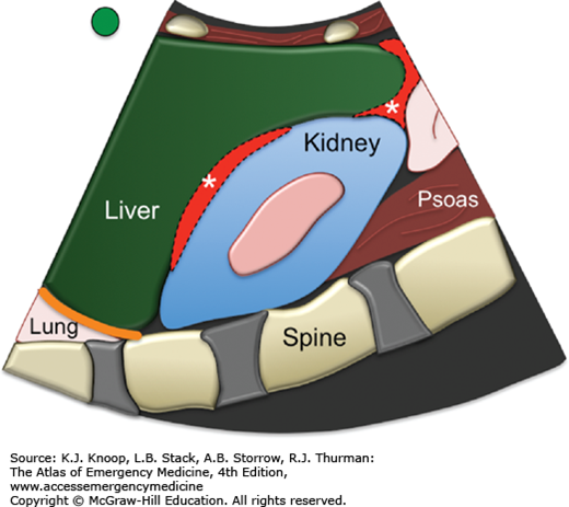
Hemoperitoneum: Anechoic (black) region between the liver and right kidney or in the paracolic gutter. Rarely is blood only seen collecting between the diaphragm and the liver in the subdiaphragmatic space (Fig. 24.13).
Solid organ injury: Solid organ injury such as hepatic and renal lacerations as well as organ rupture have been described but are not the goal of this examination as ultrasound is an insensitive exam for solid organ injury.
FIGURE 24.13
Hemoperitoneum (Right Upper Quadrant view). An anechoic (black) region between the liver and right kidney is fluid (blood in this case) accumulating within the potential space. The diagram illustrates the typical locations of these peritoneal potential spaces, marked by asterisks. (Ultrasound contributor: Jeremy S. Boyd, MD; illustration courtesy of Robinson M. Ferre, MD.)
LEFT UPPER QUADRANT (PERISPLENIC VIEW)
The transducer indicator is directed toward the axilla.
With the indicator pointed toward the patients head, the transducer is oriented in a coronal section through the body in the mid to posterior axillary line extending from the 9th through 12th ribs. Start between the 11th and 12th ribs initially, then move cephalad or caudal, anterior or posterior, to complete the evaluation (Fig. 24.14). As a general rule of thumb, the perisplenic view is more poseterior and cephalad than that of the RUQ view.
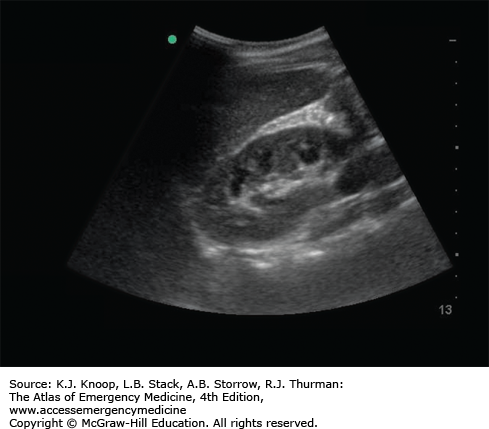
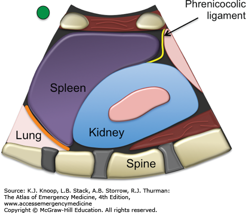
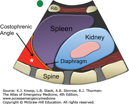
Identify and evaluate the area surrounding the spleen, including its upper and lower poles, the interface with the diaphragm, and the interface with the left kidney. Normally, the surrounding tissues of the spleen and kidney are in direct contact with one another (Fig. 24.15).
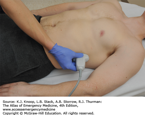
FIGURE 24.15
Normal Left Upper Quadrant View. The region between the spleen and left kidney is a physiologic potential space (splenorenal recess); however, due to the phrenicocolic ligament (rarely seen on ultrasound but shown on illustration), free fluid is often shunted toward the subdiaphragmatic space between the diaphragm (orange line) and spleen. (Ultrasound contributor: Jeremy S. Boyd, MD; illustration courtesy of Robinson M. Ferre, MD.)
Hemoperitoneum: Anechoic (black) region around the spleen. This may be visible at the superior or inferior poles of the spleen, between the spleen and the diaphragm or between the spleen and left kidney. Unlike the pouch of Morison, blood cannot flow beyond the inferior pole of the spleen down the paracolic gutter due to the phrenicocolic ligament. Blood that collects in the perisplenic space must first pass out of the lesser peritoneal sac and into the greater peritoneal sac before it will be seen collecting along the left paracolic gutter (Fig. 24.16).
Solid organ injury: Solid organ injury such as splenic and renal lacerations as well as organ rupture have been described but are not the goal of this examination as ultrasound is an insensitive exam for solid organ injury.
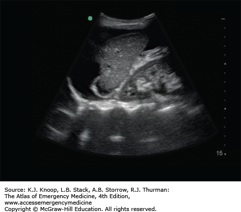
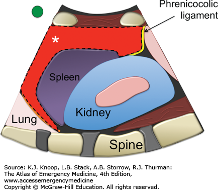
FIGURE 24.16
Hemoperitoneum, Left Upper Quadrant View. In this view, fluid is seen in the subdiaphragmatic space between the diaphragm and the spleen. The diagram illustrates other common potential sites for free fluid, marked by asterisks. (Ultrasound contributor: Jeremy S. Boyd, MD; illustration courtesy of Robinson M. Ferre, MD.)
The diaphragmatic recess includes a superior region, which is the inferior border of the right thorax (often referred to as the costophrenic angle), and an inferior region (subdiaphragmatic recess), which is the superior border of the abdomen. Fluid in the diaphragmatic recess can represent a hemothorax when located superior/cephalad to the diaphragm or a hemoperitoneum (inferior to the diaphragm) in the setting of trauma.
If you are uncertain whether a finding is real or artifact, evaluate it in a second plane. Turn the transducer 90 degrees from your initial transducer position to see if the finding is still noted on the image. If the entire image is unchanged, it is less likely to be an artifact.
The liver is affixed to the diaphragm via the coronary ligament but the spleen lacks a similar attachment. Dependent fluid collects in the left subdiaphragmatic area more often than the right and this space should be evaluated sonographically during the examination.
SUPRAPUBIC
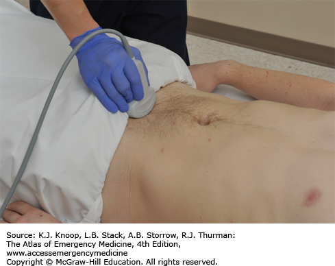
With the indicator oriented toward the patient’s head, the transducer is placed just above the symphysis pubis and is directed into the pelvis (Fig. 24.17).
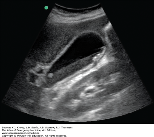
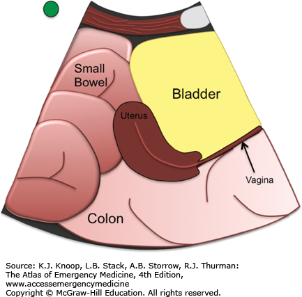
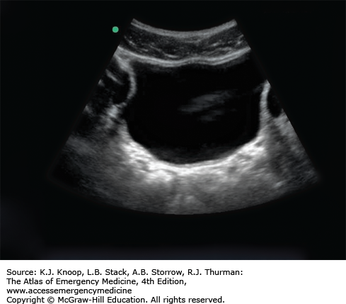
Identify the bladder (triangular in this view when fully distended), uterus (pear-shaped if present), prostate, seminal vesicles, and rectum (Figs. 24.18 and 24.19).
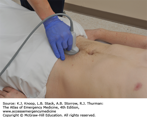
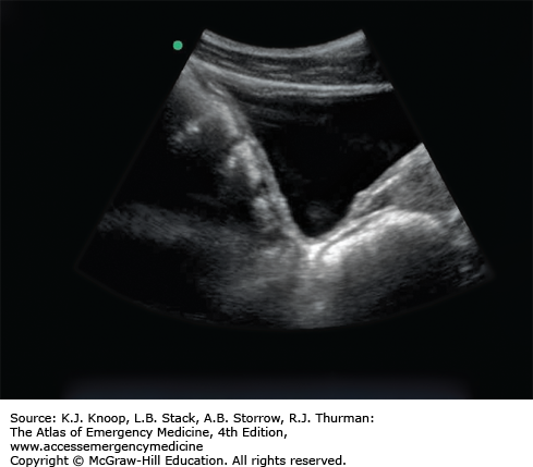
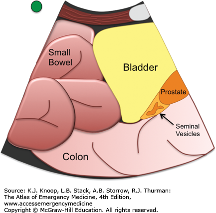
FIGURE 24.19
Normal Female Pelvis, Sagittal View. The uterus appears pear-shaped in this view, and may be anteroflexed or retroflexed. The “pouch of Douglas” is a potential space between the uterus and the rectum, and is deep to the uterus. (Illustration courtesy of Robinson M. Ferre, MD; ultrasound contributor: Jeremy S. Boyd, MD.)
With the indicator oriented toward the patient’s right, the transducer is placed about 1 to 2 cm above the symphysis pubis and the beam is angled through the bladder into the peritoneum (Fig. 24.20).
Identify the bladder (rectangular in this view when fully distended), uterus (oval hyperechoic structure if present), prostate, seminal vesicles, and rectum (Fig. 24.21).
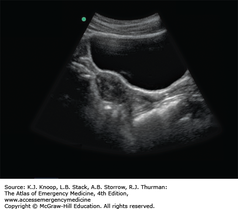
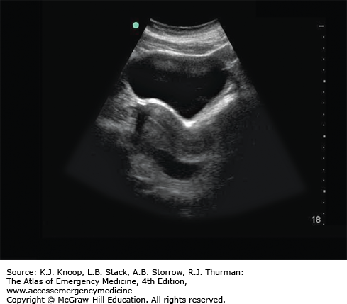
Hemoperitoneum (male pelvis): Free fluid in the male pelvis is seen as anechoic (black) areas filling the rectovesicular space, the potential space between the bladder and the rectum. The rectovesicular space is immediately cephalad to the extraperitoneal prostate and seminal vesicles. In the sagittal view, it is easier to see this junction that distinguishes the peritoneal cavity from the extraperitoneal pelvis. A large amount of free fluid may appear as loops of bowel floating lateral to the bladder in the transverse view and superior to the bladder in the sagittal view (Figs. 24.22 and 24.24).
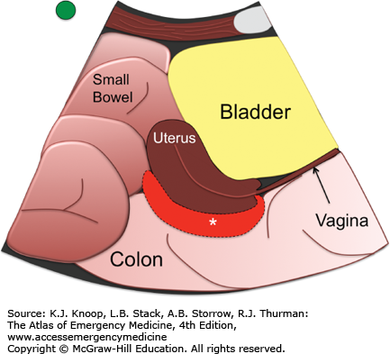
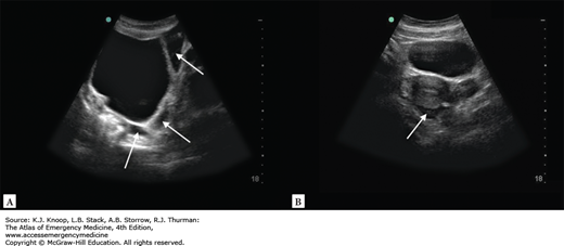
Hemoperitoneum (female pelvis): Free fluid in the female pelvis is seen as an anechoic (black) area in the rectouterine space, the potential space between the uterus and rectum. The vaginal stripe is an extraperitoneal structure and intraperitoneal fluid will not be seen collecting beneath it. A large amount of free fluid may appear as loops of bowel floating lateral to the bladder in the transverse view and superior to the bladder in the sagittal view (Figs. 24.23 and 24.24).
FIGURE 24.22
Hemoperitoneum, Sagittal Male. Hemoperitoneum is seen deep to the bladder in the rectovesicular area on this sagittal view (arrow). Free fluid is seen as an anechoic (black) area in the rectovesicular space as demarcated by the asterisk. (Illustration courtesy of Robinson M. Ferre, MD; ultrasound contributor: Jeremy S. Boyd, MD.)
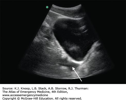
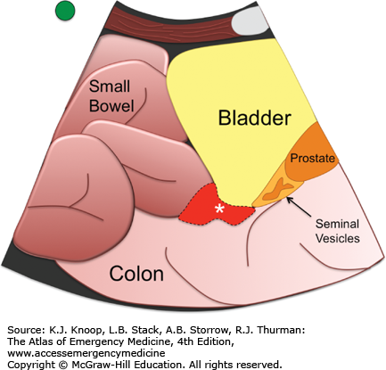
FIGURE 24.23
Hemoperitoneum, Sagittal Female. Hemoperitoneum is seen deep to the uterus, in the pouch of Douglas. Free fluid is seen as an anechoic (black) area in the rectouterine space as demarcated by the asterisk. (Illustration courtesy of Robinson M. Ferre, MD; ultrasound contributor: Jeremy S. Boyd, MD.)
It is important to remember that the bladder is within the pelvis; therefore, the transducer must be directed cephalad through the bladder into the peritoneum to evaluate for intraperitoneal fluid or hemorrhage in the rectovesicular or rectouterine space. If the prostate or vaginal stripe can be seen on a transverse suprapubic view, then the beam is directed caudal to the peritoneum and is missing from the peritoneal cavity entirely.
When in the sagittal plane, rotate the transducer 90 degrees counterclockwise directing the transducer indicator toward the patient’s right to obtain a transverse view.
An empty bladder will not be able to sufficiently displace the small bowel from the pelvis. This often prevents an adequate view of the dependent portions of the pelvis to assess for free peritoneal fluid. Filling the bladder through a Foley catheter or waiting for the bladder to distend will allow a better view for free intraperitoneal fluid that has collected in the pelvis.
THORAX (RIGHT AND LEFT)
Note that evaluation for thoracic fluid is best performed as an extension of the RUQ and LUQ views by sliding the transducer up into the chest in a coronal plane.
A linear or convex transducer is preferred for evaluation of pneumothorax.
A convex or phased array transducer is preferred for evaluation of hemothorax.
The transducer indicator is oriented toward the patient’s head.
With the indicator directed toward the patient’s head, the transducer is placed in the fifth or sixth intercostal space in the midaxillary line.
Identify the liver (on the right) or the spleen (on the left), the diaphragm, and the vertebral bodies that lie at the bottom of the screen.
In the fully inflated healthy lung, air prevents direct visualization of structures deep to the interface of the diaphragm and the visceral pleura of the lung. If fluid is present, it is identified as an anechoic (black) area that is caudal to the lung in the costophrenic recess. A hemothorax may have a simple anechoic appearance, but may also contain heterogeneous echoes from clotted blood or portion of lacerated lung tissue.
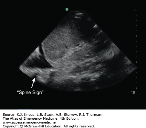
The presence of pleural fluid will allow direct visualization of the lung and posterior structures, including the vertebral bodies of the thoracic spine often referred to as the “spine sign” (Fig. 24.25).
FIGURE 24.25
Hemothorax. Fluid (in this case blood) is identified as an anechoic “wedge” above the diaphragm with loss of the normal mirroring artifact of the diaphragm allowing visualization of the spine extending beyond the costophrenic angle, also known as the “spine sign.” (Illustration courtesy of Robinson M. Ferre, MD; ultrasound contributor: Jeremy S. Boyd, MD.)
When using ultrasound to evaluate for a pneumothorax, the transducer is placed in the superior most portion of the chest wall in a supine patient to assess for normal apposition of the lung. Unlike chest radiography, ultrasound must look for normal apposition of the visceral and parietal portions of the lung in a stepwise fashion. Indeed, it is important to note that ultrasound can only assess for the presence or absence of a pneumothorax on the portion of the lung, where the transducer is currently imaging. Thus, when using ultrasound, we assume that there is no prior history of pleural scarring or pleural adhesions.
With the indicator directed toward the patient’s head, the transducer is placed just below the clavicle in the midclavicular line. To provide maximum sensitivity for the presence of a pneumothorax, the probe should be dragged caudal in the midclavicular line until the diaphragm is seen just below the costal margin (Fig. 24.26).
Once the probe is placed on the chest wall, identify the pectoralis and intercostal muscles and ribs with associated acoustic shadows that project to the bottom of the screen. The interface of the visceral and parietal pleura, known as the pleural line, will be seen immediately deep to the rib and intercostal muscle.
The depth should be adjusted so that the pleural line is positioned in the middle or upper half of the screen.
If there is normal apposition of the visceral and parietal pleura (no pneumothorax), sliding will be seen along the pleural line during normal respiration. If a pneumothorax is present, no sliding will be seen (Fig. 24.27).
B-lines, a type of comet tail artifact, are occasionally seen arising from the pleural line and will project to the bottom of the screen (see Lung Ultrasound). B-lines are only present if there is normal apposition of the visceral and parietal pleura. In essence, they “rule out” a pneumothorax at the portion of lung that is being imaged. If more than two B-lines are present in any one view, it indicates the presence of fluid within the extravascular lung tissue, which may indicate pulmonary contusion in the setting of trauma.
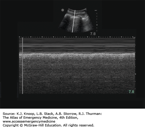
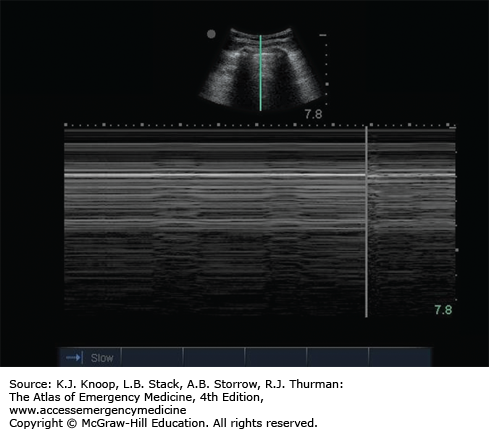
M-mode can assist with the detection and documentation of normal lung sliding. The “seashore sign,” described as “waves on the beach,” is noted with M-mode when no pneumothorax is present (Fig. 24.28). Conversely, a “stratosphere sign” is seen when a pneumothorax is present, the result of the M-mode tracing only a reverberation artifact (Fig. 24.29).
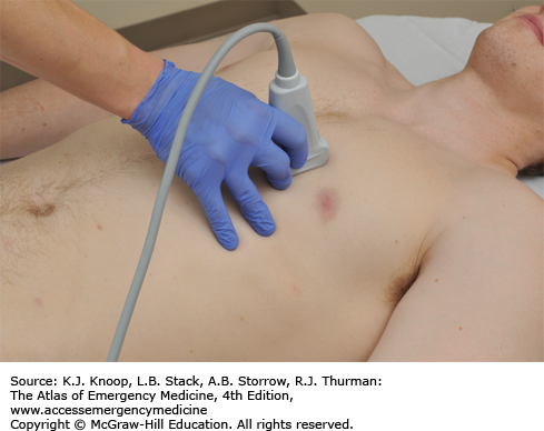
FIGURE 24.27
Pneumothorax. A still image of a pneumothorax as seen on ultrasound using a curvilinear or convex array transducer. The diagram illustrates the layer of air between the pleura causing the absence of “lung sliding” seen in real-time imaging. (Illustration courtesy of Robinson M. Ferre, MD; ultrasound contributor: Jeremy S. Boyd, MD.)
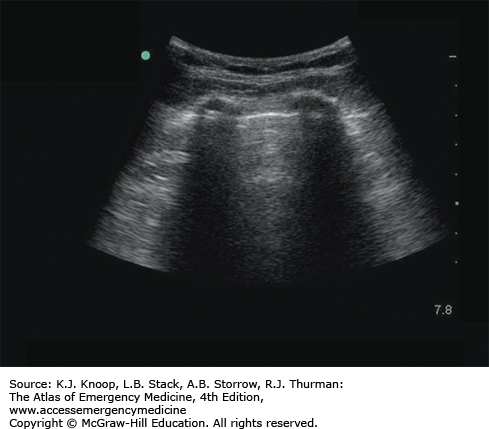
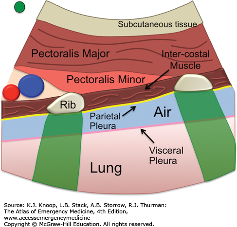
FIGURE 24.28
Seashore Sign. The “seashore sign” describes the M-mode appearance on thoracic ultrasound when there is no pneumothorax. The near-field image resembles waves on a beach, and the far-field image resembles a sandy beach, an artifact caused by lung sliding. (Ultrasound contributor: Jeremy S. Boyd, MD.)
Hemothorax: As visualized at the upper quadrants of the lateral chest, a hemothorax will appears as an anechoic (black) area between the diagphram and the lung within the costophrenic recess. Heterogeneous echoes may be present due to clotted blood, lacerated lung, or other material. The presence of pleural fluid will allow direct visualization of the lung and posterior structures, including the vertebral bodies of the thoracic spine often referred to as the “spine sign”(Fig. 24.25).
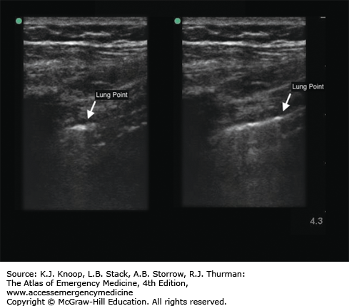
Pneumothorax: The absence of sliding along the pleural line is indicative of a pneumothorax. If lung sliding is absent, one should search for the leading edge of the pneumothorax, also known as lung point. Estimation of the pneumothorax size is possible by evaluating progressively more lateral views of the thorax in the supine patient.
Lung point is the point of transition from normal lung sliding to the absence of lung sliding that occurs at the leading edge of the pneumothorax. The finding of a “lung point” is 100% diagnostic of a pneumothorax (Fig. 24.30).
CARDIAC ULTRASOUND
Focused cardiac ultrasound can yield significant diagnostic information for the patient presenting with cardiac arrest, shock, shortness of breath, and a host of other complaints or physical findings. Although the intricacies of comprehensive echocardiography are beyond the scope of practice of most emergency medicine providers, with experience one can incorporate focused bedside cardiac ultrasound into the diagnostic armamentarium safely to answer specific diagnostic questions such as cardiac activity, volume status, gross cardiac function, right heart strain, and the presence of pericardial effusion.
It is important to note that by convention, unlike abdominal sonography, cardiac ultrasound is viewed with the transducer indicator displayed on the right of the screen. This will require the indicator on the transducer to be directed toward the patient’s left in an anatomically transverse view. This may be disorienting for many who have not performed cardiac ultrasound before. Most ultrasound systems include cardiac presets that automatically reverse the indicator orientation to the right of the display screen. The following section describes a sonographic approach for a conventionally oriented image using standard cardiac windows.
Cardiac arrest, pulseless electrical activity (PEA)
Penetrating thoracic/abdominal trauma
Unexplained hypotension or shock
Dyspnea
Chest pain
Acute myocardial infarction
Suspected aortic dissection
Specific pathologic states investigated with bedside cardiac ultrasound include asystole, cardiac activity, pericardial effusion, acute heart failure, aortic root dilatation/dissection, and right heart enlargement.
The sonographic windows for focused cardiac ultrasound include the subxiphoid view presented within the trauma/FAST examination as well as parasternal and apical views. Focused cardiac ultrasound utilizes standard views that are familiar to cardiologists and sonographers alike. These five windows allow the emergency physician to effectively and efficiently evaluate emergent cardiopulmonary pathology.
Subxiphoid/subcostal (SUBX; see E-FAST Examination, Subxiphoid View) (Fig. 24.31)
Parasternal long-axis view (PSLA)
Parasternal short-axis view (PSSA)
Apical four-chamber view (AP4)
Subxiphoid long-axis view (IVC)
The technique and common findings for each of these views are presented in the next five topics.
The patient should be optimally positioned in the left lateral decubitus position with the left arm above the head (allowing better access to the intercostal spaces) for all but the SUBX and IVC views, which should be performed with the patient supine. If this is not feasible, the patient may be supine for the entire study.
Phased array
SUBXIPHOID CARDIAC (SUBCOSTAL VIEW)
The transducer indicator should be directed toward the left in a cardiac preset.
With the transducer indicator pointing to the patient’s left, the transducer is placed inferior to the xiphoid process and directed cephalad toward the left shoulder in a horizontal plane (see Fig. 24.32).
Pivot, sweep, and tilt the transducer as needed to view all four cardiac chambers.
Identify the heart, four cardiac chambers, and surrounding pericardium (see Fig. 24.33).

Pericardial effusion: Pericardial fluid will appear as an anechoic (black) region noted between the pericardium and the right ventricle. As more fluid collects, the fluid will be seen completely surrounding all four chambers of the heart. Occasionally, internal echoes representing fibrin, clot, or cardiac tissue may be present within the pericardial space (Fig. 24.34).
Asystole: No cardiac activity present.
Hyperdynamic cardiac activity: Extensive cardiac contraction with near-total or complete collapse of the cardiac chambers, often associated with tachycardia and hypovolemia.
FIGURE 24.34
Pericardial Effusion. Pericardial fluid will appear as an anechoic (black) region noted between the pericardium and the right ventricle. Hypotensive patients with a pericardial effusion and findings such as right ventricular collapse (illustration) and/or a distended IVC warrant consideration of emergent pericardiocentesis. (Illustration courtesy of Robinson M. Ferre, MD; ultrasound contributor: Jeremy S. Boyd, MD.)
See “Pearls” for the “E-FAST Examination, Subxiphoid View.”
PARASTERNAL LONG-AXIS VIEW (PSLA)
The transducer indicator directed at the right clavicle or shoulder.
The transducer is placed in the fourth or fifth left parasternal intercostal space and the beam is directed posteriorly (Fig. 24.35).
Identify the right ventricle, left atrium, left ventricle, mitral valve, aortic valve, aortic root, aortic outflow tract, and surrounding pericardium (Fig. 24.36).

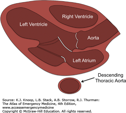
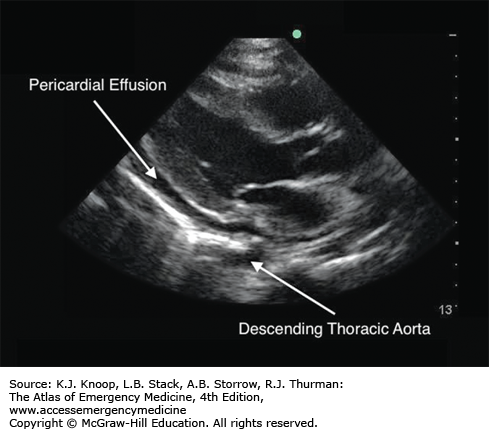
Pericardial effusion: Anechoic (black) region noted between the hyperechoic (bright) pericardium and the walls of the heart (see Fig. 24.37). In this view, pericardial effusion may be distinguished from a left-sided pleural effusion by its relationship to the descending thoracic aorta.
Aortic root dilatation: An aortic root measurement greater than 3.8 to 4.0 cm is abnormal and indicates aneurismal dilatation that may suggest aortic dissection in the appropriate clinical setting. Further evaluation is recommended.
Dilated descending aorta: The transverse descending thoracic aorta can be seen in the far field in this view posterior to the left atrium. A descending thoracic aorta greater than 4.0 cm is abnormal and indicates aneurismal dilatation that may suggest aortic dissection in the appropriate clinical setting. Further evaluation is recommended.
Poor left ventricular function: Gross estimates of left ventricular function may be made by observing the anteroposterior motion of the mitral valve, the increase in myocardial thickness with contraction, and the extent to which the anterior and posterior walls of the left ventricle approach each other in systole.
FIGURE 24.37
Parasternal Long-Axis View. A pericardial effusion is seen as an anechoic (black) region between the hyperechoic (bright) pericardium and the walls of the heart. The image demonstrates a small pericardial effusion, while the illustration demonstrates the location of a larger (circumferential) effusion. (Illustration courtesy of Robinson M. Ferre, MD; ultrasound contributor: Jeremy S. Boyd, MD.)
A true parasternal long-axis view (a sagittal image through the heart) will visualize the aortic root within the image. If the aortic root is not present, you are likely in an oblique plane and will need to angle the transducer to optimize the image.
It is critical to make deliberate, slow, small adjustments of the transducer in imaging the heart, since even small movements at the skin surface can translate into large changes in beam angle at just 5 to 10 cm deep from the surface.
Normal spontaneous respiration is usually fine for cardiac imaging. Patients who are tachypneic can be very challenging, and verbally coaching the patient’s breathing patterns is best. If you note a great deal of artifact due to lung interposition, place the patient in the left lateral decubitus position; have him or her inhale and slowly exhale while you scan. When you have an acceptable window, ask the patient to stop exhaling and hold his or her breath while you capture your images.
Remember that the parasternal long axis is approximated by a line running from the right acromioclavicular joint and the left antecubital fossa (when the arm is lying by the patient’s side).
PARASTERNAL SHORT-AXIS VIEW (PSSA)
From the parasternal long-axis position, rotate the transducer 90 degrees clockwise (to the patient’s left) or place the transducer in the fourth or fifth left parasternal intercostal space in a line connecting the left clavicle/shoulder and the right hip (Fig. 24.38).
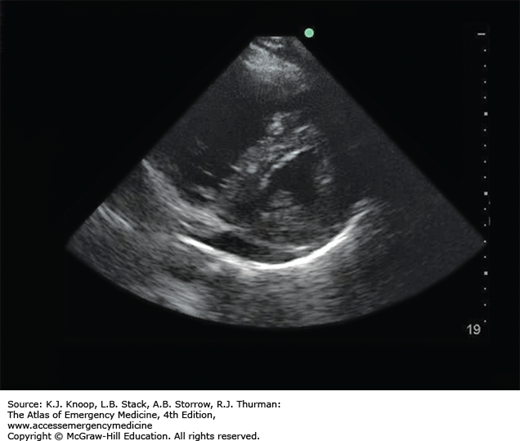
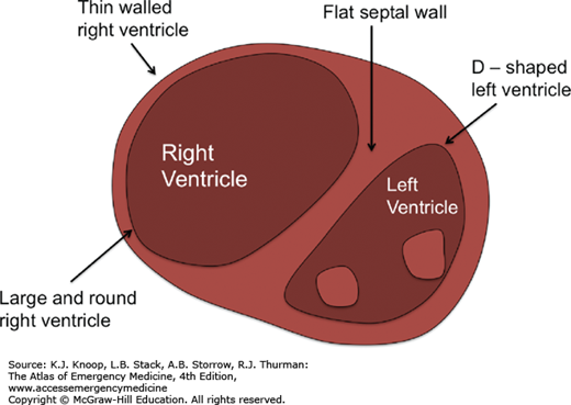
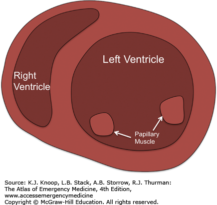
Identify the left ventricle (circular), right ventricle (crescent-shaped), and surrounding pericardium (Fig. 24.39).
FIGURE 24.38
Parasternal Short-Axis View. Place the transducer in the fourth or fifth left parasternal intercostal space in a line connecting the left clavicle/shoulder and the right hip, with the transducer rotated 90 degrees clockwise from the parasternal long-axis view. (Photo contributor: Lawrence B. Stack, MD.)
Pericardial effusion: Anechoic (black) region noted between the bright pericardium and the walls of the heart (Fig. 24.37).
Dilated right ventricle: The right ventricle is normally a crescent-shaped structure. A rounded, dilated right ventricle that deforms the rounded left ventricle (creating an “OD” sign) suggests elevated right-sided pressures, as seen with pulmonary emboli and severe pulmonary hypertension (Fig. 24.40).