Electrical and Fire Safety
The myriad electronic devices in the modern operating room (OR) greatly improve patient care and safety but also subject patients and OR personnel to increased risks (Ehrenwerth J, Seifert HA. Electrical and fire safety. In: Barash PG, Cullen BF, Stoelting RK, Cahalan MK, Ortega R, Stock MC, eds. Clinical Anesthesia. Philadelphia: Lippincott Williams & Wilkins; 2013: 189–218).
I. Principles of Electricity
A basic principle of electricity is known as Ohm’s law and is represented by the equation E = I × R (electromotive force in volts = current in amperes times resistance in ohms). Ohm’s law forms the basis for the physiologic equation in which the blood pressure is equal to the cardiac output times the systemic vascular resistance (BP = CO × SVR). Electrical power is measured as watts (voltage × amperage). The amount of electrical work done (watt-second or joule) is a common designation for electrical energy expended. (Energy produced by a defibrillator is measured in joules.)
Direct and Alternating Currents. The flow of electrons (current) through a conductor is characterized as direct current (electron flow is always in the same direction) or alternating current (electron flow reverses direction at a regular interval).
Impedance is the sum of forces that oppose electron movement in an alternating current circuit.
Capacitance is the ability of a capacitor (two parallel conductors separated by an insulator) to store charge.
In a direct current circuit, the charged capacitor plates (battery) do not result in current flow unless a resistance is connected between the two plates and the capacitor is discharged.
Stray capacitance is capacitance that is not designed into the system but is incidental to the construction of the equipment. All alternating current operating equipment produces stray capacitance even while turned off.
II. Electrical Shock Hazards
Alternating and Direct Currents
Whenever an individual contacts an external source of electricity, an electrical shock is possible. (It requires
approximately three times as much direct current as alternating current to cause ventricular fibrillation [VF].)
A short circuit occurs when there is zero impedance with a high current flow.
Source of Shocks
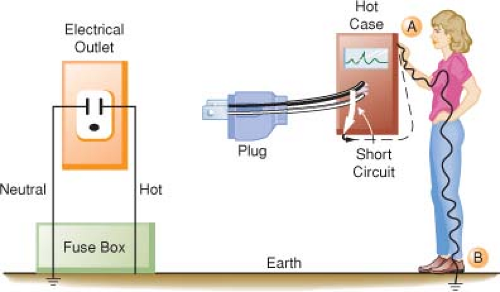
Electrical accidents or shocks occur when a person becomes part of or completes an electrical circuit (Fig. 8-1).
Damage from electrical current is caused by disruption of normal electrical function of cells (skeletal muscle contracture, VF) or dissipation of electrical energy (burn).
The severity of an electrical shock is determined by the amount of current and the duration of current flow.
Macroshock describes large amounts of current flow that can cause harm or death.
Microshock describes small amounts of current flow and applies only to electrically susceptible patients (those with an external conduit that is in direct contact with the heart, such as a pacing wire or saline-filled central venous pressure [CVP] catheter) in whom even minute amounts of current (1 mA, which is the threshold of perception) may cause VF.
Very high-frequency current does not excite contractile tissue and does not cause cardiac dysrhythmias.
Grounding. To fully understand electrical shock hazards and their prevention, one must have a thorough knowledge of the concepts of grounding. In electrical terminology, grounding is applied to electrical power and equipment.
III. Electrical Power: Grounded
Electrical utilities universally provide power to homes that are grounded. (By convention, the earth ground potential is zero.)
Electrical shock is an inherent danger of grounded power systems. An individual standing on ground or in contact with an object that is referenced to the ground needs only one additional contact point to complete the circuit.
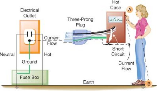
Modern wiring systems have added a third wire (a low-resistance pathway through which the current can flow to ground) to decrease the severity of potential electrical shocks (Fig. 8-2).
IV. Electrical Power: Ungrounded
The numerous electronic devices, along with power cords and puddles of saline-filled solutions on the floor, tend to make
the OR an electrically hazardous environment for both patients and personnel.
In an attempt to decrease the risk of electrical shock, the power supplied to most ORs is ungrounded (current is isolated from the ground).
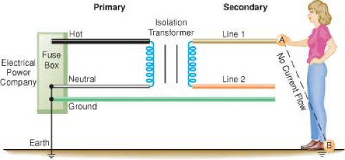
Supplying ungrounded power to an OR requires the use of an isolation transformer (Fig. 8-3).
The isolated power system provides protection from macroshock (Fig. 8-4).
A faulty piece of equipment plugged into an isolated power system does not present a shock hazard.
V. The Line Isolation Monitor
The line isolation monitor is a device that continuously monitors the integrity of an isolated power system (i.e., it measures the impedance to ground on each side of the isolated power system).
If a faulty piece of equipment is connected to the isolated power system, it will, in effect, change the system to a conventional grounded system, yet the faulty piece of equipment will continue to function normally.
The meter of the line isolation monitor indicates the amount of leakage in the system resulting from any device plugged into the isolated power system.
Visual and audible alarms are triggered if the isolation from the ground has been degraded beyond a predetermined limit (Fig. 8-5).
If the line isolation monitor alarm is triggered, the first step is to determine if it is a true fault.
Stay updated, free articles. Join our Telegram channel

Full access? Get Clinical Tree


