ECG basics
One of the most valuable diagnostic tools available, an electrocardiogram (ECG) records the heart’s electrical activity as waveforms. By interpreting these waveforms accurately, you can identify rhythm disturbances, conduction abnormalities, and electrolyte imbalances. An ECG aids in diagnosing and monitoring such conditions as myocardial infarction (MI) and pericarditis.
To interpret an ECG correctly, you must first recognize its key components. Next, you need to analyze the key components separately. Then you can put your findings together to reach a conclusion about the heart’s electrical activity. This chapter explains that analytic process, beginning with some fundamental information about electrocardiography.
The heart’s electrical activity produces currents that radiate through the surrounding tissue to the skin. When electrodes are attached to the skin, they sense the electrical currents and transmit them to the electrocardiograph. This electrical activity is transformed into waveforms that represent the heart’s depolarization-repolarization cycle.
Myocardial depolarization occurs when a wave of stimulation passes through the heart and causes the heart muscle to contract. Repolarization is the relaxation phase. An ECG shows the precise sequence of electrical events occurring in the cardiac cells throughout that process and identifies rhythm disturbances and conduction abnormalities.
Leads and planes
Because the electrical currents from the heart radiate to the skin in many directions, electrodes are placed at different locations to get a total picture of the heart’s electrical activity. The ECG can
then record information from different perspectives, which are called leads and planes.
then record information from different perspectives, which are called leads and planes.
Leads
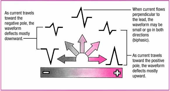
A lead provides a view of the heart’s electrical activity between two points, or poles. Each lead consists of one positive and one negative pole. Between the two poles lies an imaginary line representing the lead’s axis, a term that refers to the direction of the current moving through the heart. Because each lead measures the heart’s electrical potential from different directions, each lead generates its own characteristic tracing. (See Current direction and waveform deflection.)
The direction in which the electric current flows determines how the waveforms appear on the ECG tracing. When the current flows along the axis toward the positive pole of the electrode, the waveform deflects upward and is called a positive deflection. When the current flows away from the positive pole, the waveform deflects downward, below the baseline, and is called a negative deflection. When the current flows perpendicular to the axis, the wave may go in both directions or be unusually small. When electrical activity is absent
or too small to measure, the waveform is a straight line, also called an isoelectric deflection.
or too small to measure, the waveform is a straight line, also called an isoelectric deflection.
Planes
A plane is a cross section of the heart that provides a different view of the heart’s electrical activity. In the frontal plane—a vertical cut through the middle of the heart from top to bottom—electrical activity is viewed from an anterior to posterior approach. The six limb leads are viewed from the frontal plane.
In the horizontal plane—a transverse cut through the middle of the heart dividing it into upper and lower portions—electrical activity can be viewed from a superior or an inferior approach. The six precordial leads are viewed from the horizontal plane.
Types of ECG recordings
The two main types of ECG recordings are the 12-lead ECG and the rhythm strip. Both types give valuable information about the heart’s electrical activity.
12-lead ECG
A 12-lead ECG records information from 12 different views of the heart and provides a complete picture of electrical activity. These 12 views are obtained by placing electrodes on the patient’s limbs and chest. The limb leads and the chest, or precordial, leads reflect information from the different planes of the heart.
Different leads provide different information. The six limb leads—I, II, III, augmented vector right (aVR), augmented vector left (aVL), and augmented vector foot (aVF)—provide information about the heart’s frontal plane. Leads I, II, and III require a negative and positive electrode for monitoring, which makes these leads bipolar. The augmented leads—aVR, aVL, and aVF— are unipolar, meaning they need only a positive electrode.
The six precordial, or V, leads—V1, V2, V3, V4, V5, and V6—provide information about the heart’s horizontal plane. Like the augmented leads, the precordial leads are unipolar, requiring only a positive electrode. The negative pole of these leads, which is in the center of the heart, is calculated by the ECG.
Rhythm strip
A rhythm strip provides continuous information about the heart’s electrical activity from one or more leads simultaneously.
Commonly monitored leads include lead II, V1, and V6. A rhythm strip is used to monitor cardiac status. Chest electrodes pick up the heart’s electrical activity for display on the monitor. The monitor also displays heart rate and other measurements and can print out strips of cardiac rhythms.
Commonly monitored leads include lead II, V1, and V6. A rhythm strip is used to monitor cardiac status. Chest electrodes pick up the heart’s electrical activity for display on the monitor. The monitor also displays heart rate and other measurements and can print out strips of cardiac rhythms.
ECG monitoring systems
The type of ECG monitoring system used—hardwire monitoring or telemetry—depends on the patient’s clinical status. With hardwire monitoring, the electrodes are connected directly to the cardiac monitor. Most hardwire monitors are mounted permanently on a shelf or wall near the patient’s bed. Some monitors are mounted on an I.V. pole for portability, and some may include a defibrillator.
The monitor provides a continuous cardiac rhythm display and transmits the ECG tracing to a console at the nurses’ station. Both the monitor and the console have alarms and can print rhythm strips to show ectopic beats, for example, or other arrhythmias. Hardwire monitors also have the ability to track pulse oximetry, blood pressure, hemodynamic measurements, and other parameters through various attachments to the patient.
Hardwire monitoring is generally used in critical care units and emergency departments because it permits continuous observation of one or more patients from more than one area in the unit. However, this type of monitoring has disadvantages, including limited mobility because the patient is tethered to a monitor.
With telemetry monitoring, the patient carries a small, battery-powered transmitter that sends electrical signals to another location, where the signals are displayed on a monitor screen. This type of ECG monitoring frees the patient from cumbersome wires and cables and protects him from the electrical leakage and accidental shock occasionally associated with hardwire monitoring.
Telemetry monitoring still requires skin electrodes to be placed on the patient’s chest. Each electrode is connected by a thin wire to a small transmitter box that’s carried in a pocket or pouch. Telemetry monitoring is especially useful for detecting arrhythmias that occur at rest or during sleep, exercise, or stressful situations. Most systems, however, can monitor only heart rate and rhythm.
Electrode placement
Electrode placement is different for each lead, and different leads provide different views of the heart. A lead may be chosen to highlight a particular part of the ECG complex or the electrical events of a specific area of the heart.
Dual lead monitoring
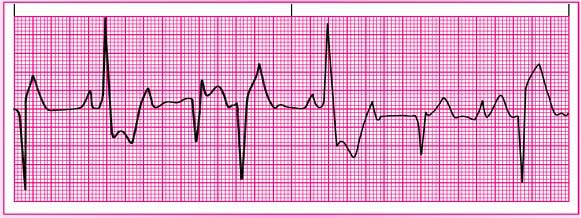
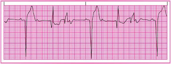
Monitoring in two leads provides a more complete picture than monitoring in only one lead. With simultaneous dual monitoring, you’ll generally review the first lead—usually designated as the primary lead—for arrhythmias.
A two-lead view helps detect ectopic beats or aberrant rhythms. Leads II and V1 are the leads most commonly monitored simultaneously.
Lead II
 |
Lead V1
 |
Although leads II, V1, and V6 are among the most commonly used leads for continuous monitoring, lead placement is varied according to the patient’s clinical status. If your monitoring system has the capability, you may also monitor the patient in more than one lead. (See Dual lead monitoring.)
Standard limb leads
All standard limb leads or bipolar limb leads have a third electrode, known as the ground, which is placed on the chest to prevent electrical interference from appearing on the ECG recording.
Lead I provides a view of the heart that shows current moving from right to left. Because current flows from negative to positive, the positive electrode for this lead is placed on the left arm or on the left side of the chest; the negative electrode is placed on the right arm. Lead I produces a positive deflection on ECG tracings and is helpful in monitoring atrial rhythms.
Lead II produces a positive deflection. The positive electrode is placed on the patient’s left leg and the negative electrode on the right arm. For continuous monitoring, place the electrodes on the torso for convenience, with the positive electrode below the lowest palpable rib at the left midclavicular line and the negative electrode below the right clavicle. The current travels down and to the left in this lead. Lead II tends to produce a positive, high-voltage deflection, resulting in tall P, R, and T waves. This lead is commonly used for routine monitoring and is useful for detecting sinus node and atrial arrhythmias and monitoring the inferior wall of the left ventricle.
Lead III usually produces a positive deflection. The positive electrode is placed on the left leg and the negative electrode on the left arm. Along with lead II, this lead is useful for detecting changes associated with an inferior wall of the left ventricle.
The axes of the three bipolar limb leads—I, II, and III—form a triangle around the heart and provide a frontal plane view of the heart. (See Einthoven’s triangle.)
Related posts:


Stay updated, free articles. Join our Telegram channel

Full access? Get Clinical Tree


