Classification of Mechanical Ventilators and Modes of Ventilation: Introduction
A good ventilator classification scheme describes how ventilators work in general terms, but with enough detail so that one particular model can be distinguished from others. It facilitates description by focusing on key attributes in a logical and consistent manner. A clear description allows us to quickly assess new facts in relation to our previous knowledge. Learning the operation of a new ventilator or describing it to others then becomes much easier. Understanding how the ventilator operates, we can then anticipate appropriate ventilator management strategies for particular clinical situations. The classification system described in this chapter is based on previously published work.1–7
A ventilator is simply a machine, a system of related elements designed to alter, transmit, and direct energy in a predetermined manner to perform useful work. We put energy into the ventilator in the form of electricity (energy = volts × amps × time) or compressed gas (energy = pressure × volume). That energy is transmitted or transformed (by the ventilator’s drive mechanism) in a predetermined manner (by the control circuit) to augment or replace the patient’s muscles in performing the work of breathing. Thus to understand mechanical ventilators in general, we must first understand their basic functions: (a) power input, (b) power transmission or conversion, (c) control scheme, and (d) output. This simple format can be expanded to add as much detail as desired (Table 2-1).
|
|
Control System
To understand how a machine can be controlled to replace or supplement the natural function of breathing, we need to first understand something about the mechanics of breathing itself. The study of mechanics deals with forces, displacements, and the rate of change of displacement. In physiology, force is measured as pressure (pressure = force/area), displacement as volume (volume = area × displacement), and the relevant rate of change as flow [average flow = Δvolume/Δtime; instantaneous flow ( ) = dv/dt, the derivative of volume with respect to time]. Specifically, we are interested in the pressure necessary to cause a flow of gas to enter the airway and increase the volume of the lungs.
The study of respiratory mechanics is essentially the search for simple but useful models of respiratory system mechanical behavior. Figure 2-1 illustrates the process by which the respiratory system is represented first by a graphical model, and then by a mathematical model based on the graphical model. Pressure, volume, and flow are measurable variables in the mathematical model that change with time over the course of one inspiration and expiration. The relation among them is described by the equation of motion for the respiratory system.9 The derivation of this equation stems from a force-balance equation that is an expression of Newton’s third law of motion (for every action, there is an equal and opposite reaction):
Figure 2-1
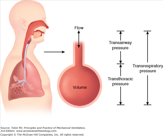
The respiratory system is often modeled as a single flow resistance (representing the endotracheal tube and the airways) connected to an elastic chamber (representing the lungs and chest wall). Flow through the airways is generated by transairway pressure (pressure at the airway opening minus pressure in the lungs). Expansion of the elastic chamber is generated by transthoracic pressure (pressure in the lungs minus pressure on the body surface). Transrespiratory pressure (pressure at the airway opening minus pressure on the body surface) is the sum of these two pressures and is the total pressure required to generate inspiration. The “airway-pressure” gauge on a positive-pressure ventilator displays transrespiratory pressure.
where PTR is the transrespiratory pressure (i.e., pressure at the airway opening minus pressure at the body surface), PE is the pressure caused by elastic recoil (elastic load), and PR is the pressure caused by flow resistance (resistive load).
Transrespiratory pressure can have two components, one generated by the ventilator (Pvent) and one generated by the respiratory muscles (Pmus). Elastic recoil pressure is the product of elastance (E = Δpressure/Δvolume) and volume. Resistive pressure is the product of resistance (R = Δpressure/Δflow) and flow. Thus, Eq. (1) can be expanded to yield the following equation for inspiration:
The combined ventilator and muscle pressure causes volume and flow to be delivered to the patient. (Of course, muscle pressure may subtract rather than add to ventilator pressure in the case of patient–ventilator dyssynchrony, in which case both volume and flow delivery are reduced.) Pressure, volume, and flow are functions of time and are called variables. They are all measured relative to their values at end-expiration. Elastance and resistance are assumed to remain constant and are called parameters.
For passive expiration, both ventilator and muscle pressure are absent, so Eq. (2) becomes
The negative sign on the left side of the equation indicates flow in the expiratory direction. This equation also shows that passive expiratory flow is generated by the energy stored in the elastic compartment (i.e., lungs and chest wall) during inspiration.
Equation (2) shows that if the patient’s respiratory muscles are not functioning, muscle pressure is zero, and the ventilator must generate all the pressure for inspiration. On the other hand, a ventilator is not needed for normal spontaneous breathing (i.e., vent pressure = 0). Between those two extremes, an infinite number of combinations of muscle pressure (i.e., patient effort) and ventilator pressure are possible under the general heading of “partial ventilator support.” The equation of motion also gives the basis for defining an assisted breath as one for which ventilator pressure rises above baseline during inspiration or falls below baseline during expiration.
In the equation of motion, the mathematical form of any of the three variables (i.e., pressure, volume, or flow as functions of time) can be predetermined, making it the independent variable and making the other two the dependent variables. We now have a theoretical basis for classifying ventilators as pressure, volume, or flow controllers. Thus, during pressure-controlled ventilation, pressure is the independent variable and may take the form of, say, a step function (i.e., a rectangular pressure waveform). The shapes of the volume and flow waveforms for a passive respiratory system (Pmus = 0) then depends on the shape of the pressure waveform as well as the parameters of resistance and compliance. On the other hand, during volume-controlled ventilation, we can specify the shape of the volume waveform making flow-dependent and pressure-dependent variables. The same reasoning applies to a flow controller. Notable exceptions are interpulmonary percussive ventilation, and high-frequency oscillatory ventilation, both of which control only the duration of flow pulses; the resulting airway pressure pulses along with actual inspiratory flows and volumes depend on the instantaneous values of respiratory system impedance. Because neither pressure, volume, nor flow in the equation of motion are predetermined, we would classify this type of device as a “time controller.”
It follows from the preceding discussion that any conceivable ventilator can control only one variable at a time: pressure, volume, or flow. Because volume and flow are inverse functions of one another, we can simplify our discussion and consider only pressure and volume as control variables. I discuss later in “Modes of Ventilation” exactly how ventilator control systems work. We will see that it is possible for a ventilator to switch quickly from one control variable to another, not only from breath to breath, but even during a single inspiration.
Because breathing is a periodic event, the ventilator must be able to control a number of variables during the respiratory cycle (i.e., the time from the beginning of one breath to the beginning of the next). Mushin et al10 proposed that this time span be divided into four phases: the change from expiration to inspiration, inspiration, the change from inspiration to expiration, and expiration. This convention is useful for examining how a ventilator starts, sustains, and stops an inspiration and what it does between inspirations. A particular variable is measured and used to start, sustain, and end each phase. In this context, pressure, volume, flow, and time are referred to as phase variables.11 Figure 2-2 shows the criteria for determining phase variables.

All ventilators measure one or more variables associated with the equation of motion (i.e., pressure, volume, flow, or time). Inspiration is started when one of these variables reaches a preset value. Thus, the variable of interest is considered an initiating, or trigger, variable. Time is a trigger variable when the ventilator starts a breath according to a set frequency independent of the patient’s spontaneous efforts. Pressure is the trigger variable when the ventilator senses a drop in baseline pressure caused by the patient’s inspiratory effort and begins a breath independent of the set frequency. Flow or volume are the trigger variables when the ventilator senses the patient’s inspiratory effort in the form of either flow of volume into the lungs.
Flow triggering reduces the work the patient must perform to start inspiration.12 This is so because work is proportional to the volume the patient inspires times the change in baseline pressure necessary to trigger. Pressure triggering requires some pressure change and hence an irreducible amount of work to trigger. With flow or volume triggering, however, baseline pressure need not change, and theoretically, the patient need do no work on the ventilator to trigger.
The patient effort required to trigger inspiration is determined by the ventilator’s sensitivity setting. Some ventilators indicate sensitivity qualitatively (“min” or “max”). Alternatively, a ventilator may specify a trigger threshold quantitatively (e.g., 5 cm H2O below baseline). Once the trigger variable signals the start of inspiration, there is always a short delay before flow to the patient starts. This delay is called the response time and is secondary to the signal-processing time and the mechanical inertia of the drive mechanisms. It is important for the ventilator to have a short response time to maintain optimal synchrony with patient inspiratory effort.
Here target means restricting the magnitude of a variable during inspiration. A target variable is one that can reach and maintain a preset level before inspiration ends (i.e., it does not end inspiration). Pressure, flow, or volume can be target variables and actually all can be active for a single breath (e.g., using the Pmax feature on a Dräger ventilator). Note that time cannot be a target variable because specifying an inspiratory time would cause inspiration to end, violating the preceding definition. Astute readers may notice that in the past I have used the term limit where here I have used target. This was done to be consistent with the International Standards Organization’s use of the term limit as applying to alarm situations only.
Clinicians often confuse target variables with cycle variables. To cycle means “to end inspiration.” A cycle variable always ends inspiration. A target variable does not terminate inspiration; it only sets an upper bound for pressure, volume, or flow (Fig. 2-3).
Figure 2-3
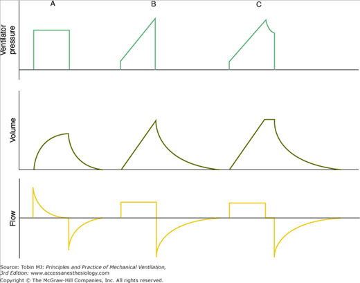
This figure illustrates the distinction between the terms target and cycle. A. Inspiration is pressure-targeted and time-cycled. B. Flow is targeted, but volume is not, and inspiration is volume-cycled. C. Both volume and flow are targeted, and inspiration is time-cycled. (Reproduced, with permission, from Chatburn.6)
The inspiratory phase always ends when some variable reaches a preset value. The variable that is measured and used to end inspiration is called the cycle variable. The cycle variable can be pressure, volume, flow, or time. Manual cycling is also available on some ventilators.
When a ventilator is set to pressure cycle, it delivers flow until a preset pressure is reached, at which time inspiratory flow stops and expiratory flow begins. The most common application of pressure cycling on mechanical ventilators is for alarm settings.
When a ventilator is set to volume cycle, it delivers flow until a preset volume has passed through the control valve. By definition, as soon as the set volume is met, inspiratory flow stops and expiratory flow begins. If expiration does not begin immediately after inspiratory flow stops, then an inspiratory hold has been set, and the ventilator is, by definition, time cycled (see Fig. 2-3). Note that the volume that passes through the ventilator’s output control valve is never exactly equal to the volume delivered to the patient because of the volume compressed in the patient circuit. Some ventilators use a sensor at the Y-connector (such as the Dräger Evita 4 with the neonatal circuit) for more accurate tidal volume measurement. Others measure volume at some point inside the ventilator, and the operator must know whether the ventilator compensates for compressed gas in its tidal volume readout.
When a ventilator is set to flow cycle, it delivers flow until a preset level is met. Flow then stops, and expiration begins. The most frequent application of flow cycling is in the pressure-support mode. In this mode, the control variable is pressure, and the ventilator provides the flow necessary to meet the inspiratory pressure target. In doing so, flow starts out at a relatively high value and decays exponentially (assuming that the patient’s respiratory muscles are inactive after triggering). Once flow has decreased to a relatively low value (such as 25% of peak flow, typically preset by the manufacturer), inspiration is cycled off. Manufacturers often set the cycle threshold slightly above zero flow to prevent inspiratory times from getting so long that patient synchrony is degraded. On some ventilators, the flow-cycle threshold may be adjusted by the operator to improve patient synchrony. Increasing the flow-cycle threshold decreases inspiratory time and vice versa.
Time cycling means that expiratory flow starts because a preset inspiratory time interval has elapsed.
The baseline variable is the parameter controlled during expiration. Although pressure, volume, or flow could serve as the baseline variable, pressure control is the most practical and is implemented by all modern ventilators. Baseline or expiratory pressure is always measured and set relative to atmospheric pressure. Thus, when we want baseline pressure to equal atmospheric pressure, we set it to zero. When we want baseline pressure to exceed atmospheric pressure, we set a positive value, called positive end-expiratory pressure (PEEP).
Modes of Ventilation
The general goals of mechanical ventilation are to promote safety, comfort, and liberation (Table 2-2).1 Specific objectives under these goals include ensuring adequate gas exchange, avoiding ventilator induced lung injury, optimizing patient-ventilator synchrony, and minimizing the duration of ventilation. The preset pattern of patient-ventilator interaction designed to achieve these objectives is referred to as a mode of ventilation. Specifically, a mode can be classified according to the outline in Table 2-3.2
|
|
I have already mentioned that pressure, volume, or flow can be controlled during inspiration. When discussing modes I will refer to inspiration as being pressure-controlled or volume-controlled. Ignoring flow control is justified because when the ventilator controls volume directly (i.e., using a volume-feedback signal), flow is controlled indirectly, and vice versa (i.e., mathematically, volume is the integral of flow, and flow is the derivative of volume).
There are clinical advantages and disadvantages to volume and pressure control. To keep within the scope of this chapter, we can just say that volume control results in a more stable minute ventilation (and hence more stable blood gases) than pressure control if lung mechanics are unstable. On the other hand, pressure control allows better synchronization with the patient because inspiratory flow is not constrained to a preset value. Although the ventilator must control only one variable at a time during inspiration, it is possible to begin a breath-in pressure control and (if certain criteria are met) switch to volume control or vice versa (referred to as dual targeting, described in “Targeting Schemes” below).
The breath sequence is the pattern of mandatory or spontaneous breaths that the mode delivers. A breath is a positive airway flow (inspiration) relative to baseline, and it is paired (by size) with a negative airway flow (expiration), both associated with ventilation of the lungs. This definition excludes flow changes caused by hiccups or cardiogenic oscillations. It allows, however, the superimposition of, for example, a spontaneous breath on a mandatory breath or vice versa. The flows are paired by size, not necessarily by timing. In airway pressure-release ventilation, for example, there is a large inspiration (transition from low pressure to high pressure) possibly followed by a few small inspirations and expirations, followed finally by a large expiration (transition from high pressure to low pressure). These comprise several small spontaneous breaths superimposed on one large mandatory breath. During high-frequency oscillatory ventilation, in contrast, small mandatory breaths are superimposed on larger spontaneous breaths.
A spontaneous breath, in the context of mechanical ventilation, is a breath for which the patient determines both the timing and the size. The start and end of inspiration may be determined by the patient, independent of any machine settings for inspiratory time and expiratory time. That is, the patient both triggers and cycles the breath. On some ventilators, the patient may make short, small spontaneous efforts during a longer, larger mandatory breath, as in the case of airway pressure-release ventilation. It is important to make a distinction between spontaneous breaths and assisted breaths. An assisted breath is one for which the ventilator does some work for the patient, as indicated by an increase in airway pressure (i.e., Pvent) above baseline during inspiration or below baseline during expiration. For example, in the pressure-support mode, each breath is assisted because airway pressures rise to the pressure-support setting above PEEP (i.e., Pvent > 0). Each breath is also spontaneous because the patient both triggers and cycles the breath. The patient may cycle the breath in the pressure-support mode by actively exhaling, but even if the patient is passive at end-inspiration, the patient’s resistance and compliance determine the cycle point and thus the size of the breath for a given pressure-support
Related posts:


Stay updated, free articles. Join our Telegram channel

Full access? Get Clinical Tree


