The Ventilator as a “Black Box”
A mechanical ventilator is an automatic machine designed to provide all or part of the work the body must do to move gas into and out of the lungs. The act of moving air into and out of the lungs is called breathing, or, more formally, ventilation.
The simplest mechanical device we could devise to assist a person’s breathing would be a hand-driven, syringe-type pump that is fitted to the person’s mouth and nose using a mask. A variation of this is the self-inflating, elastic resuscitation bag. Both of these require one-way valve arrangements to cause air to flow from the device into the lungs when the device is compressed, and out from the lungs to the atmosphere as the device is expanded. These arrangements are not automatic, requiring an operator to supply the energy to push the gas into the lungs through the mouth and nose. Thus, such devices are not considered mechanical ventilators.
Automating the ventilator so that continual operator intervention is not needed for safe, desired operation requires three basic components:
A source of input energy to drive the device;
A means of converting input energy into output energy in the form of pressure and flow to regulate the timing and size of breaths; and
A means of monitoring the output performance of the device and the condition of the patient.
There was a time when you could take a handful of simple tools and do routine maintenance on your car engine. About that time the average clinician could also completely disassemble and reassemble a mechanical ventilator as a training exercise or to perform repairs. In those days (the late 1970s), textbooks1 describing ventilators understandably paid much attention to the individual mechanical components and pneumatic schematics. In fact, this philosophy was reflected to some extent in previous editions of this book. Today, both cars and ventilators are incredibly complex mechanical devices controlled by multiple microprocessors running sophisticated software (Fig. 3-1). Figure 3-2 shows the pneumatic schematic of a current intensive care ventilator. All but the most rudimentary maintenance of ventilators is now the responsibility of specially trained biomedical engineers. Our approach to describing ventilator design has thus changed from a focus on individual components to a more generalized model of a ventilator as a “black box,” that is, a device for which we supply an input and expect a certain output and whose internal operations are largely unknowable, indeed, irrelevant, to most clinical operators. What follows, then, is only a brief overview of the key design features of mechanical ventilators with an emphasis on input power requirements, transfer functions (pneumatic and electronic control systems), and outputs (pressure, volume, and flow waveforms). The rest of the chapter focuses on the interactions between the operator and the ventilator (the operator interface), and between the ventilator and the patient (the patient interface).
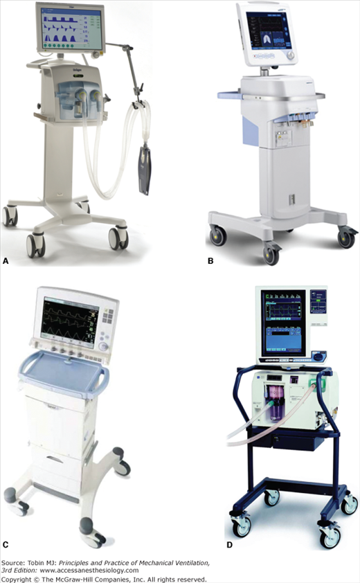
Figure 3-2
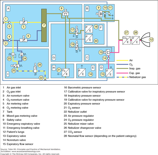
Pneumatic schematic of the Dräger Infinity V500 intensive care ventilator. A. Gas-mixture and gas-metering assembly. Gas from the supply lines enters the ventilator via the gas-inlet connections for oxygen and air (1,2). Two nonreturn valves (3,4) prevent one gas from returning to the supply line of the other gas. Mixing takes place in the tank (7) and is controlled by two valves (5,6). Inspiratory flow is controlled by a third valve (8). B. Inspiratory unit consists of safety valve (9) and two nonreturn valves (10,11). In normal operation, the safety valve is closed so that inspiratory flow is supplied to the patient’s lungs (12). During standby, the safety valve is open and enables spontaneous inspiration by the emergency breathing valve (11). The emergency expiratory valve (10) provides a second channel for expiration when the expiratory valve (13) is blocked. C. Expiratory unit consists of the expiratory valve (13) and a nonreturn valve (14). The expiratory valve is a proportional valve and is used to adjust the pressure in the patient circuit. In conjunction with the spring-loaded valve of the emergency air outlet (10), the nonreturn valve (14) prevents pendulum breathing during spontaneous breathing. D. Expiratory flow sensor. E. Barometric pressure sensor. Conversion of mass flow to volume, body temperature and pressure saturated (BTPS) requires knowledge of ambient pressure. F. Pressure measurement assembly. Pressure in the patient circuit is measured with two independent pressure sensors (18,20). G. Calibration assembly. The pressure sensors are regularly zero calibrated by connection to ambient pressure via the two calibration valves (17,19). H. Oxygen sensor. I. Medication nebulizer assembly. (Reproduced, with permission, from Dräger Medical AG & Co. KG. V500 Operator’s Manual. Luebeck, Germany.)
Mechanical ventilators are typically powered by electricity or compressed gas. Electricity, either from wall outlets (e.g., 100 to 240 volts AC, at 50/60 Hz) or from batteries (e.g., 10 to 30 volts DC), is used to run compressors of various types. Batteries are commonly used as the primary power source in the home-care environment but are usually reserved for patient transport or emergency use in hospitals. These sources provide compressed air for motive power as well as air for breathing. Alternatively, the power to expand the lungs is supplied by compressed gas from tanks, or from wall outlets in the hospital (e.g., 30 to 80 pounds per square inch [psi]). Some transport and emergency ventilators use compressed gas to power both lung inflation and the control circuitry. For these ventilators, knowledge of gas consumption is critical when using cylinders of compressed gas.
The ventilator is generally connected to separate sources of compressed air and compressed oxygen. In the United States, hospital wall outlets supply air and oxygen at 50 psi, although most ventilators have internal regulators to reduce this pressure to a lower level (e.g., 20 psi). This permits the delivery of a range of oxygen concentrations to support the needs of sick patients. Because compressed gas has all moisture removed, the gas delivered to the patient must be warmed and humidified so as to avoid drying out the lung tissue.
The input power of a ventilator must be converted to a predefined output of pressure and flow. There are several key systems required for this process. If the only power input is electrical, the ventilator must use a compressor or blower to generate the required pressure and flow. A compressor is a machine for moving a relatively low flow of gas to a storage container at a higher level of pressure (e.g., 20 psi). A blower is a machine for generating relatively larger flows of gas as the direct ventilator output with a relatively moderate increase of pressure (e.g., 2 psi). Compressors are generally found on intensive care ventilators whereas blowers are used on home-care and transport ventilators. Compressors are typically larger and consume more electrical power than blowers, hence the use of the latter on small, portable devices.
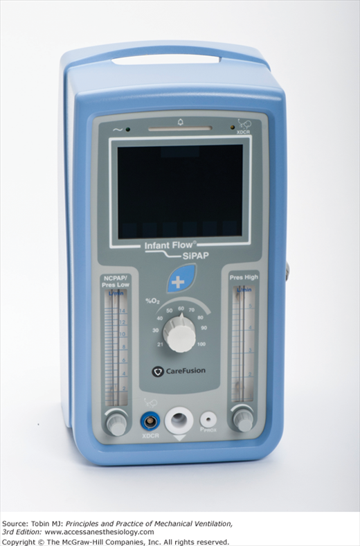
To control the flow of gas from a compressor, ventilator engineers use a variety of flow-control valves, from very simple to very complex. The simplest valve is just a fixed orifice flow resistor that permits setting a constant flow to the external tubing that conducts the gas to the patient, called the patient circuit. Such devices are used in small transport ventilators and automatic resuscitators. Manually adjusted variable-orifice flow meters have been used in simple infant ventilators in the past (e.g., Bourns BP-200) and are currently used in the Infant Flow SiPAP device (CareFusion, Minneapolis, MN), as shown in Figure 3-3. The advent of inexpensive microprocessors in the 1980s led to development of digital control of flow valves that allow a great deal of flexibility in shaping the ventilator’s output pressure, volume, and flow waveforms (Fig 3-4).2 Such valves are used in most of the current generation of intensive care ventilators.
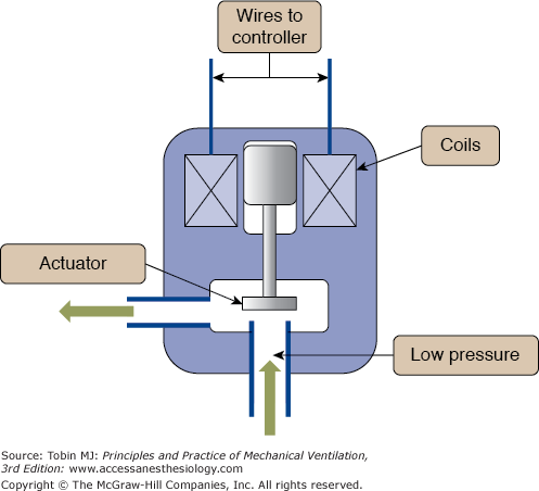
Directing flow from the source gas into the patient requires the coordination of the output flow-control valve and an expiratory valve or “exhalation manifold” (Fig. 3-5). In the simplest case, when inspiration is triggered on, the output control valve opens, the expiratory valve closes, and the only path left for gas is into the patient. When inspiration is cycled off, the output valve closes and the exhalation valve opens, flow from the ventilator ceases and the patient exhales out through the expiratory valve (see Fig. 3-2). The most sophisticated ventilators employ a complex interaction between the output flow-control valve and the exhalation valve, such that a wide variety of pressure, volume, and flow waveforms may be generated to synchronize the ventilator output with patient effort as much as possible.
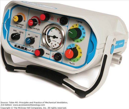
In the simplest terms, the control system of a ventilator is comprised of components that generate the signals that operate the output valve and the exhalation manifold to obtain the desired output waveforms and modes of ventilation. Control systems may be based on mechanical, pneumatic, fluidic, or electronic components. Mechanical components include levers, pulleys, cams, and so on.3 Pneumatic control circuits use gas pressure to operate diaphragms, jet entrainment devices, pistons, and other items. Use of lasers to create micro channels for gas flow has enabled miniaturization of ventilator control circuits that are powered entirely by gas pressure to create small, but sophisticated, ventilators for transport, such as the CAREvent (O-Two Medical Technologies) shown in Figure 3-6. Fluidic circuits are analogs of electronic logic circuits.4 Just as an electronic logic circuit uses electricity, the fluidic circuit uses a very small gas flows to generate signals that operate switches and timing components. Both pneumatic and fluidic control systems are immune to failure from electromagnetic interference, such as around magnetic resonance imaging equipment. Examples of simple pneumatic and fluidic ventilator control circuits have been illustrated elsewhere.5 By far, the majority of ventilators use electronic control circuits with microprocessors to manage the complex monitoring (e.g., from pressure and flow sensors) and control (valves) functions of modern ventilators used in almost every health care environment.
What makes one ventilator so different from another has as much to do with the control system software as it does with the hardware. The control software determines how the ventilator interacts with the patient; that is, the modes available. Thus, a discussion about control systems is essentially a discussion about mode capabilities and classifications. Chapter 2 describes the specific design principles of ventilator control systems in detail.
Just as the study of cardiology involves the use of electrocardiograms and blood pressure waveforms, the study of mechanical ventilation requires an understanding of output waveforms. The waveforms of interest are the pressure, volume, and flow.
Output waveforms are conveniently graphed in groups of three. The horizontal axis of all three graphs is the same and has the units of time. The vertical axes are in units of pressure, volume, and flow. For the purpose of identifying characteristic waveform shapes, the specific baseline values are irrelevant. What is important is the relative magnitudes of each of the variables and how the value of one affects or is affected by the value of the others.
Figure 3-7 illustrates the typical waveforms available on modern ventilators. These waveforms are idealized; that is, they are precisely defined by mathematical equations and are meant to characterize the operation of the ventilator’s control system. As such, they do not show the minor deviations, or “noise,” often seen in waveforms recorded during actual ventilator use. This noise can be caused by a variety of extraneous factors such as vibration and flow turbulence. Of course, scaling of the horizontal and vertical axes can affect the appearance of actual waveforms considerably. Finally, the waveforms in Figure 3-7 do not show the effects of the resistance and compliance of the patient circuit.
Figure 3-7
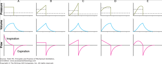
Idealized ventilator output waveforms. A. Pressure-controlled inspiration with a rectangular pressure waveform. B. Volume-controlled inspiration with a rectangular flow waveform. C. Volume-controlled inspiration with an ascending-ramp flow waveform. D. Volume-controlled inspiration with a descending-ramp flow waveform. E. Volume-controlled inspiration with a sinusoidal flow waveform. The short dashed lines represent mean inspiratory pressure, and the long dashed lines represent mean pressure for the complete respiratory cycle (i.e., mean airway pressure). Note that mean inspiratory pressure is the same as the pressure target in A. These waveforms were created as follows: (a) defining the control waveform using a mathematical equation (e.g., an ascending-ramp flow waveform is specified as flow = constant × time), (b) specifying the tidal volume for flow-control and volume-control waveforms, (c) specifying the resistance and compliance, (d) substituting the preceding information into the equation of motion for the respiratory system, and (e) using a computer to solve the equation for the unknown variables and plotting the results against time. (Reproduced, with permission, from Chatburn RL. Fundamentals of Mechanical Ventilation. Cleveland Heights, OH: Mandu Press; 2003:143.)
No ventilator is an ideal pressure, volume, or flow controller, and ventilators are designed to only approximate a particular waveform. Idealized waveforms as shown in Figure 3-7 are, nevertheless, helpful because they are used commonly in other fields (e.g., electrical engineering), which makes it possible to use mathematical procedures and terminology that already have been established. For example, a standard mathematical equation is used to describe the most common ventilator waveforms for each control variable. This known equation may be substituted into the equation of motion, which is then solved to get the equations for the other two variables. Once the equations for pressure, volume, and flow are known, they are easily graphed. This is the procedure that was used to generate the graphs in Figure 3-7.
The pressure, volume, and flow the patient actually receives are never precisely the same as what the clinician sets on the ventilator. Sometimes these differences are caused by instrument inaccuracies or calibration error. More commonly, the patient delivery circuit contributes to discrepancies between the desired and actual patient values. This is so because the patient circuit has its own compliance and resistance. Thus, the pressure measured inside a ventilator upstream of the patient always will be higher than the pressure at the airway opening because of patient circuit resistance. In addition, the volume and flow coming out of the ventilator’s exhalation manifold will exceed those delivered to the patient because of the compliance of the patient circuit.
Exactly how the mechanical properties of the patient circuit affect ventilator performance depends on whether they are connected in series or in parallel with the patient. It turns out that the resistance of the patient circuit is connected in series whereas the compliance is modeled as a parallel connection. To understand this, we first make the simplifying assumption that we can examine the patient circuit’s resistance separate from its compliance. It is intuitively obvious that the same flow of gas that comes from the ventilator travels through the circuit tubing as through the patient’s airway opening. We also can see that the pressure drop across the patient circuit will be different from that across the respiratory system because they have different resistances. By a definition we borrow from electronics, when two circuit components share the same flow but have different pressure drops, they are connected in series. This means that the patient circuit resistance, however small, adds to the total resistive load seen by the ventilator. Thus, in a volume-controlled breath, the peak inspiratory pressure is higher, and in a pressure-controlled breath, the tidal volume and peak flow are lower. In practice, the effect of patient circuit resistance is usually ignored because it is so much lower than the resistance of the respiratory system.
Now consider the patient circuit compliance. The effective compliance of the patient circuit is a combination of the tubing compliance and the compressibility of the gas inside it. As the ventilator delivers the breath to the patient, pressure at the airway opening rises relative to atmospheric pressure, which is the driving force for flow into the lungs. The patient circuit is connected between the ventilator and the airway, so the pressure it experiences across its walls is the same as that experienced by the respiratory system (remember that we are ignoring its resistance now, so we can ignore any pressure drop between the ventilator outlet and the airway opening). The volume change of the patient circuit tubing is different from that of the respiratory system because the compliance of the circuit is different. Because the patient circuit and the respiratory system fill with different volumes during the same inspiratory time, the flows they experience are different (remember that flow = volume ÷ time). Again borrowing a definition from electronics, if two circuit components share the same pressure drop but different flows, they are connected in parallel. Because they are in parallel, the two compliances are additive, so the total compliance is greater than either component.
Patient circuit compliance sometimes can be greater than respiratory system compliance and thus can have a large effect on ventilation. It must be accounted for either automatically by the ventilator or manually by increasing the tidal volume. For example, when ventilating neonates, patient circuit compliance can be as much as three times that of the respiratory system, even with small-bore tubing and a small-volume humidifier. Thus, when trying to deliver a preset tidal volume during volume-controlled ventilation, as little as 25% of the set volume will be delivered to the patient, with 75% compressed in the patient circuit. The compliance of the patient circuit can be determined by occluding the tubing at the patient Y, delivering a small volume under flow control (using zero positive end-expiratory pressure [PEEP]), and noting the resulting pressure. Using a short inspiratory hold will make it easier to read the pressure. Then compliance is calculated as before, by dividing the volume by the pressure. Once the patient circuit compliance is known, the set tidal volume can be corrected using the following equation:
where Vdelivered is the tidal volume delivered to the patient, Vset is the tidal volume setting on the ventilator, CPC is the patient circuit compliance, and CRS is the respiratory system compliance.
We can get a more intuitive understanding of this equation if we put in some values. Suppose, for example, that we use the perfect patient circuit that has zero compliance. Substituting zero for CPC, we get
which shows that there is no effect on the delivered tidal volume. Suppose now that CPC is as large as CRS (i.e., CPC = CRS). Now we have
in which case, half the volume from the ventilator goes to the patient, and the other half is compressed in the patient circuit. Some ventilators automatically compensate for gas lost to the patient circuit.2
The effect of the patient circuit is more troublesome during volume-controlled modes than during pressure-controlled modes. This is so because during volume control, the ventilator meters out a specific volume of gas, and unless it measures flow at the airway opening, it has no way of knowing how much goes to the patient and how much goes to the patient circuit. In contrast, during pressure-controlled modes, the ventilator simply meters out a set pressure change no matter where the gas goes. Because the respiratory system and the patient circuit compliance are in parallel, they both experience the same driving pressure (peak inspiratory pressure minus end-expiratory pressure), so tidal volume delivery is affected very little. The only effect might be that the patient circuit compliance may tend to increase the pressure rise time, which would tend to decrease peak flow and tidal volume slightly.
Another area where patient circuit compliance causes trouble is in the determination of auto-PEEP. There are several methods for determining auto-PEEP. One method to determine auto-PEEP during mechanical ventilation is to create an expiratory hold manually (i.e., delay the next inspiration) until static conditions prevail throughout the lungs (i.e., no flow anywhere in the lungs). The pressure at this time (total PEEP) minus the applied PEEP is an estimation of global auto-PEEP. Note that auto-PEEP may vary throughout the lungs depending on the distribution of lung disease and may not reflect pressure behind collapsed areas in patients with severe flow limitation. Auto-PEEP is an index of the gas trapped in the system at end expiration secondary to an insufficient expiratory time:
where Vtrapped is the volume of gas trapped in the patient and the patient circuit at end-expiration (above that associated with applied PEEP), and Ctotal is the total compliance of the respiratory system and the patient circuit. The problem is that we want auto-PEEP to reflect the gas trapped in the patient, not in the circuit. If we know the compliances of the patient circuit and the respiratory system, we can correct the measured auto-PEEP as follows:
where true auto-PEEP is that which exists in the lungs, measured auto-PEEP is the amount of end-expiratory pressure in equilibration with the lungs and the patient circuit, CRS is the respiratory system compliance, and CPC is the patient circuit compliance. If the ventilator displays auto-PEEP on its monitor, check the ventilator’s operating manual to see whether or not the auto-PEEP calculation is corrected for patient circuit compliance. The larger CPC is relative to CRS, the larger will be the error. Again, the error will be most noticeable in pediatric and neonatal patients.
The Operator Interface
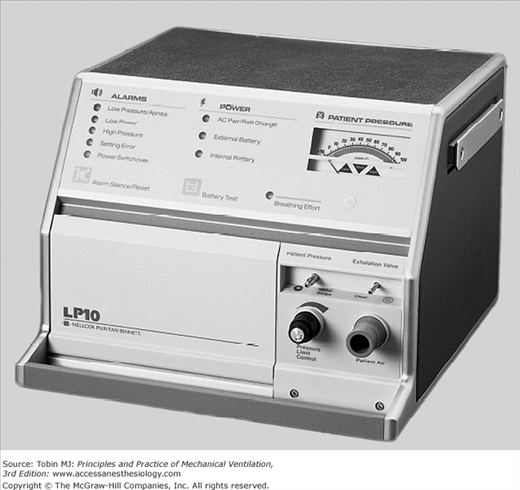
The operator interaction with the ventilator mainly happens through the ventilator display. The display or interface has evolved in parallel with the ventilators. The key to this evolution are the technological advances in the last three decades.2 The microprocessors, the digital displays, and the interactive screens have all permeated from other technological advances into the ventilator world. There are still remnants of the evolutionary process. In their initial ventilator generations, the interface had no or minimal manifestation of the interaction with the patient. The operator would enter the ventilator settings by using knobs or buttons that regulated simple functions (pressure, flow, or time). The results of these changes were evaluated in the patient clinical response, and occasionally through simple pressure analog displays. Some ventilators still use these type of displays (e.g., CareFusion 3100A high-frequency oscillator and Puritan Bennett LP-10, Fig. 3-8).
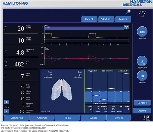
Most of the ventilators produced in the last decade have advanced displays, including liquid crystal displays and color touch screens with one or more multipurpose knobs or buttons. This allows the user to scroll through different menus and to select and activate the selections (e.g., Hamilton G5 ventilator, Fig. 3-9). The operator can customize the screen to the operator’s needs. Current ventilators allow graphical displays of alarms, settings, respiratory system calculations, and measurements. The ventilator display evolution has not necessarily resulted in easier management of the ventilator. These advances brought issues with the amount of information displayed, the actions taken with that information, and the ease of use of certain interfaces.6 As the level of sophistication has increased, we have been able to increase the number of ventilation parameters monitored. This requires a new level of training and understanding of human behavior. For example, a mode of ventilation may be preferentially chosen based on the amount of alarms it triggers,7 or its ease of use.6,8
The operator input refers to parameters or settings entered by the operator of the ventilator. Each mode of ventilation has particular features, some of which can be adjusted by the operator. We describe here the most common adjustable parameters. The effect of each parameter on the lung is better understood under the light of the equation of motion (see Chapter 2).9,10 A change of one parameter will lead to changes in others (i.e., in volume control, for the same respiratory characteristics changing the tidal volume will cause a change in peak airway pressure). Furthermore, knowing the basic construction and characteristics of a mode of ventilation (volume vs. pressure control breaths) or the breath sequence (mandatory vs. spontaneous) will help understand how the setting will affect the ventilator output (see Chapter 2).
The operator input is presented below in the order that follows the progression of a breath; starting with the gas inhaled, to triggering, targeting, cycling, and baseline variables.
A mechanical ventilator has the capacity of delivering different mixtures of gas. Most ventilators allow the administration of specific concentrations of oxygen. A few allow the administration of helium, nitric oxide, or anesthesia gases.
Oxygen is the most common gas administered to patients undergoing mechanical ventilation. The oxygen percentage in the inspired gas (FIO2) can be regulated in most ventilators by means of a direct adjustment of a specific control (21% to 100%). However, this is not true for all ventilators. For example, some home ventilators (e.g., LP-10 or the LTV 1150, Pulmonetic, CareFusion) use a connection to a low-pressure oxygen source to the ventilator or the patient circuit. The following formula can calculate the flow of oxygen to achieve a desired oxygen concentration:
where O2 required is 100% oxygen flow in L/min, f is the breathing frequency in breaths/min, VT is the tidal volume in liters and the FIO2 is the patient O2 concentration desired in decimal format (i.e., 30% = 0.3). An oxygen analyzer should be used to confirm the measurements. It must be recognized that changes in oxygen flow, breathing rate, or tidal volume will change the FIO2.
When transporting the critically ill patient, availability of oxygen supplies for the mechanically ventilated patient is crucial. Size and weight of cylinders makes transport difficult and presents an increased risk of fire. Branson et al. have described a solution using a portable oxygen concentrator (SeQual Eclipse II) paired with the Impact 754 and Pulmonetics LTV-1200 ventilators.11
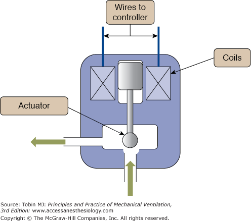
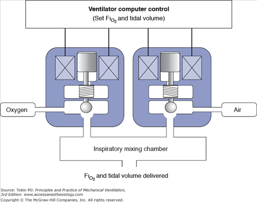
For the rest of the current mechanical ventilators, the ventilator adjusts the mixture of air and oxygen to achieve the desired FIO2. The mixing of air is achieved by an internal or external blender. A blender may use proportioning valves that regulate the flow of air and oxygen to a mixing changer (Fig. 3-10). It is similar to the mechanism used to mix hot and cold water in a shower—the more oxygen needed, the larger the opening for oxygen and the smaller it is for air. To work properly, the blender requires a constant pressure within the working ranges of the device.
Most current ventilators have oxygen sensors to monitor the FIO2. The oxygen sensor gives feedback to the operator to adjust the mixture, or alarms if there is a discrepancy between the set and delivered FIO2. The oxygen sensors detect changes in electrical current, which is proportional to the oxygen concentration. The most common techniques are: (a) paramagnetic, (b) polarographic, and (c) galvanic.12
Mixtures of helium and oxygen (heliox, HeO2) instead of air and oxygen are occasionally used to help patients on mechanical ventilation with obstructive airway diseases. Helium is less dense than air (Table 3-1).13 The decrease in density interferes with flow measurements, inspiratory and expiratory valve accuracy, and gas mixing.14 Several studies have evaluated the performance of mechanical ventilators delivering heliox14–16 and have shown that heliox does affect the performance of the ventilator. The interference of heliox is more evident in volume-control modes than in pressure-control modes.14,17 In pressure-control mode, the ventilator targets a set inspiratory pressure and the delivered tidal volume is dependent only on the mechanical properties of the respiratory system. The time constant may decrease but the delivered volume should be the same as for nonheliox gas delivery. In volume-control mode, delivered volume may be larger than, smaller than, or the same as expected depending on the design of the ventilator.14 Only a few ventilators (Maquet Servo i with heliox option, Hamilton G5 with heliox option, and the Viasys Avea with comprehensive model) are designed and calibrated for heliox delivery. Otherwise, the operator needs to be aware of the specific ventilator performance and correction formulas and factors14 such that potentially hazardous conditions do not develop.
Inhaled nitric oxide (NO) is used as selective pulmonary vasodilator for patients with pulmonary hypertension, life-threatening hypoxia, or right-heart failure. Different devices to deliver NO have been described in the literature. Most of them were custom made and required the use of mixing chambers, stand-alone NO/nitric dioxide monitors, and manual titration of the gas flow. The large amount of custom-made devices led to inconsistent administration of NO.18 In 1998, the American Society for Testing Materials (ASTM) committee on anesthetic and respiratory equipment developed a standard to provide a minimum degree of safety of the devices used to deliver NO. The recommendation was to use a NO administration apparatus, and a NO/nitrogen dioxide analyzer. The Food and Drug Administration (FDA) enforces this recommendation, and so far, only one device is approved in the United States. The INOvent (Ikaria Inc, Clinton, NJ) delivery system uses a closed-loop scheme to measure and deliver NO in proportion to the inspiratory flow from the ventilator. NO is injected in the proximal limb of the inspiratory circuit, and measured close to the connection between the patient circuit and the endotracheal tube. Two portable systems are available—INO Max DS (Ikaria) and AeroNOx (PulmoNOx, Alberta, CA). As these devices are not universally available, the following formula19 can be used to calculate the NO flow rate required to achieve a desired concentration of NO when injected in the inspiratory limb at a constant gas flow,
where QNO is the flow rate of nitric oxide in L/min, CNOset is the desired NO concentration in parts per million (ppm), CNOcyl is the NO concentration in the cylinder in ppm (usually 800 ppm) and the QV is the ventilator gas flow.
The formula is accurate for constant flow systems. This presents a major problem when used with intermittent breaths (as most modes of ventilation) the patient will receive variable amounts of NO (a “bolus” with each mechanical breath).20 Furthermore, whenever the ventilator settings or the patient breathing pattern changes, the NO delivery will change. Finally, the use of NO will alter the gas delivery of the ventilator. For example, the INOvent system will add gas to and extract gas from the delivered breath. At 80 ppm it adds 10% more gas, although it also withdraws 230 mL/min through the gas-sampling port. Thus, the oxygen delivered will decrease, and the tidal volume may increase. The changes seem to be small (unless you see it in pediatric proportions), but it may affect the ventilator’s performance. Furthermore, as a flow of gas is introduced, the flow-triggering performance may be affected.
A ventilator-assisted breath can be started (triggered) by the machine or the patient. A machine-triggered breath is defined by the start of the inspiratory phase independent of any signal from the patient. The operator typically sets a breath frequency for machine-triggered breaths. A patient-triggered breath is one for which inspiration is started solely by a signal from the patient. The key operator set variable for patient triggering is sensitivity, or the magnitude of the patient signal required to initiate inspiratory flow. The patient signal can be obtained from measuring the airway pressure, flow, volume, electromyogram (EMG),21 abdominal motion (Graseby capsule22), thoracic impedance,23 or any other measurable signal of respiratory activity.24 Most intensive care ventilators measure pressure and flow (volume is integrated from flow) at the circuit. There are only a few ventilators that use other sources of signaling, diaphragmatic EMG (Servo i NAVA), thoracic impedance (Sechrist SAVI), and abdominal motion (Infant Star STAR SYNC, which is no longer commercially available).24,25
Ventilator triggering characteristics can be evaluated using different metrics.23,26–28 The most sophisticated device for evaluating ventilator performance is the ASL lung simulator (IngMar Medical Ltd., Pittsburgh, PA). This device can simulate both passive lung mechanics (e.g., resistance and compliance) as well as patient inspiratory and expiratory effort. It can display and record pressure, volume, and flow signals, and calculate a wide variety of performance metrics. Figure 3-11 shows an example of these waveforms with specific reference points for calculating performance metrics (from operator’s manual for software version 3.2). Using these reference points we can define the following key trigger metrics: Pmin (maximum pressure drop relative to PEEP during the trigger phase), pressure-time product (∫ Paw-PEEP dt from start of effort to return of airway pressure [Paw] to PEEP), patient trigger work (∫ Paw-PEEP dv from start of effort to return of Paw, to PEEP), and time to trigger (period from the start of effort to the return of Paw to PEEP).
Figure 3-11
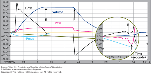
Reference points on pressure, volume, and flow waveforms recorded by the ASL 5000 (IngMar Medical Ltd, Pittsburgh, PA). A. Start of inspiratory effort, B. beginning of inhalation as determined by the “breath start volume threshold,” C. lowest pressure during the trigger phase, Pmin, D. return of airway pressure to baseline during the trigger phase, E. end of inspiratory time, i.e., negative-going zero flow crossing, F. beginning of exhalation as determined by the “expiratory start volume threshold,” and G. end of expiratory time, i.e., positive-going zero flow crossing. (Reproduced, with permission, from Ingmar Medical. ASL 5000 v3.2 Operator’s Manual. Pittsburgh, PA: Author.)
Time is measured by the internal ventilator processor. The next breath is time triggered (in the absence of a patient trigger event) when the expiratory time has reached the threshold to maintain a set respiratory rate (e.g., if the set rate is 10 breaths per minute and the inspiratory time is set at 1 second, then the expiratory time is 5 seconds). Some modes allow the user to set the inspiratory and expiratory time [e.g., airway pressure release ventilation (APRV) and biphasic], thus fixing the inspiratory-to-expiratory timing (I:E) ratio and respiratory rate. In an effort to improve patient–ventilator interactions, the ventilator may synchronize the mandatory breath with the patient’s triggering signal if it falls within a threshold. The classic example is synchronized intermittent mandatory ventilation (SIMV). More recently APRV, as programmed in the Evita XL, delivers a machine breath if the patient trigger signal falls within 25% of the triggering time.29 Time triggering is also found as a safety mechanism. The operator or manufacturer enters a time after which the apnea alarm will trigger the delivery of a preset breath after a preset time is reached.
The patient inspiratory effort causes a drop in pressure in the airway and the circuit. Inspiration starts when pressure falls below the preset “sensitivity” threshold. The site of measurement will have an impact on the performance of the device. Pressure signals travel at the speed of sound, approximately 1 ft/ms.30 The farther the sensor is from the signal source, the longer the potential time delay. The closest measurements can be done in the trachea. Tracheal pressure measurements reflect actual airway pressure as the endotracheal tube resistance is bypassed. When used for ventilator triggering, tracheal pressure sensing results in decreased work of breathing.31–33 However, tracheal pressure measurements are not routinely done and require special equipment (endotracheal tube with monitoring port) and no current ventilator uses it to routinely trigger the ventilator.
The other sites of pressure measurement are the patient circuit Y or at the inspiratory or expiratory ports, each with its advantages and disadvantages (Table 3-2). Trigger performance will also be affected by the presence of humidifiers, filters, water condensation, patient circuit and exhalation valves. These will most often dampen, or rarely amplify, the pressure signal. Clinically, the presence of a dampened signal will require a larger pressure change (higher work of breathing) to reach the trigger threshold. On the contrary, presence of water in the pressure tubing may cause oscillation, which can falsely trigger mechanical breaths.
| Advantages | Disadvantages |
|---|---|
| A. Exhalation port: Well protected from mechanical abuse. During mechanical inhalation, accurately reads pressure at the Y. During inhalation, increases in inspiratory or expiratory circuit resistance do not compromise inspiratory flow output, except for manyfold increases. | Requires protection from moisture of exhaled gas. During spontaneous inspiration, underestimates pressure generated at the Y to trigger the ventilator. During exhalation, underestimates pressure at the Y. During exhalation, increases in expiratory circuit resistance compromise expiratory flow. Hence, system requires well-maintained expiratory filter to ensure that expiratory circuit resistance remains low. |
| B. Inhalation port: Well protected from mechanical abuse. Does not require protection from moisture or additional filters. During exhalation, accurately reads pressure at the Y as long as the inspiratory circuit remains patient. During inhalation, increases in expiratory circuit resistance do not compromise inspiratory-flow output. | During mechanical inhalation, overestimates pressure at the Y. During spontaneous inspiration, underestimates pressure generated at the Y to trigger the ventilator. During inhalation, increases in inspiratory circuit resistance compromise inspiratory flow output. For example, factors such as selection of humidifier and type of patient circuit yield varying patient inspiratory efforts for fixed ventilator settings. |
| C. Patient Y: During inhalation and exhalation, accurately reads both inspiratory and expiratory pressures. Pressure readings reflect relative condition of inspiratory and expiratory circuits. | Susceptible to mechanical abuse. Requires a separate pressure-sensing tube, which is prone to occlusion, blockage, and disconnection, all of which prevent sensing of patient effort. |
The trigger pressure sensitivity is usually set at 0.5 to 1.5 cm H2O below the baseline pressure. Common practice is to increase the sensitivity (i.e., decrease the pressure drop) until autotriggering occurs and then reduce sensitivity until the autotriggering just stops.30 Note that each ventilator comes with predetermined manufacturer set values and can be adjusted.
Related posts:


Stay updated, free articles. Join our Telegram channel

Full access? Get Clinical Tree


