Chapter 3 Vaporizers
Laws of vaporization
Factors affecting vaporization of a liquid
Temperature
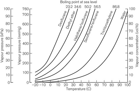
Vaporization is increased if the temperature of the liquid is raised, since more molecules will have been given sufficient kinetic energy to escape. Fig. 3.1 shows the vapour pressure curves of volatile anaesthetic agents (as well as water) and shows how they vary with temperature. If the liquid is heated, a point is reached at which vaporization now occurs not only at the surface of the liquid, but also in vapour bubbles that develop within its substance. The liquid is now boiling and this temperature is its boiling point. At this temperature, the SVP of the liquid is equal to the ambient atmospheric pressure.
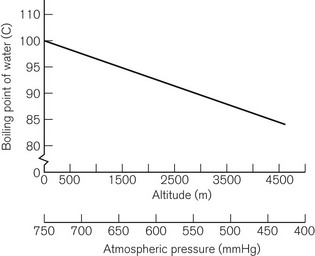
The boiling point of a liquid may therefore vary with atmospheric pressure. At high altitudes (where the air is thinner, has a lower ambient pressure and therefore exerts less pressure on the surface of a liquid) there is a significant depression of the boiling point. This may render the administration of agents with low boiling points, such as ether, difficult. Fig. 3.2 shows the depression of the boiling point for water with change in atmospheric pressure.
Volatility
The speed at which a liquid vaporizes depends not only on its ambient temperature and pressure, but also on its volatility. A more volatile liquid has weaker cohesive forces between its molecules, such that they require less energy (i.e. a lower temperature) to vaporize (Fig. 3.1). This is reflected in a higher SVP at any temperature and a lower boiling point.
Vaporizing systems
A modern vaporizer needs to be constructed so that it provides a suitable, stable and predictable concentration of anaesthetic vapour for admixture with other patient gasses. The delivered amount of vapour must not be affected by changes in temperature, and flow rates of other gasses.
Types of vaporizer
Appropriate vaporization may be achieved by either:
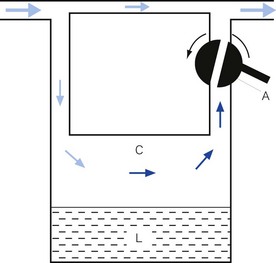
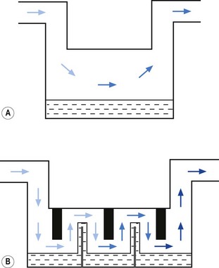
• splitting the patient gas flow so that only a portion passes through the vaporizer. This picks up saturated vapour and then leaves to mix with the remainder of the gas that has gone through a bypass. The final concentration may be altered by varying the splitting ratio between bypass gas flow and vaporizer gas flow, using an adjustable valve. This type is often referred to as a variable bypass vaporizer (Fig. 3.3); or
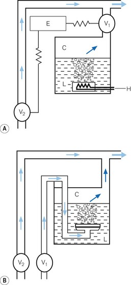
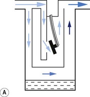
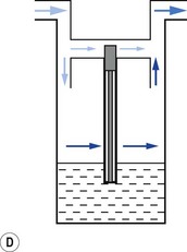
• alternatively, the vaporizer can be constructed so that it heats the anaesthetic agent to a temperature above its boiling point (in order that it may behave as a gas) and which can then be metered into the fresh gas flow (Fig. 3.4A). Similarly, a vaporizer may contain a fine metal sieve that is submerged in the anaesthetic agent and through which a small independent and metered gas supply (normally oxygen) can be made to pass. The minute bubbles produced have a very large surface area and produce a saturated vapour at ambient pressure, which can then be passed into the fresh gas flow (Fig. 3.4B). These types of vaporizer are often referred to as measured flow vaporizers.
It should also be noted that the various anaesthetic inhalational agents currently available have widely differing potencies and physical properties and hence require devices constructed specifically for each agent. Very potent agents (halothane, enflurane, sevoflurane, isoflurane and desflurane) require vaporizers that can accurately control the concentration of vapour leaving the vaporizer. However, agents such as diethyl ether, with a lower potency, may be used safely with simpler apparatus (if necessary), in which the vapour concentration is not accurately known, since there is less risk of over-dosage (see Chapter 27).
Variable bypass vaporizers
Design features
Surface area of contact between carrier gas and the liquid
Vaporizers, which are required to be very accurate, should always present a saturated vapour to the bypass gas across a wide range of flows. To ensure sufficient vaporization at the highest planned flow, a sufficiently large surface area of liquid should be present. This size is also governed by the volatility of the agent used. A highly volatile liquid will require a smaller surface area. The surface area for vaporization of a liquid can be increased by causing it to spread (by capillarity) over a large sheet of porous material which may be folded in such a way that the carrier gas passes across its entire surface (Fig. 3.5).
Temperature
In order to maintain the expected output of the vaporizer when this occurs, a greater proportion of carrier gas is required to pass through the vaporizing chamber in order to collect sufficient vapour molecules. This is achieved by using devices that are sensitive to changes in temperature (temperature-compensating devices, Fig. 3.6) and which then increase the flow through the vaporizing chamber.
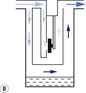
1. The first (Figs 3.6A and B) consists of two dissimilar metals or alloys placed back to back (i.e. a bi-metallic strip). As the two metals have different rates of expansion and contraction with temperature, the device has the ability to ‘bend’. It can, therefore, be used to vary the degree of occlusion in the aperture of a gas channel (usually the bypass) and thus alter the flow of carrier gasses through it.
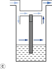
2. In the second arrangement (Figs 3.6C and D), the bi-metallic device consists of a central rod made of Invar, a metal alloy with a low coefficient of expansion, sitting inside a brass jacket, the top part of which is attached to the roof of the vaporizing chamber. The rod is attached only at the base of the brass jacket, which has a higher coefficient of expansion. The outer surface of the jacket is immersed in liquid anaesthetic agent in the vaporizing chamber. As the aforementioned liquid cools, the brass jacket contracts more than the Invar, which is pushed upwards into the bypass, restricting the flow of bypass gas and increasing the flow of carrier gas through the vaporizing chamber.
Potency of anaesthetic agent
As described above, current anaesthetic vapours are too potent to be administered as saturated vapours and require suitable dilution. Therefore, only a proportion of the gas intended for the patient is diverted in the vaporizer to collect vapour. This amount may be varied to produce the desired concentration by using an adjustable flow-splitting valve (see Fig. 3.3). This is usually a rotary valve incorporated within the vaporizer outlet. It proportions the flow of gas between the vaporizing chamber and the vaporizer bypass system, thus controlling the final vapour composition (i.e. the more gas going through the vaporizer chamber, the greater the amount of vapour leaving the vaporizer). The flow-splitting valve is calibrated in percentage of the vapour in the final gas/vapour composition. However, this valve is accurate only if the vaporizer is temperature-compensated (see above). As both the temperature-compensating mechanism and the flow-splitting valve work by altering resistance through the vaporizer, the devices are dependent on each other. Therefore, each vaporizer for a designated anaesthetic agent is individually calibrated at the factory (see below) for that agent and for a specific range of temperatures and flow rates of carrier gas.
Volatility
The flow-splitting ratio is dependant on the volatility of the agent. For example, at any given temperature, a very volatile agent will produce a higher saturated vapour pressure than a less volatile agent, even though they may have similar potencies. The former, however, requires a flow-splitting valve with a wider ratio so as to increase the dilution in order to provide a similar concentration. Table 3.1 shows the relative potency and volatility of some liquid anaesthetic agents that influence vaporizer design.
Table 3.1 Relative potency and volatility of some liquid anaesthetic agents
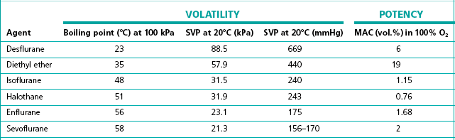
MAC, minimum alveolar concentration;
SVP, saturated vapour pressure
Types of variable bypass vaporizers
Draw-over vaporizers
The early vaporizers relied on the patient’s respiratory effort to draw gas over the vaporizing surface (hence their name). Unfortunately, draw-over systems are subjected to very variable flow rates, i.e. from 0 to 601 min−1 (the peak inspiratory flow in a hyperventilating adult). At these higher flows the carrier gas may fail to pick up a saturated vapour resulting in a reduced concentration leaving the vaporizer. Furthermore, the gas pathways must offer little resistance to flow so as not to compromise the patient’s inspiratory effort. This restricts the design of the vaporizer components, especially the flow-splitting valve (see above), which must have sufficiently wide a bore. It is very difficult to design a flow-splitting valve that will work accurately over a wide range of flow rates, i.e. 1–60 l min−1. As discussed above, the valve must present a low flow resistance so that at flows of 40 l min−1 (the peak flow in a patient breathing spontaneously), no respiratory embarrassment is caused. However, if the flow across this valve drops to about 4 l min−1, the resistance through the valve will be so low that carrier gas will preferentially pass across the bypass channel rather than through the vaporizing chamber where it has to mix with and then push the ‘heavy’ vapour out into the attached breathing system. At this flow and below, there is thus bound to be a marked fall in vaporizer performance.
Factors affecting vaporizer performance
Barometric pressure
Ideally, a vaporizer should also be calibrated at a specific barometric pressure. Strictly speaking, as a saturated vapour is only altered by temperature, one might expect the calibration of a vaporizer to be independent of barometric pressure. However, changes in barometric pressure will affect the carrier gas composition passing through the vaporizer, which in turn will affect the concentration of vapour in the mixture leaving it. For example, when the barometric pressure is reduced (at altitude), the number of molecules of carrier gas flowing through the vaporizer is reduced. However, the number of vapour molecules collected by the gas in the vaporizing chamber remains unchanged, although these now represent a higher percentage of the total number of molecules leaving the vaporizer. The final output concentration of vapour is thus now higher than at sea level, although its partial pressure remains unchanged. As anaesthetic effect is governed by the partial pressure of the agent in the body, there is no effective change under the normal conditions. However, extremes of pressure may have a significant effect. For example, at very high altitude (low barometric pressure), a very volatile liquid such as ether may boil at ambient temperature. This may render the use of such agents difficult. Fig. 3.2 shows the variation of boiling point with atmospheric pressure.
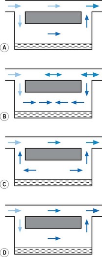
Pumping effect
When a resistance is applied to the outlet of the anaesthetic machine, such as that which occurs when manually assisted inspiration or controlled ventilation is used, there is an intermittent increase in the anaesthetic gas pressure, which is transmitted back to the vaporizer. When this happens, it causes carrier gas within the vaporizer to be compressed. Gas in the outlet is already saturated and, therefore, cannot pick up any more vapour. When the back pressure is released, the expanding carrier gas, which is also saturated with vapour, surges out through both the inlet and outlet of the vaporizer chamber. The gas that leaves the inlet enters the bypass and adds to the vaporizer output to increase in the final vapour output. (Fig. 3.7 demonstrates the sequence of events.)
• increasing the resistance to flow through the vaporizer and bypass so that the carrier gas develops a higher pressure within the vaporizer, so as to reduce the pumping effect. However, the pressure increase due to vaporizer design should be as small as possible as these pressures are transmitted back to the flowmeters, which are calibrated for use at near atmospheric pressure; or
• building an elongated flow passage into either the inlet or outlet of the vaporizer to minimize the effect of surges in pressure (Fig. 3.8).
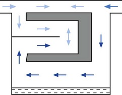
Figure 3.8 Elongation of the inflow channel in a vaporizer preventing saturated vapour reaching the bypass.


