Pearls
- •
Intensivist-operated ultrasound is an important adjunct for vascular procedures at the pediatric intensive care unit bedside and is emerging as an important procedural aid across all percutaneous vascular access applications.
- •
Accuracy of intensivist-operated ultrasound examining the heart, lungs, abdomen, and cerebral circulation has also been explored. Cardiac ultrasound examinations by intensivists demonstrate high sensitivity for pathology similar to studies performed by imaging specialists.
- •
Practice and familiarity with ultrasound’s capabilities, advantages, and disadvantages contribute to responsible and effective practice.
- •
Successful translation of ultrasound from training to clinical practice requires thoughtfully designed processes with regard to protocols, recordkeeping, and quality improvement activities.
Critical care ultrasound has been a topic of exploding interest and impact in the pediatric intensive care unit (PICU), with thousands of citations published yearly on use of ultrasound for diagnostic and procedural applications in the critically ill. Since the 1980s technologic advancements in imaging quality and digital storage have resulted in bedside ultrasound equipment that is both portable and powerful. Its use in the ICU results from recognition of its value for procedure guidance, interaction with cardiac intensivists in specialty ICUs, and shared interest from other clinical specialties, such as emergency medicine. Ultrasound is emerging as standard of care for many ICU procedures and is increasingly recognized as a valuable diagnostic tool. Nonprocedural bedside ultrasound applications performed by intensivists contrasts with traditional diagnostic imaging. It is interpreted at the bedside, occurs synchronously with management decisions, and is repeated as necessary by the bedside clinician for serial assessment. Intensivist-operated examination is more focused on assisting the direct and immediate delivery of care, whereas diagnostic imaging by radiologists and cardiologists emphasizes optimizing study detail. The ability of the intensivist to repeat diagnostic point-of-care studies to evaluate the effect of targeted therapies as a form of monitoring and further guide management decisions emphasizes an additional clinical benefit of this unique technology.
Ultrasound physics and basics of image optimization
The physical principles that make ultrasound possible are well described. Ultrasound energy is transmitted in sound waves through substances at a frequency greater than 20 kHz, beyond the range of human hearing. Probes used for bedside ultrasound typically use frequencies in the range of 1 to 20 MHz or more. Ultrasound impulses are transmitted in a coordinated manner from an array of piezoelectric elements in a transducer aimed at a target of interest. Reflected sound from tissue and interfaces between substances of differing density is received by the same piezoelectric array. Based on known speeds of ultrasound in tissue as well as image processing by the ultrasound device, a two-dimensional image is generated and cycled over time to compose a continuous video or cine. Variability in tissue sound velocity and attenuation properties—including refraction, reflection, absorption, or scattering of returning ultrasound energy—may introduce artifact in images ( Fig. 15.1 ).

A portion of image quality is naturally machine dependent; a variety of parameters are adjustable for image optimization to reduce diagnostic error. Image size modification tools include depth, zoom, and scan area. Though a wide and deep scan area permits capture of a large field of view, short depth or high zoom factor facilitates imaging of small or superficial structures ( Fig. 15.2 ).

Gain is also an important setting for image optimization and can be adjusted in several ways. Gain affects the sensitivity of the machine to returning ultrasound energy. Returning ultrasound energy is attenuated as it passes through tissue. Time to return of reflected ultrasound energy determines depth of visualized structures rendered on the screen. Time-gain compensation settings can be adjusted to emphasize gain at different depths based on when the return signal reaches the transducer. On various machines, these may appear as sliding controls or knobs that control near and far gain. At the bedside, gain is adjusted relative to ambient room lighting so that relevant pathology can be visualized ( Fig. 15.3 ).

Frequency is an adjustable control that also affects image quality. Higher ultrasound frequencies allow for higher-resolution imaging as a function of improved spatial discrimination of structures. Higher frequencies also result in poorer imaging of deep structures owing to signal attenuation. Conversely, lower-frequency imaging can identify deeper structures at the expense of image resolution ( Fig. 15.4 ).

Doppler ultrasound is used in a variety of procedural and diagnostic applications to derive the speed and direction of moving structures in the body, blood flow being a common target. Using color flow Doppler in vascular imaging, ultrasound machines color code areas on the two-dimensional image where tissue and fluid are moving. Returning reflected ultrasound frequency is either Doppler shifted higher (movement toward the transducer) or lower (movement away from the transducer). In the human body, this can correspond not only to blood but also to the motion of effusion fluid and other potential spaces as well. Pulsed wave Doppler samples a small area of the screen for Doppler data that are then plotted along a velocity/time scale ( Fig. 15.5 ). Doppler is most useful when the direction of blood flow is parallel to the ultrasound beam. When flow is not parallel, angle of incidence correction is possible in many commercially available systems. By convention, angle correction is currently not used in echocardiography because of the difficulty in matching beam angles to nonlaminar flows in the heart.

Power Doppler displays amplitude of echoes from moving cells and is less angle dependent than traditional Doppler, thereby permitting improved visualization of vessel branching. For this reason, power Doppler can be a useful modality for vessel identification in procedural guidance.
M-mode ultrasound graphs the received ultrasound signal along a one-dimensional beam over time. This is useful for tracking objects in motion to quantify and characterize their movement ( Fig. 15.6 ). Examples of M-mode applications include assessing respiratory variation of the inferior vena cava (IVC), calculating a left ventricular shortening fraction, and evaluating diaphragmatic excursion. When using M-mode, it is important that the operator’s scanning hand remain motionless because operator movement will be captured on the M-mode tracing as well.

Sweep speed is an important machine setting for M-mode and pulsed wave Doppler when data are plotted against time. Sweep speed is defined as the speed at which the data tracing is graphed on the screen. In some instances a faster sweep speed is necessary to reduce the amount of time displayed on the screen, thereby “stretching” the tracing so that finer details of movement are captured. This is helpful in echocardiography with a tachycardic heart so that cardiac motion is more easily discerned. Conversely, slowing sweep speed may be helpful in compressing more data into one screen ( Fig. 15.7 ). Slowing sweep speed might be necessary for visualizing changes in diaphragmatic motion or changes in arterial flow over a respiratory cycle.

Transducers
Ultrasound transducers appear in a multitude of configurations that serve different specialized functions. They are largely divided into higher-frequency linear array probes and lower-frequency sector type probes, with occasional exceptions.
Linear array transducers are a mainstay of procedural guidance for intensivists and other clinical interventionalists (e.g., interventional radiologists) using ultrasound ( Fig. 15.8 ). They are configured with an array of parallel-oriented piezoelectric elements designed to image a field of tissue below the probe at close proximity to the skin. These probes also tend to emit higher frequencies (7 MHz or above) to visualize the region of interest at high resolution, with some small structure probes operating above 20 MHz. Linear array transducers are optimal for procedural guidance because needle localization is easier with their wide, shallow, and high-resolution field of view. Linear array transducers are also well suited to diagnostic imaging at shallow depths, where higher resolution is preferred. Examples include thoracic imaging and vascular imaging. Linear arrays range in size and shape. In addition to conventional arrays, in which the transducer face forms the end of the handpiece, linear transducers also include hockey stick–shaped vascular probes, originally designed with improved ergonomics for carotid imaging but also useful for peripheral vascular procedures in children.

Sector-type transducers encompass phased array transducers and curvilinear transducers. The sector term refers to the image generated by the concave array appearing as a wedge-shaped sector on the ultrasound screen. Phased array transducers are low-frequency devices and have a small footprint on the skin, designed for deeper wide-field imaging from a small surface on the body ( Fig. 15.9 ). Because these probes are largely used in cardiac imaging, the ultrasound hardware is optimized for a fast frame rate to capture motion at the expense of image resolution. Because of the small footprint and low frequency, these probes are also optimally suited for transcranial imaging for Doppler flow measurements of the cerebral arteries. This type of imaging requires a low fundamental frequency of approximately 1 MHz, with most probes ranging between 1 and 6 MHz. These probes can also be used for diagnostic imaging in the abdomen, particularly in infants and young children.

Curvilinear transducers operate at the same to slightly higher frequency (1–12 MHz) than phased array transducers and are engineered for improved image resolution at the expense of a slower frame rate. For this reason, they excel at looking at relatively nonmobile structures such as the abdomen and its vasculature. Large curvilinear probes are often too large for children; therefore, smaller-radius microconvex curvilinear probes are preferred. These probes are also used for cranial ultrasound in infants owing to their higher frequency and small footprint. Within the ICU, their higher resolution and footprint that is slightly wider than that of a phased array transducer also make them useful for procedure guidance, particularly for vascular access and regional anesthesia. In addition, they may facilitate visualizing the lung and thoracic structures.
Procedural guidance
Venous access
Long before entering the ICU, ultrasound became a mainstay for procedural guidance in interventional procedures. In the hands of intensivists, ultrasound has proved to be a useful adjunct in vascular access, increasing first-pass success and reducing adverse events during central venous catheter (CVC) insertion in a number of large series and meta-analysis of the pediatric literature. Though the majority of ultrasound trials for vascular access have been conducted with trainees likely less familiar with landmark methods for CVC insertion, the preponderance of the primarily adult evidence supporting ultrasound guidance for internal jugular vein CVC cannulation has added ultrasound guidance to the standard of care in this procedure. Although it appears that ultrasound guidance does improve safe vascular access, its use is a skill that requires training and practice. Novice providers should practice procedures with skilled operators before attempting them independently.
Maneuvers for identification of vessel patency are helpful for targeting veins for cannulation. The primary and most reliable method is observing for compressibility of the venous structure and absence of pulsatility. It is important to recognize that patients with pulmonary hypertension can demonstrate pulsatile venous flow that confounds differentiation between vein and artery. Though this finding is most pronounced in patients with a primary diagnosis of severe idiopathic pulmonary hypertension, it can also be seen in patients with acquired pulmonary hypertension from increased intrathoracic pressure or cardiogenic shock.
In the event that compressibility, Doppler flow, or pulsatility cannot identify a venous structure, this may mean that a vessel may no longer be continuous due to sclerosis or thrombosis. Venous thrombi often occupy space in the vessel lumen, obliterate venous flow, and resist external compression. Doppler modalities for identifying vessel occlusion are well described but have limited utility when thrombi are partially occlusive or in shock states when flow is very low.
Various approaches to central vessel cannulation using ultrasound exist. Dynamic (real-time ultrasound visualization) approaches to the central veins include the transverse ( Fig. 15.10 A) or longitudinal ( Fig. 15.10 B) planes relative to the vessel. An advantage of the transverse approach, with the view plane perpendicular to the vessel axis, is that it improves lateral steering of the needle to avoid arterial puncture. A disadvantage is that needle tip identification is harder, because only a cross-section of the needle shaft is visualized. Identification of the needle tip is crucial for successful access and prevention of inadvertent injury; it is performed by sliding the probe and staying over the needle tip throughout the procedure. This sliding technique will help avoid inadvertent puncture of deeper structures (i.e., the pleura or carotid artery in internal jugular venous cannulation). The longitudinal approach, with the view plane parallel to the vessel axis, has reciprocal advantages and disadvantages. It facilitates observation of the advancing needle tip throughout the initial puncture, but it does not provide a view of lateral structures. For these reasons, transverse visualization of the vessels is often more intuitive and most frequently taught to novice practitioners. The static approach uses the ultrasound to identify the vessel, followed by marking of the site for needle puncture without direct ultrasound visualization of the needle during the attempted cannulation. This permits use of both hands for the technical performance of the procedure; however, patient positioning or physiology may change prior to venipuncture, rendering the mark inaccurate. The dynamic approach has been shown to be superior to the static approach.

Though most existing literature focuses on internal jugular venous access, experience with other vessel access using ultrasound guidance has been published. There is limited adult patient experience reported on the placement of CVCs in the subclavian vein. , Ultrasound guidance for subclavian venous access may be stymied by relative probe to patient size issues in pediatric patients. In the longitudinal orientation, the transducer occupies the majority of the skin in the infraclavicular space and limits the area for target insertion. The arc of the subclavian vein through the viewing plane also hampers this method. A number of authors have described a supraclavicular approach to the subclavian or brachiocephalic vein. This approach uses a longitudinal transducer orientation to the vessel and can be limited by space above the clavicle in patients.
Ultrasound guidance for femoral vein CVC placement remains contentious. Existing literature is methodologically limited and includes only small series or series that include femoral cannulation mixed with other catheterization sites. Though data on the efficacy of ultrasound in femoral cannulation is lacking, operator comfort with ultrasound, similar technical performance, and similar complication concerns with the practice of internal jugular cannulation suggest meaningful benefits for ultrasound guidance in the femoral area.
The literature includes few descriptions of central axillary vein CVCs, but this site can be useful for patients with limited options for central access. When inserted in the axillary vein at a position in or distal to the axilla, the catheter takes a similar course to subclavian CVCs. A longer catheter length is necessary so that it reaches from the axilla to the turn of the brachiocephalic vein into the superior vena cava (SVC). In contrast with other CVCs, the redundancy of axillary tissues complicates venipuncture, in which case ultrasound guidance seems especially beneficial.
Arterial and peripheral intravenous access
Outside of central veins, ultrasound has also been useful for peripheral intravenous (IV) access and arterial access. For patients with difficult peripheral access, ultrasound facilitates targeting and site selection, leading to successful IV placement. Ultrasound can identify sites difficult to detect from the surface, particularly collateral vessels that may become engorged owing to obstruction of previously cannulated veins. An important consideration is vessel depth, because deep infiltrates are not as readily recognized as shallow ones, resulting in soft-tissue injury and potential complications. IV catheters exceeding an inch in length are useful to access deeper vessels and to maximize length of catheter within the vascular lumen. Their insertion benefits from placement in veins with sufficiently long straight courses. Deeper vessels require a steeper angle of insertion, which increases the risk of penetrating the back wall of the vessel. Increasing interest in ultrasound guidance has seen a concomitant increase in the production of longer-length catheters by manufacturers, some of which exceed 2.25 inches at the time of this writing. Following the threading of the IV catheter into the vein under ultrasound visualization may help ameliorate this effect, as the operator can keep the device off the back wall of the vessel. For these reasons, IVs deeper than 1 cm from the skin surface are still often riskier candidate vessels.
A number of series have been published on ultrasound guidance for peripheral arterial access. Though historically the arterial pulse has been relied on for arterial catheterization, both adult and pediatric studies , demonstrate that ultrasound guidance using methods similar to venous procedures facilitates arterial access. Recent literature also suggests that ultrasound use mitigates both patient and provider characteristics associated with difficult arterial line placement, demonstrating the technology’s ability to bridge the “experience divide” between those experienced and not with landmark-based techniques.
Ultrasound can also help identify catheter position after CVC placement. Direct visualization of other CVCs in the IVC in addition to umbilical catheters is possible in patients. However, identifying upper extremity CVCs is difficult because views of the superior cavoatrial junction are obstructed by lung artifact in older children and adults. Another technique that has been demonstrated to verify CVC position is use of agitated saline. , Agitated saline is produced by aspirating a small blush of blood (<0.1 mL) into 10 mL of saline and rapidly flushing it between two 10-mL syringes attached to a stopcock connected to the CVC until the saline appears homogenous. At this time, the saline is steadily and promptly flushed into the patient so that the contrast is delivered while an ultrasound probe images the superior or inferior vena cava or the right heart. Agitated saline opacifies vascular structures and indicates continuity of the catheter within the proximal vessel or heart. Failure of the bubbles to appear in the venous space suggests that the catheter is not in the correct vessel. Pitfalls in this technique include slow injection, in which contrast may not reach the heart, and the presence of shunting, which could also diminish return of bubbles to the area being examined with ultrasound. Agitated saline techniques should be used with acceptance that small bubbles might travel into the systemic circulation, where there is a small risk that they could obstruct distal organ perfusion.
Umbilical access
Umbilical access can also be facilitated by ultrasound in neonatal patients who may be in the pediatric ICU for specialized therapies, such as advanced cardiac care or extracorporeal membrane oxygenation. , Umbilical catheters can be placed using sagittal positioning of a small curvilinear or phased array transducer over the IVC as it enters the right atrium. Confirmation of tip position at the IVC–right ventricular (RV) junction is possible using this method because catheters are echogenic. This technique can be employed in umbilical arterial catheter placement by identifying the catheter in the descending aorta at the level of the diaphragm.
Drainage procedures
Ultrasound is a useful adjunct to thoracentesis and thoracostomy. Pleural fluid collection is highly amenable to ultrasound interrogation. Simple effusions appear as an enclosed dark anechoic space sharply differentiated from surrounding tissues and often with underlying consolidated lung appearing to float within the fluid. Ultrasound is useful for characterizing effusion complexity: proteinaceous septations and debris appear echogenic within the effusion.
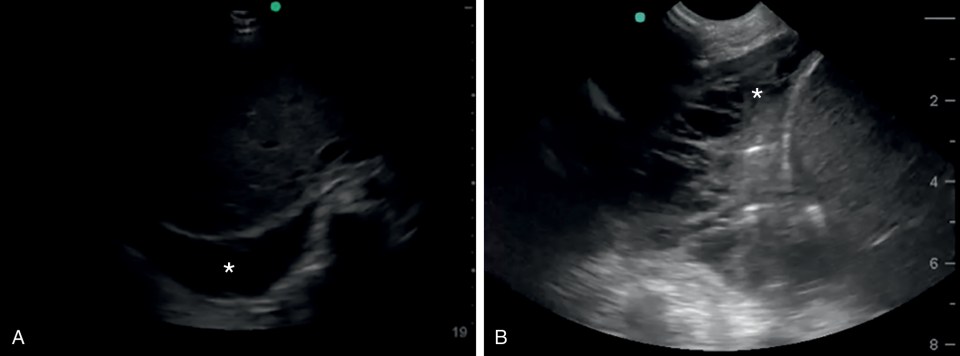
Effusions can be visualized from several locations. During a pleural examination, using a linear array, effusions are recognizable as a dark anechoic space below the parietal pleura. Effusion can also be seen on echocardiographic views, particularly those capturing the dependent areas of the lower thorax, such as subcostal or apical views ( Fig. 15.11 A). Pleural effusion can also be seen in abdominal examinations of the right and left upper quadrant if the view captures the posterior aspects of the diaphragm. In these cases, the effusion appears as an anechoic space cephalad to the diaphragm. An advantage of imaging an effusion using a phased array or curvilinear probe is that a large portion of the effusion tends to be visible in the far field of the sonographic sector, allowing identification of a deep effusion pocket, its extent, and its complexity ( Fig. 15.11 B). Color Doppler ultrasound may assist with effusion identification because its motion within the potential space will be detectable.
Pleural fluid collections can be easily targeted for drainage using ultrasound to ensure safe needle insertion above the diaphragm. Though dynamic (i.e., real-time) ultrasound guidance can be used during the drainage of an effusion, the static technique (i.e., marking the location for needle insertion) simplifies the procedure without exposing the patient to increased procedural risk. There is presently no pediatric evidence to suggest clear superiority of one technique over another, though an adult study demonstrated a reduction in complications (e.g., pneumothoraces) when using the dynamic technique compared with the static technique.
Thoracostomy tubes can also be identified in the effusion space, but they are less visible once fluid is drained. Prior to attachment of a thoracostomy tube to suction, visualization of the effusion space and position of the chest tube within can sometimes help in determining whether the tube travels anterior or posterior to the lung.
Abdominal fluid collections are also characterized as simple or complex, and drainage of the peritoneal space is possible using ultrasound guidance. An important consideration in performing paracentesis is locating and avoiding the inferior epigastric arteries traveling from the external iliac arteries cephalad along the inside of the anterior abdominal wall at the lateral edge of the rectus abdominis muscle. These vessels are identifiable on ultrasound and the machine can assist in planning a safe needle insertion.
With ultrasound, paracentesis is most easily performed from the lateral approach. After appropriately preparing the patient and identifying fluid for drainage, the arteries are identified. Rather than performing a traditional z-track entry, the needle can be introduced obliquely into the peritoneal cavity with the probe oriented longitudinally over the needle for dynamic guidance ( Fig. 15.12 ). The oblique track helps reduce the chance of leakage, is easier under ultrasound than the z-track, and allows direct visualization of needle entry into the peritoneum to avoid underlying solid and hollow organ puncture. A temporary catheter can then be placed using the Seldinger technique for either one-time or ongoing drainage of ascites fluid.

Lumbar puncture
Ultrasound-guided lumbar puncture provides a limited advantage over landmark-based techniques in children as demonstrated in the literature, , though some hypothesize that it is beneficial in patients who have difficult landmarks, such as older and obese patients and children with spine abnormalities (e.g., scoliosis). Such patients can benefit from ultrasound-guided lumbar puncture due to difficulty in determining surface landmarks and insertion depth secondary to lumbar muscularity or adipose tissue. The technique can be performed under ultrasound visualization, but owing to the near-perpendicular angle of needle insertion into the skin as well as reduced ability to directly visualize the dura, subarachnoid space, and spinal cord as children age, the procedure is often best performed under static guidance using insertion markings ( Fig. 15.13 ). This process involves visualizing the spine in two planes, both sagittally along the spine to identify the appropriate entry level and axially (transversely) across it to center insertion in the midline. Views of the spine can also be used for measuring angle and depth of needle insertion to reach the dural space so that an appropriate needle can be selected.

Diagnostic modalities
Pulmonary ultrasound
Historically, pulmonary ultrasound has been considered impractical owing to air-filled alveoli impeding ultrasound transmission. Yet ultrasound images are produced within the thoracic cavity by the complex interaction of the ultrasound beam with interfaces between air- and water-filled structures. Seminal work done by intensivists examining the lungs of critically ill adults and children led to descriptions of pulmonary artifact patterns that reflect lung pathology.
Age can affect visualization of the thoracic cavity in the pediatric patient. Infants have excellent windows for thoracic visualization because of shallow imaging depths to reach the pleural space, higher body water content, and limited thoracic cage ossification. As children get older, their imaging windows may become more difficult as a result of development, including increasing ossification and decreasing body water content, though imaging windows remain largely accessible. If areas of the pleura are difficult to visualize owing to ribs, rotating the probe parallel to the ribs within the intercostal space can improve the view. Lung motion is still appreciated as artifacts across the pleural plane. Alternatively, a microconvex or phased array transducer can be used to see the pleural line, though these lower-frequency probes often perform better in evaluating deep structures.
Thoracic ultrasound of the pleural space identifies overlying skin and soft tissue nearest to the probe, followed by deeper rib and intercostal structures, and then the pleural space. The visceral pleura slides against the parietal pleura through a thin and often invisible layer of normal pleural fluid.
Though the exact physiologic mechanisms for ultrasound lung artifacts is often unclear, their similarity to the artifacts associated with pathology in other organ systems suggest their origins. Reverberation artifacts that replicate the pleural line at regular intervals from proximal to distal field are called A-lines. These can appear regardless of pathology or whether tissue or air is underlying the parietal pleura; therefore, they need only be recognized as artifacts in the image. B-lines and Z-lines are generated radially from interfaces near the pleural line and appear to pierce through the lung parenchyma. B-lines reach the end of the viewable sector and obliterate A-lines, whereas Z-lines are limited reverberatory extensions from the pleural line ( Fig. 15.14 ).

A pattern of increased B-lines suggests increased interstitial lung water. In the adult population, this is consistent with pulmonary edema. It is reasonable to infer that it would bear similar implication in children. However, studies also suggest that B-lines indicate the presence of neonatal respiratory distress syndrome or transient tachypnea of the newborn in the neonatal intensive care setting as well as bronchiolitis in children in the emergency department (ED) setting. Further elucidation of the significance of B-line patterns in critically ill children is lacking.
B-lines in children may also represent lung consolidation. Consolidated lung appears increasingly granular with the appearance of liver-like parenchyma, commonly referred to as hepatization owing to the augmented visibility of consolidated lung parenchyma and vascular architecture appearing similar to hepatic structures. In the case of infectious pneumonia, diffuse geographic areas of consolidation, air, and necrosis may develop, resulting in what some authors term the shred sign. The diagnostic value of these lung consolidation patterns in critically ill children has not been well quantified to date.
Identification of pneumothorax with ultrasound has been described as a dissociation of the visceral from parietal pleura by ultrasound-obstructing air, such that the parietal pleura is no longer visible ( Fig. 15.15 ). Loss of pleural sliding is indicative of pneumothorax; identification of the limit of a pneumothorax as the point where pleural sliding abuts an area where it is absent is described as the lung point . Identification of the lung point is highly specific for pneumothorax. M-mode ultrasound is also useful for identification of pneumothorax. Placement of the M-mode cursor through the pleural surface characterizes movement of the lung parenchyma as a granular-textured echogenic area distal to the pleural line. In contrast with the more horizontal linear pattern of the proximal chest wall, this assumes a seashore-like appearance ( Fig. 15.15 B). When the M-mode cursor overlays pneumothorax, no lung parenchyma movement is seen, and the entire M-mode tracing over time appears to be a pattern of horizontal lines, otherwise described as a barcode or stratosphere sign ( Fig. 15.15 D). Bedside ultrasound used to detect pneumothorax among high-risk neonates has been shown to be highly accurate and timely.

Ultrasound views of diaphragm movement can confirm tracheal placement of an endotracheal tube (ETT) during intubation. This is potentially useful in the management of a ventilated patient requiring rapid confirmation of tracheal placement, such as in the case of a difficult airway patient for whom removal of the tube and reintubation could be dangerous. In this instance, subcostal views of the diaphragm capturing motion of each leaflet while the patient receives positive-pressure breaths can be performed ( Fig. 15.16 ). Confirmation that at least one leaflet moves with large positive-pressure breaths will help verify that the tube is in the airway. Lack of excursion on one side might suggest main-stem bronchus occlusion from secretions or inadvertent main-stem bronchial intubation of the contralateral lung. This technique has been used to confirm tube placement in the operating theater as well as in the pediatric ED. In the neonatal population the tube is visualized within the trachea in the sagittal plane from the parasternal view typically used for evaluation of the aortic arch and pulmonary arteries. Dennington and colleagues were able to accurately gauge depth of ETT position in neonates with high accuracy. In larger infants and older children, this technique has not been successful owing to thoracic growth and ossification.

Airway ultrasound to visualize tracheal stenosis and appropriate ETT fit have also been described, though this is still an exploratory application since it depends on successful identification of the ETT, cuff, and potential areas of stenosis using ultrasound in the air-filled trachea. The accuracy of this technique is still wanting of larger-scale population studies. Some authors have described use of saline to aid in visualization, though there is the potential risk of damaging the cuff in this application. Airway ultrasound is readily performed at the level of the larynx or mid-trachea ( Fig. 15.17 ) with fair visualization of laryngeal structures. Emerging applications for this modality, in addition to ETT sizing and assessment of tracheal caliber, include identification of vocal cord paresis, identification of landmarks for cricothyroidotomy, assessment of esophageal intubation, and identification of structures for transcutaneous injection, among others.

Use of bedside ultrasound to assess diaphragm paresis has also been described. Assessment of spontaneous diaphragm excursion using ultrasound in the oblique coronal (described previously) or sagittal planes accurately demonstrates diaphragm paresis. This technique is also likely useful for patients with diaphragm paralysis from a variety of causes, including protracted neuromuscular blockade or intrinsic neuromuscular dysfunction. Emerging literature also recognizes pediatric diaphragmatic atrophy with intubation and mechanical ventilation similar to changes seen in adult critically ill patients. In adults, such changes in diaphragm thickness have been associated with extubation failure and increased mortality; such associations have not been confirmed in pediatric patient populations.
Abdominal ultrasound
Assessment of abdominal pathology is frequently confounded by nonspecific complaints, particularly in sedated patients. Ultrasound as a noninvasive technology has potential for evaluating abdominal pathology without the radiation exposure of computed tomography (CT). However, as is the case with pulmonary pathology, air within the abdominal cavity creates challenging obstacles to ultrasound interrogation. When air causes artifacts, determining whether the air is within the peritoneum or in the bowel is difficult and is a limitation of abdominal ultrasonography. Air localized within the liver vasculature and bowel wall hypervascularity have been associated with necrotizing enterocolitis in the at-risk neonate.
Similarly, fluid in the abdomen can appear within or outside the intestinal lumen. The normal appearance of air artifact and stool is absent in fluid-filled ileus, resulting in ultrasound visualization of distended, anechoic bowel loops. Peritoneal fluid as a result of ascites, hemorrhage, or peritoneal dialysis fluid is commonly seen in acute care settings. A focused assessment with sonography in trauma (FAST) is performed in four abdominal windows where dependent fluid could appear from a traumatic injury. The probe is usually a curvilinear or phased array transducer. The FAST examination is widely used in adult trauma resuscitation for identification of intraperitoneal fluid, likely either from hemorrhage or ruptured viscus. Large-scale efficacy studies and meta-analyses have reduced initial enthusiasm for the test, citing inadequate specificity, operator and patient variability, and debatable impact on imaging with abdominal CT or patient outcome as major vulnerabilities. In children, the sensitivity of the test is as poor as 52% in some series ; thus, its influence on changing management has been questioned. Meta-analyses published by the Cochrane library suggest similar concerns about the FAST examination for adult patients as well. , When seen, anechoic (dark) fluid in the abdomen may indicate intraperitoneal injury. However, solid-organ injury may result in small to no detectable fluid. It is also important to note that the diagnostic characteristics of the FAST examination in the ED are commonly performed without any elevation of the upper torso. When the torso is elevated in the ICU setting, fluid will likely settle in the more dependent lower quadrants of the abdomen. The FAST examination is commonly referred to as the focused assessment for free fluid when fluid is suspected and assessed using ultrasound in nontrauma patients.
Right upper quadrant ( fig. 15.18 a)
The hepatorenal recess (Morison pouch) is the most dependent part of the peritoneum in the supine patient—which, again, can change with repositioning of the patient. Fluid can be seen between the retroperitoneal kidney and the intraperitoneal liver or above the liver as well. The transducer is placed near or below the lower ribs of the thorax in the posterior axillary line to visualize the right kidney, with the indicator directed toward the patient’s head. Fluid in the Morison pouch, inferior pole of the kidney, or the perihepatic space suggests intraperitoneal injury. The diaphragm is also seen in this view, and pleural effusion or intrathoracic hemorrhage in the trauma setting can also be identified or suspected when a classic mirror artifact of the liver due to the diaphragm is not visualized. The probe is usually oriented coronally but can be oriented axially with respect to the patient; thus, the entire organ should be scanned. If views from the posterior axillary line are difficult, the right kidney can be visualized in the anterior sagittal plane by placing the transducer at the lower edge of the costal margin just lateral to the midclavicular line with the indicator pointed toward the patient’s head. In this view, the Morison pouch can be visualized through the liver.


