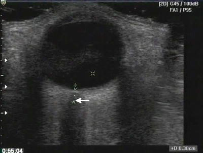
Fig. 22.1
Dark or anechoic fluid surrounds the relatively echogenic lung
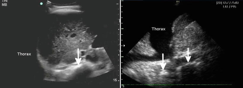
Fig. 22.2
The left image shows an ultrasound with no fluid in the chest; the spine seems to end at the diaphragm and cannot be traced further (arrow). The right image shows a collection of fluid in the chest, with the spine continuing above the diaphragm (arrows)
Pneumothorax
One of the most popular and clinically useful advanced trauma ultrasound applications is the detection and exclusion of pneumothorax. The basis for this application is that ultrasound can detect the back-and-forth movement of the visceral and parietal pleura occurring during lung expansion and contraction, something that should be present in spontaneously breathing and ventilated patients. While ultrasound does not detail lung parenchyma in the healthy lung, it does show the pleural line, without distinguishing visceral from parietal pleura (Fig. 22.3). In order to visualize the movement of the layers past each other, known as the sliding lung sign (SLS), both the visceral and parietal pleura must be imaged. However, when air is present between the layers as in the case of a pneumothorax, it blocks diagnostic ultrasound from imaging the visceral pleura since medical ultrasound is not transmitted through air [22, 23]. Thus, when air is present between the visceral and parietal pleura, ultrasound shows loss of the sliding lung sign. Confirmation of lung sliding can be verified using M-mode. The area under investigation, between the rib shadows, is centered in the screen, while M-mode is initiated after aligning the vertical line through the area in question. The “barcode sign” or “stratosphere sign” is the appearance of parallel horizontal lines extending through the entire field in view, which indicates the lack of normal motion of an inflated lung on M-mode (Fig. 22.4). While the lack of lung sliding is not specific for pneumothorax, the presence of the lung sliding sign effectively rules out pneumothorax at the intercostal locations under the applied ultrasound probe. The sensitivity and specificity of this sign has varied significantly in multiple studies. Reported values have ranged from 40 to 99 % and 60 to 100 % for sensitivity and specificity, respectively [24–28].
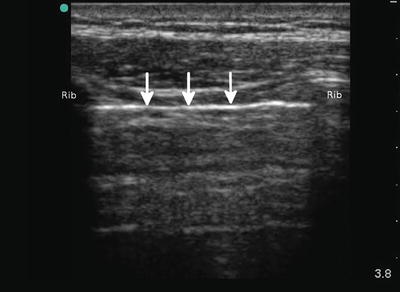
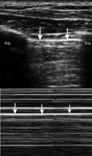
Fig. 22.3
The white line (arrows) in between the ribs is the pleural line; the visceral and parietal pleura cannot be distinguished
Fig. 22.4
The stratosphere or barcode sign. No movement occurs above or below the pleural line on the M-mode tracing as signified by the identical appearance above and below the pleural line (arrows). This occurs as a result of the pneumothorax preventing visualization of the visceral pleura
The lung ultrasound examination was traditionally performed using a rudimentary micro-convex transducer [29]. However, modern lung ultrasound for evaluation of pneumothorax is best performed using a high-resolution linear ultrasound transducer. Such a transducer allows the high-resolution imaging of the pleural interface and enables the sonographer to detect the subtle sliding of the pleural surfaces. Improved imaging can lead to higher confidence when such movement is absent, a problem with earlier ultrasound probes. In the trauma patient, the intrathoracic air will seek the least gravitationally dependent area in the chest. Therefore, if the patient is supine, it should be in the anterior chest. Both sides of the chest should be evaluated. The ultrasound transducer is placed in a sagittal orientation with the indicator pointed cephalad. This allows one to use the ribs as an anatomic landmark (Fig. 22.5). This is important since multiple tissue lines may be present that simulate a pleural line and could be confusing. The pleural line will be just deep to the ribs as noted. In the normal lung, it will be seen moving back and forth, typically disappearing under the bony ribs. This movement will be timed to respirations, not the heart rate. When the lung sliding appears to be stunted, but still present (sometimes described as shimmering), and is timed to the heart rate, it is likely a lung pulse [30]. The lung pulse occurs when no pneumothorax is present to introduce air in between the visceral and parietal pleura. However, if the lung is not ventilated, such as in a misplaced endotracheal tube, the pleural line will appear to pulse, not moving significantly, in time with the heart. The identification of a lung pulse can be coupled with simple deductive reasoning to decide if a main-stem or esophageal intubation is present. If seen unilaterally, a lung pulse should indicate ipsilateral main-stem bronchus intubation or obstruction such as mucous plugging [31]. Absence bilaterally suggests an esophageal intubation or tracheal obstruction. Appropriate correction such as slowly pulling back the endotracheal tube in a main-stem intubation can be tracked in real time by observing the disappearance of a unilateral lung pulse as the tube is pulled back.
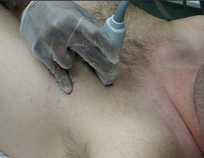
Fig. 22.5
The ultrasound transducer is in a cephalad orientation resulting in a sagittal scanning plane
While pleural line sliding may be absent not only in cases of pneumothorax, given a clinical setting where PTX is high in the differential, an absent SLS may be critical for clinical decision-making. Pathologic processes that may eliminate the SLS also include pneumonia; COPD, especially bullae formation; and others. A near pathognomonic finding for PTX is the lung point [32]. The lung point is literally the intersection of normal lung with free intrathoracic air or PTX. Additionally, other artifacts from the pleura such as echogenic B lines may be seen sliding in and out as the normal lung moves in and out of view [32]. While several pitfalls with this finding can be seen to include the edge of the heart, diaphragm, and contused lung, careful scanning and awareness of nearby anatomy make this sign almost 100 % specific [33]. It is important to note that as a PTX increases in size, the lung point will become more lateral and posterior in a supine patient and then disappear completely as no visceral pleura can be seen contacting the parietal pleura anywhere along the thoracic wall (Fig. 22.6).
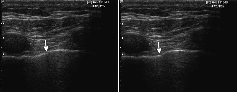
Fig. 22.6
A lung point is demonstrated, with pleural sliding and aerated lung on the left side of the screen and the beginning of the pneumothorax or intrapleural air on the right. The left image lung point is in a different location than the right image (arrow depicts its leading edge). The lung point location changes with respiration
Resuscitation and Volume Status
Adding a view of the inferior vena cava to the cardiac assessment allows the operator to assess patient volume status and potentially rates of blood loss [34–38]. While not without controversy, since the IVC diameter and collapsibility are well-proven monitors of volume status in its extremes (such as significant collapse or greater than 2 cm dilation with no variation), it is a reasonable adjunct in the trauma patient. Studies of dehydrated or volume-depleted patients have shown that an IVC that collapses completely with normal respiration is an indicator of low intravascular volume and also low central venous pressure (Fig. 22.7). Inversely, a dilated, non-varying IVC that is greater than 2 cm in diameter measured 2 cm distal to the confluence of the hepatic veins into the IVC suggests fluid overload and increased central venous pressures. In trauma patients, it is the flat, completely collapsing IVC that is likely to be of greatest concern. This is especially useful in cases where blood loss may be suspected but cannot be proven in an unstable patient. One study suggested that as little as 450 cc of blood removed over 5 min may be detected by serial IVC measurements [38]. However, other studies have called this into question [39]. None of the studies, either pro or con, have had the power to settle the argument [40]. However, the principle is potentially useful. One should be cautious, however, as this assessment may become less accurate in patients on positive pressure ventilation as the elevated intrathoracic pressures may mask the IVC variability.
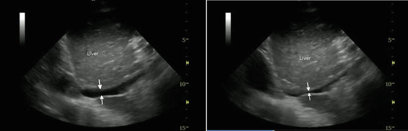
Fig. 22.7
The left image shows an IVC prior to a normal inspiration; it does not appear significantly collapsed (arrows). The right image shows a significant collapse of the IVC with respiration. With deep breath, the IVC could not be visualized due to flattening
Musculoskeletal Ultrasound
In terms of clinical logistics, our research group has recently launched the holistic approach (HOLA) concept of critical care ultrasound (CCU) imaging. We have envisioned HOLA-CCU as part of the patient examination by a clinician to visualize all or any parts of the body, tissues, organs, and systems in their live, anatomically and functionally interconnected state and in the context of the whole patient’s clinical circumstances [40]. In that sense, any ultrasound view obtained through the skin contains some information about soft tissues. While serving as imaging window and anatomical reference structures in focused techniques (e.g., the chest wall in lung scanning), soft tissues themselves are often a primary target (e.g., in extremity injury). This is particularly true regarding musculoskeletal (MSK) ultrasound scanning [41, 42]. Ultrasound in MSK evaluation is well established and not surprisingly has been adopted for trauma patient evaluation as well. High-resolution ultrasound imaging through the use of linear array transducers allows a detailed look at the cortex of long bones, ribs, and other structures. Since nearly all fractures should involve some sort of cortical disruption, a highly magnified look at the cortex is ideal for detecting fractures. In trauma cases, some of the long bones sought may be quite deep and curved abdominal transducers may need to be utilized to image the femur, especially in large patients. Already present at the patient bedside, ultrasound allows detection of fractures such as the one seen here in the femoral shaft of a motor vehicle accident patient (Fig. 22.8).
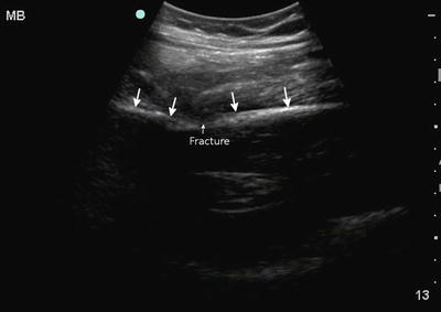
Fig. 22.8
A disruption is seen in the cortical continuity of the femur in this femoral shaft fracture. Notice the change in angle (arrows) of the femoral shaft
Bony cortex is seen as a bright echogenic line, typically linear. The ultrasound examination should be performed in at least two orthogonal planes as with any organ of interest. Especially with bones such as the radius and ulna, one axis may appear grossly normal, while the orthogonal one shows a step-off, suggesting a fracture that can be investigated more closely. Typically a long bone is imaged in its longitudinal and transverse axes. In the short axis, a long bone such as the humerus or femur will be curved while the tibia will be relatively flat. The key is to focus on any cortical disruptions. The operator must take the patient’s age into account and avoid mistaking growth plate regions for fractures. One of the single most useful aspects about MSK ultrasound is that a normal comparison is almost always readily available in the form of the contralateral limb or side of the torso. Apart from bone pathology, ultrasound has the potential to detect muscle, tendon, and soft tissue pathology in trauma victims. Acute muscle contusion and hemorrhage appear hyperechoic, while later stages of injury exhibit mixed patterns. Partial or complete musculotendinous tears with or without retraction are usually obvious. Intramuscular hematomas may later evolve into seromas or intramuscular cysts (anechoic fluid collections) that may require aspiration or surgical drainage. Hypoechoic muscular swelling with architectural disorganization may be observed in traumatic rhabdomyolysis.
In crush injuries, ultrasound can assist in critical decision-making and have extremity and lifesaving significance, since a buildup of pressure within the fascial compartment disrupts tissue perfusion (compartment syndrome) with dire consequences, unless fasciotomy is emergently performed. An advanced HOLA protocol in extremity crush injuries could include assessment of: (a) the shape and structure of all the fascial compartments (looking for outward convexity of the normally flat fascial partitions between compartments), fractures, tears, hematomas, and hypoechoic areas of potential fluid collection or necrosis; (b) color and pulsed-wave Doppler monitoring of the vessels within the compartment and the main artery feeding the compartment; (c) renal imaging (monitoring of size/volume, renal arterial spectral Doppler, and parenchymal differentiation); and (d) search for free abdominal fluid if the thigh and pelvis areas are involved.
Head Trauma
Ultrasound in head trauma offers surprising utility. The same MSK applications described above apply to the skull and remarkable detail can be noted such as small disruptions in the smooth bony cortex. Any disruption in the cortex or step-off may be a skull fracture line. Evaluation in two orthogonal planes will help better define the area in question. Suture lines are a potential for confusion but some practice like scanning the normal skull will help the sonologist to become familiar with their appearance. Additionally, most skull fractures will be associated with an overlying soft tissue hematoma [43]. In children, suture lines, especially partially closed ones and fontanels, may present additional challenges. However, known anatomic locations and the ability to trace the suture line and evaluate any skull fractures in two orthogonal planes allow one to differentiate between a traumatic injury and normal anatomy. Facial fractures can also be detected using a linear array transducer but require more experience. Again, the sonologist looks for cortical disruptions of facial bones and compares the injured and uninjured side whenever possible. The ultrasound literature contains studies documenting ultrasound’s high accuracy in the evaluation of the sinuses and blood-filled sinuses, orbital air, and a multitude of other injuries that can be diagnosed with sufficient skill [44–46].
There is additional utility to ultrasound in estimating and tracking the intracranial pressure (ICP). While direct visualization of brain injury in the adult is rarely possible with ultrasound, a secondary marker of significant (although sometimes still nonoperative) brain injury is the elevation in the ICP. When significant brain injury results from trauma, it is typically associated with some level of elevation in ICP. With a large intracranial hemorrhage, this may be a marked elevation, while with a smaller one, the elevation is relatively minor. Dating back to the 1960s, researchers realized the spinal fluid bathing the optic nerve inside the optic nerve sheath communicated directly with the ventricles [47]. Any rise in ICP from the ventricles was noted almost instantaneously in the optic nerve sheath. Being a distensible structure, the sheath dilates in a somewhat predictable fashion. Multiple studies have evaluated the utility of measuring the optic nerve sheath diameter (ONSD) in trauma and other patients [48]. The main challenges are careful technique and interoperator reliability. Due to the relatively small size changes involved, precise measurements are required. However, a recent meta-analysis suggested ONSD measurement had utility in predicting elevated ICP and in trauma suggesting intracranial injury [49]. While CT may be the common test of choice in most trauma settings, it is not ubiquitously available in all locations and is very expensive. During transport and for serial monitoring, ONSD measurement through ocular ultrasound holds considerable promise and utility in the right clinical context until other technologies are developed that are also noninvasive and affordable but largely user independent.
To perform an ONSD measurement, a linear ultrasound transducer is the probe of choice and the scan is performed through a closed lid. Both eyes should be scanned when possible for comparison. A large amount of gel is placed in the orbit for good coupling but also to avoid any pressure on the eye. In the ideal technique, the ultrasound screen will show an obvious anechoic stripe at the top of the screen signifying the presence of gel between the transducer and the eyelid. While sophisticated equipment may be able to measure some transmission of pressure through ultrasound gel, it is not of any physical significance. Sterile gel can be used and is widely available in small lubricant packets in clinical settings. Wiping off the gel has to occur with great care to avoid pressing on the globe if ocular injury is suspected or noted on ultrasound. As an aside, ultrasound is superb at detecting several ocular injuries such as lens displacement, globe rupture, retinal detachments, and vitreous bleeding. However, the optic nerve is the goal of this examination and is visualized just posterior to the globe. The ideal for simple measurement of the ONSD is to obtain a clear image of the optic nerve as it travels posterior from the globe. Measured at approximately 3 mm posterior to the globe, the internal diameter should be obtained several times and averaged (Fig. 22.9). A meta-analysis suggested that using a cutoff value around 5.8 mm may be reasonable [49]. Our group has recently suggested new quality criteria for sonographic ONSD measurements which are summarized below: