KEY POINTS
1. The majority of cardiac surgical transesophageal echocardiography (TEE) imaging uses 2-dimensions, which is accomplished via phased array transducers consisting of 64 to 128 small crystals activated sequentially.
2. Pulsed-wave Doppler (PWD) profiles blood flow velocity at a single point along the ultrasound beam, whereas continuous-wave Doppler (CWD) detects the maximum velocity profile along the full length of the ultrasound beam. CWD permits measurement of higher-velocity blood flows (e.g., aortic stenosis) than PWD.
3. Color-flow Doppler (CFD) is a form of PWD that superimposes velocity information onto a 2D image, which assesses blood flow direction when it is predominantly moving either toward or away from the transducer.
4. Before placing a TEE probe, significant esophageal pathology should be ruled out by asking the patient about swallowing difficulty and about known esophageal dysfunction.
5. Global and regional left ventricular systolic and diastolic function can be assessed qualitatively or quantitatively using TEE, as can left ventricular preload (end-diastolic volume). Wall motion can be graded on a scale of 1 (normal) to 5 (dyskinesis).
6. A comprehensive TEE examination typically involves 20 standard views, which are shown in Figure 5.2.
7. Several TEE modalities can be used to assess mitral regurgitation, the easiest way being CFD.
8. Aortic stenosis can be assessed using a variety of TEE modalities including imaging in several planes, planimetry in a short-axis view to trace aortic valve area (AVA), and AVA assessment by continuity equation.
9. TEE is useful for interrogating the proximal ascending aorta, the aortic arch, and the descending aorta, but it has a “blind spot” for the distal ascending aorta that requires epiaortic echocardiography for diagnostic interrogation. Complete thoracic aortic interrogation is important in the presence of advanced aortic arteriosclerosis and aortic dissection.
10. TEE assessment of new left ventricular regional wall motion abnormalities is the most sensitive bedside monitor of myocardial ischemia.
11. TEE is highly sensitive for detecting intracardiac air.
12. Intraoperative TEE is indispensable during surgery for cardiac valve repair or replacement and for ventricular assist device placement.
13. Real-time 3D TEE shows promise especially in intraoperative assessment of operations for mitral valve disease and congenital heart disease.

I. Basic principles of ultrasound imaging
Medical ultrasound is produced by a piezoelectric crystal that vibrates in response to a high-frequency, alternating electrical current. The same crystal is deformed by returning echoes producing an electrical signal that is detected by the instrument. Ultrasound transmitted from the transducer into the patient interacts with the tissues in four ways: (i) Reflection, (ii) refraction, (iii) scattering, and (iv) attenuation. Ultrasound is reflected when it encounters the interface between tissues of different acoustic impedance, primarily a function of tissue density, and the timing, intensity, and phase of these echoes are processed to form the image. The velocity of transmission of ultrasound through soft tissues is relatively constant (1,540 m/s), and the time it takes the waves to travel to an object, be reflected, and return is determined by its distance from the transducer. Selecting the frequency of an ultrasound transducer is a trade-off between image resolution and depth of penetration. Higher frequencies have better resolution than lower frequencies, but they do not penetrate as far into tissue. The frequency of the ultrasound used in transesophageal echocardiography (TEE) typically ranges from 3.5 to 7 million cycles per second (MHz).
II. Basic principles of Doppler echocardiography
A. Doppler echocardiography uses ultrasound scattered from blood cells to measure the velocity and direction of blood flow. The Doppler effect increases the frequency of waves scattered from cells moving toward the transducer and decreases the frequency of waves from cells moving away. This change in the transmitted frequency (FT) and the scattered frequency (FS) is called Doppler shift (FS − FT) and is related to the velocity of blood flow (V ) by the Doppler equation:

where c is the speed of sound in blood (1,540 m/s) and q is the angle between the direction of blood flow and the ultrasound beam. The 2 in the denominator corrects for the time it takes the ultrasound to travel to and from the blood cells. In order to get a reasonably accurate (less than 6% error) measurement of blood velocity with Doppler echocardiography, the angle between the flow and the ultrasound beam (q) should be less than 20 degrees.
B. The Bernoulli equation describes the relationship between the flow velocity through a stenosis and the pressure gradient across the stenosis. It is a complex relationship that includes factors for convective acceleration, flow acceleration, and viscous resistance. In certain clinical applications, such as aortic and mitral stenosis, a simplified form may be used. The simplified Bernoulli equation is:
ΔP = 4V2
where ΔP is the pressure gradient in millimeters of mercury (mm Hg) and V is the velocity in meters per second (m/s). The simplified Bernoulli equation should only be used in applications validated against another gold standard.
III. Modes of cardiac ultrasound imaging
A. M-mode echocardiography was the primary imaging mode for echocardiography for many years before the development of two-dimensional (2D) imaging in the late 1970s. It directs pulses of a single, linear beam of ultrasound into the tissues and displays the distance from the transducer of the returning echoes on the y-axis of a graph with signal strength indicated by brightness. The x-axis of the graph shows time, and motion of the structures is seen as curved lines. M-mode is useful for precisely timing events within the cardiac cycle. Its other advantage is very high temporal resolution, making thousands of images per second, which allows detection of high-frequency oscillating motion, such as vibrating vegetations.
1
B. Two-dimensional echocardiography is made by very rapidly moving the ultrasound beam through a plane, creating multiple scan lines that are displayed simultaneously to construct a 2D tomographic image. Mechanical transducers accomplish this by physically rotating or oscillating the crystal. However, TEE probes usually have phased-array transducers, which consist of an array of many (64 to 128) small crystals that are electrically activated in sequence to move the beam through the imaging plane. The number of 2D images that can be formed each second is called frame rate (temporal resolution), which is determined by the width (number of scan lines per image) and depth (time for each pulse to return) of the imaging sector. Typical frame rates for 2D echocardiography are 30 to 60 frames per second, which is fast enough to accurately reflect most motion in the heart.
2
C. Pulsed-wave Doppler (PWD) measures the velocity and direction of blood flow in a specific location, called sample volume, which can be placed by the user in the area of interest of a 2D image. The velocity of flow is displayed with time on the x-axis and velocity on the y-axis. Velocities going toward the transducer are above the baseline of the y-axis and velocities away from the transducer below the baseline. PWD uses one transducer to both send and receive signals, determining the depth of the sample volume from the transducer by listening at a predetermined interval after transmission. This limits the maximum rate at which pulses can be sent (pulse repetition frequency), which in turn limits the maximum Doppler shift (Nyquist limit) and the blood velocity that can be measured with PWD. The farther the sample volume is from the transducer, the lower the maximum velocity that can be measured. Typically, velocities more than 1.5 to 2 m/s cannot be measured with PWD.
3
D. Continuous-wave Doppler (CWD) measures the velocity and direction of blood flow along the line of sight of the ultrasound beam. The information is displayed with time on the x-axis and velocity on the y-axis, as with PWD. CWD uses two transducers: One to continuously transmit and the other to continuously receive. As a result, all returning signals are superimposed on the display, so CWD cannot determine the depth from the transducer from which a returning signal originated (range ambiguity), only its direction. But, unlike PWD, CWD has no limit on the maximum velocity measured. CWD is used to measure blood velocity too high for PWD, such as aortic stenosis (AS), and to determine the maximum velocity of a flow profile, such as with mitral stenosis.
E. Color-flow Doppler (CFD) is a form of PWD that superimposes the velocity information onto the simultaneously created 2D image of the heart, allowing the location and timing of flow disturbances to be easily seen. Flow toward the transducer usually is mapped as red and away as blue. Some CFD maps, called variance maps, add green to indicate turbulence in the flow. Since it is a form of PWD, CFD cannot accurately measure higher flow velocities, such as mitral regurgitation (MR) and AS, and these flows appear as a mixture of red and blue, called mosaic pattern. Also, as the flow velocity passes the limit of the CFD velocity scale (Nyquist limit), the color will alias, or change from red to blue or from blue to red, depending on the direction of flow. The aliasing velocity or Nyquist limit for CFD varies with the depth of the color sector, but typically is less than 100 cm/s. Since the instrument must develop both the 2D and Doppler images, the frame rate is lower with CFD than with 2D imaging alone, typically in the range from 12 to 24 frames per second. At frame rates below 15 frames per second, the image becomes noticeably jerky as the eye can discern the individual images. Decreasing the width and depth of the 2D image and the CFD sector within it will increase the frame rate.
F. Tissue Doppler is a form of PWD that measures the velocity of tissue motion at specific points in the myocardium. Its most common application is to measure the velocity of mitral annular motion to assess systolic function of the left ventricle (LV). More sophisticated analysis can be performed between two adjacent points in the myocardium to measure strain (tissue deformation over time) and strain rate (rate of deformation) to assess systolic and diastolic functions in different regions of the LV and the right ventricle (RV). Evaluation of synchrony of ventricular contraction is also possible with tissue Doppler.
IV. Indications for TEE during cardiac surgery
TEE can be used as a diagnostic tool during cardiac surgery to direct the surgical procedure and diagnose unanticipated problems and complications. TEE also is useful to the cardiac anesthesiologist as a monitor of cardiac function. Often, TEE is used for both purposes during heart surgery. The recently revised American Society of Anesthesiologists and the Society of Cardiovascular Anesthesiologists (ASA/SCA) Practice Guidelines for Perioperative TEE state that “For adult patients without contraindications, TEE should be used in all open heart (e.g., valvular procedures) and thoracic aortic surgical procedures and should be considered in coronary artery bypass graft surgeries” [1].
The ACC/AHA 2006 Practice Guidelines for the Management of Patients With Valvular Heart Disease recommend that intraoperative TEE be performed for valve repair surgery, valve replacement surgery with a stentless xenograft, homograft, or autograft valve, and for valve surgery for infective endocarditis. The guidelines also state that intraoperative TEE is reasonable for all patients undergoing cardiac valve surgery [2].
V. Safety, contraindications, and risk of TEE
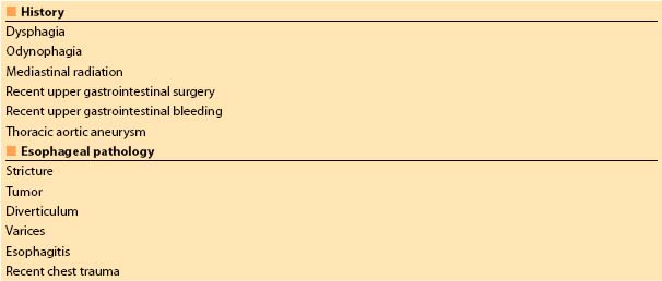
A. Preoperative screening for esophageal disease should be completed before proceeding with TEE. The patient should be interviewed when possible and asked about a history of esophageal disease, dysphagia, and hematemesis. The medical record should be reviewed as well. Relative contraindications to TEE are listed in Table 5.1. The presence of a relative contraindication requires balancing the risk with the importance of TEE to the procedure. In patients with distal esophageal or gastric pathology, it often is possible to obtain the information needed with TEE without advancing into the distal esophagus. Preoperative esophagoscopy is another option to consider when the need for TEE is important and the risk is unclear.
4
Table 5.1 Relative contraindications to transesophageal echocardiography
B. TEE probe insertion and manipulation should be performed gently. The probe must never be forced through a resistance, and excessive force must never be applied to the control wheels.
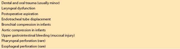
C. Complications of TEE are uncommon in properly screened patients, but they may be serious [3]. Complications of TEE are listed in Table 5.2. Serious injuries may not be apparent at the time of the procedure [4].
Table 5.2 Complications of transesophageal echocardiography
VI. Intraoperative TEE examination
A. Probe insertion is performed after the patient is anesthetized and the endotracheal tube is secured. An orogastric tube is inserted and the contents of the stomach and the esophagus are suctioned. As the mandible is displaced anteriorly, the probe is gently inserted into the posterior pharynx in the midline and advanced into the esophagus. A laryngoscope may be used to displace the mandible and better visualize the esophageal opening if necessary. As the probe is advanced into the thoracic esophagus (approximately 30 cm), the heart should come into view. On rare occasions, the probe cannot be placed in the esophagus, in which case the TEE is abandoned.
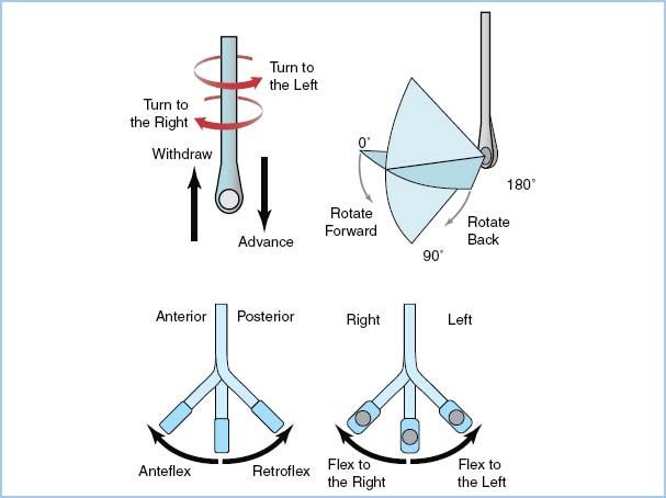
B. Probe manipulation is accomplished by advancing and withdrawing the probe within the esophagus, rotating the probe to the patient’s left (counterclockwise) or right (clockwise). Assuming that the transducer is facing anteriorly (toward the heart), the tip flexes anteriorly and posteriorly with the large control wheel, and flexes to the patient’s right and left (can be envisioned as “wagging,” as in a dog’s tail) with the small control wheel. With a multiplane TEE probe, the angle of the transducer is rotated axially from 0 degrees (horizontal plane), through 90 degrees (vertical plane), to 180 degrees (mirror image of 0 degree horizontal plane) (Fig. 5.1).
Figure 5.1 Terminology used to describe manipulation of the probe and transducer during image acquisition. (From Shanewise JS, Cheung AT, Aronson S, et al. ASE/SCA guidelines for performing a comprehensive intraoperative multiplane transesophageal echocardiography examination: recommendations of the American Society of Echocardiography Council for Intraoperative Echocardiography and the Society of Cardiovascular Anesthesiologists Task Force for Certification in Perioperative Transesophageal Echocardiography. Anesth Analg. 1999;89:870–884, with permission).
C. Machine settings are adjusted to optimize the TEE image. These settings are continuously adjusted by the user as the examination proceeds.
1. Transducer frequency is adjusted to the highest frequency that provides adequate depth of penetration to the structure being examined.
2. Image depth is adjusted to center the structure being examined in the display.
3. Overall image gain and dynamic range (compression) are adjusted so that the blood in the chambers appears nearly black and is distinct from the shades of gray representing tissue.
4. Time gain compensation controls are adjusted so that there is uniform brightness from the near field to the far field of the image.
5. CFD gain is adjusted to a threshold that just eliminates any background noise within the color sector.
D. TEE views. The ASE/SCA Guidelines for performing a comprehensive intraoperative multiplane TEE examination [5] define 20 views that comprise a comprehensive TEE examination (Table 5.3). These 20 views are shown in Figure 5.2. The views are named for the location of the transducer (echocardiographic window), a descriptive term of the imaging plane (e.g., short axis [SAX] or long axis [LAX]), and the major anatomic structure in the view. All of these views can be developed in most patients. Additional views may be needed to completely examine a patient with a particular form of pathology. The sequence in which these views are obtained will vary from examiner to examiner, but it is generally most efficient to develop the midesophageal (ME) views and then the transgastric (TG) views.
Figure 5.2 Twenty cross-sectional views (a. through t.) composing the recommended comprehensive transesophageal echocardiographic examination. Approximate multiplane angle is indicated by the icon adjacent to each view. asc, ascending; AV, aortic valve; desc, descending; LAX, long axis; ME, midesophageal; RV, right ventricle; SAX, short axis; TG, transgastric; UE, upper esophageal. (From Shanewise JS, Cheung AT, Aronson S, et al. ASE/SCA guidelines for performing a comprehensive intraoperative multiplane transesophageal echocardiography-examination: recommendations of the American Society of Echocardiography Council for Intraoperative Echocardiography and the Society of Cardiovascular Anesthesiologists Task Force for Certification in Perioperative Transesophageal Echocardiography. Anesth Analg. 1999;89:870–884, with permission.)
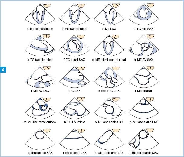
Table 5.3 Recommended transesophageal echocardiographic cross section

1. ME views are developed with the TEE transducer posterior to the left atrium (LA). With a multiplane TEE probe, detailed examinations of cardiac chambers and valves can be completed in most patients from this window alone.
2. TG views are obtained by passing the transducer into the stomach and directing the imaging plane superiorly through the diaphragm to the heart. Images of the LV and right ventricle (RV and the mitral valve (MV) and tricuspid valve (TV) are made from this window. Views to align the Doppler beam parallel to flow through the left ventricular outflow tract (LVOT) and aortic valve (AV) can be developed from the TG window.
3. Upper esophageal (UE) views are made with the transducer at the level of the aortic arch, which is examined in LAX and SAX. In many patients, images of the main pulmonary artery (PA) and pulmonic valve (PV) also may be developed, allowing alignment of the Doppler beam parallel to flow in these structures.
E. Examination of specific structures
1. Left ventricle. The LV is examined with the ME four-chamber, ME two-chamber, ME LAX, TG mid-SAX, and TG two-chamber views.
a. LV size is assessed by measuring the inside diameter at the junction of the basal and mid-thirds at end diastole using the ME two-chamber or TG two-chamber view. Normal is less than 5.4 cm for women and less than 6 cm for men. Normal thickness of the LV wall is 1.2 cm or less at end diastole and is best measured with TEE from the TG mid-SAX view [6].
b. LV global function may be assessed quantitatively or qualitatively. Fractional area change (FAC) is a 2D TEE equivalent of ejection fraction (EF) and is obtained by measuring the LV chamber area in the TG mid-SAX view by tracing the endocardial border to measure the end diastolic area (EDA) and the end systolic area (ESA) and using the formula: FAC = (EDA − ESA)/EDA. Normal FAC is greater than 0.50. This method is not as accurate when wall-motion abnormalities are present in the apex or the base of the LV. Qualitative assessment of LV function is performed by considering all views of the LV and estimating the EF (estimated ejection fraction [EEF]) as normal (EEF greater than 55%), mildly decreased (EEF 45% to 54%), moderately decreased (EEF 35% to 44%), moderately severely decreased (EEF 25% to 34%), or severely decreased (EEF less than 25%). EEF by experienced echocardiographers correlates with nonechocardiographic measures of EF as well or better than quantitative echocardiographic measurements of EF [7].
5
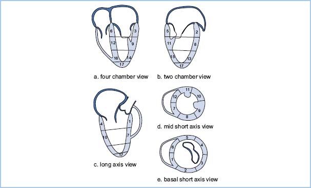
c. Assessment of regional LV function. The LV is divided into 17 regions or segments (Fig. 5.3). Each segment is rated qualitatively for thickening during systole using the following scale: 1 = normal (greater than 30% thickening), 2 = mild hypokinesis (10% to 30% thickening), 3 = severe hypokinesis (less than 10% thickening), 4 = akinesis (no thickening), and 5 = dyskinesis (thinning and paradoxical motion during systole). An increase in scale of 2 or more in a region should be considered significant and suggestive of myocardial ischemia [8].
Figure 5.3 Seventeen-segment model of the LV. A: Four-chamber views show the three inferoseptal and three anterolateral segments. B: Two-chamber views show the three anterior and three inferior segments. C: Long-axis views show the two anteroseptal and two inferolateral segments. D: Mid–short-axis views show all six segments at the midlevel. E: Basal short-axis views show all six segments at the basal level. Basal segments: 1, basal anteroseptal; 2, basal anterior, 3, basal anterolateral; 4, basal inferolateral; 5, basal inferior; 6, basal inferoseptal. Mid-segments: 7, mid-anteroseptal; 8, mid-anterior; 9, mid-anterolateral; 10, mid-inferolateral; 11, mid-inferior; 12, mid-inferoseptal. Apical segments. 13, apical anterior; 14, apical lateral; 15, apical inferior; 16, apical septal; 17 apical cap or true apex. (Modified from Shanewise JS, Cheung AT, Aronson S, et al. ASE/SCA guidelines for performing a comprehensive intraoperative multiplane transesophageal echocardiography examination: recommendations of the American Society of Echocardiography Council for Intraoperative Echocardiography and the Society of Cardiovascular Anesthesiologists Task Force for Certification in Perioperative Transesophageal Echocardiography. Anesth Analg. 1999;89:870–884, with permission.)
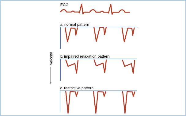
d. Assessment of diastolic LV function can be made by examining with PWD the transmitral inflow velocity profile during diastole. The normal pattern has an E wave corresponding to early passive filling of the LV, followed by a period of diastasis, and finally an A wave corresponding to atrial contraction in late diastole (Fig. 5.4A). Milder forms of diastolic dysfunction result in the impaired relaxation pattern with decreased peak E-to-A velocity ratio and prolonged E-wave deceleration time (Fig. 5.4B). Advanced diastolic dysfunction causes the restrictive pattern with increased peak E-to-A velocity ratio and decreased E-wave deceleration time (Fig. 5.4C). As diastolic dysfunction progresses from mild to severe over a number of years, the transmitral flow pattern may pass through a period in which it appears normal, a condition termed pseudonormal pattern. Normal may be distinguished from pseudonormal by examination of the pulmonary venous inflow velocity profile, which normally has positive inflow waves during systole (S wave) and diastole (D wave) and a small, negative wave corresponding to atrial contraction (A wave) (Fig. 5.5A). The pseudonormal pattern has prolongation of the A wave and attenuation of the S wave compared to the normal pattern (Fig. 5.5B). Age and preload also affect the transmitral and pulmonary venous inflow velocity patterns.
Figure 5.4 Transmitral inflow velocity profiles measured with PWD by placing the sample volume between the open tips of the mitral leaflets. A: Normal pattern. The pseudonormal pattern has a similar appearance. B: Impaired relaxation pattern indicative of mild diastolic dysfunction. The peak E-wave velocity is less than the A wave (E-to-A reversal) and the deceleration time of the E wave is prolonged. C: Restrictive pattern indicative of advanced diastolic dysfunction. The peak E-wave velocity is increased and the E-wave deceleration time is decreased. A, atrial filling wave; E, early filling wave.
Related posts:
 Devices for Cardiac Support and Replacement
 Alternative Approaches to Cardiac Surgery with and without Cardiopulmonary Bypass
 The Cardiac Surgical Patient
 Devices for Cardiac Support and Replacement
 Anesthetic Management for Patients with Congenital Heart Disease: The Adult Population
 Cardiovascular Drugs
Stay updated, free articles. Join our Telegram channel

Full access? Get Clinical Tree


