Chapter 1 The supply of anaesthetic and other medical gasses
Properties of medical gasses
The properties of some of the common medical gasses are summarized in Table 1.1. The newer gasses and their potential therapeutic indications are briefly discussed below.
Table 1.1 Physical properties of common pressurized gasses
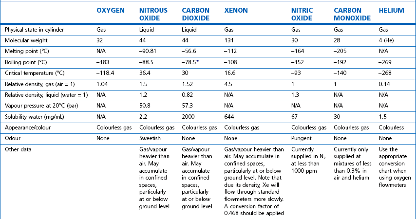
N/A, not applicable. * Sublimation.
Note: all values STP. Mixed gasses, e.g. Heliox, will have different physical properties. For exact values, please contact the manufacturer.
Details of carbogen (5% CO2 + 95% O2), lung function gasses, medical gasses for laser surgery and other agents not listed here are available from the manufacturers. Extensive information on the properties of all gasses and data sheets containing up-to-date product information can be obtained from the BOC Medical Gasses website www.bocmedical.com.
Heliox
• It has a lower density than air (0.42 kg/m3 vs 1.22 kg/m3 at 15°C and 1 atm) and hence a lower Reynolds number in any given situation, resulting in a higher likelihood of laminar gas flow characteristics.
• It has a higher thermal conductivity than air, which is of significance when its gas flow measurement is based on this principle (see Chapter 2, Hot wire anemometry).
Medical gas cylinders
Modern cylinders are manufactured using lightweight strong chrome-molybdenum steels which, as well as conforming to stringent material standards, can be filled to pressures of up to 300 bar g (where (g) denotes gauge pressure; see Chapter 2). Cylinders were previously made of the much heavier low-carbon steels: few of these are in circulation any longer in the UK.
Cylinder sizes
Technically, cylinders are defined by their water capacity and range between 1.2 L and 47.2 L, and are identified by a size code ranging from C to J (Fig. 1.1). This notation incorporates a pressure aspect to give an indication of available gas volume. Tables 1.2–1.7 give details for oxygen, nitrous oxide, Entonox, carbon dioxide, Heliox21, xenon, nitric oxide and carbon monoxide cylinders.
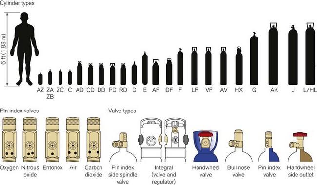
Figure 1.1 Cylinder types and sizes, valves types and pin index valves.
(from BOC Medical, with permission).
Table 1.4 Relative sizes and specifications of commonly used Entonox cylinders

Entonox, a mixture of 50% oxygen and 50% nitrous oxide, exists as a gas. The pseudo critical temperature of Entonox in pipelines at 4.1 bar is below −30°C. Nitrous oxide in an Entonox cylinder, however, begins to separate out from Entonox if the temperature falls below −6°C. A homogenous mixture is again obtained when the temperature is raised above 10°C and the cylinder is agitated.
Table 1.6 Relative sizes and specifications of commonly used Heliox21 cylinders
| CYLINDER SIZE | HL | HX |
|---|---|---|
| Contents (L) | 8200 | 1780 |
| Nominal cylinder pressure at 15°C (bar) | 200 | 200 |
| Valve type | Side outlet | Integral |
| Dimensions (mm) | 1540 × 230 | 940 × 140 |
| Empty weight (kg) | 50 | 15.5 |
Cylinder filling and maintenance
Most gasses such as oxygen, medical air, helium and Heliox21 are stored in cylinders in a compressed gaseous state and are normally filled by pressure. Nitrous oxide and carbon dioxide, however, are liquefied gasses under pressure. The liquid is in equilibrium with the gas, the pressure being dependent on the temperature. These gasses are charged by weight and not by pressure. The maximum weight of gas filled into the cylinder divided by the weight of water that would completely fill the cylinder is called the maximum filling ratio and is governed by legislation. This ‘fill ratio’, termed ‘fill density’ elsewhere, is critical. In the UK this value is 0.75 at 15.5°C for nitrous oxide and carbon dioxide. Note that due to the difference in the densities of liquefied gasses and water this ratio is not the same as the proportion of the volume of the cylinder filled by the liquid phase, which is nearer 90 to 95% for nitrous oxide. If there is insufficient gas space left in the cylinder after filling, a comparatively small increase in temperature will cause a significant increase in pressure and could, in extreme circumstances, cause the cylinder to rupture.
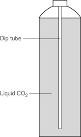
Some applications require carbon dioxide in liquid form. This is supplied using cylinders fitted with a ‘dip tube’ connected to the cylinder valve, which allows liquid from the bottom of the cylinder to be drawn up through the valve (Fig. 1.2). These cylinders, supplied in F size and known as LF, have a white stripe down the length of the cylinder body. For other CO2 applications where vapour is required, VF cylinders should be used. It is important to ensure that the correct cylinder is used to prevent damage to equipment.
Cylinder identification
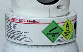
The correct method of identifying the contents of a cylinder is to read the collar identification label (rather than assuming that the colour of the cylinder or the type of valve fitted reliably indicates gas inside it). The label (Fig. 1.3) is a legal requirement and contains all the key information for the user:
• product name, chemical symbol and pharmaceutical form of the product
• directions for use and information for storage and handling.
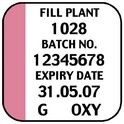
The cylinder label also has a unique batch label (Fig. 1.4), which contains: the batch number; fill and expiry date; and the size and type of gas. The label is changed every time the cylinder is filled and serves two important functions: (a) it provides vital information for a batch recall should the cylinder be involved in an incident; and (b) it provides information for proper cylinder rotation.
Cylinder testing
All cylinders must undergo hydraulic testing and internal inspection at regular intervals, to ensure they remain safe to use. The test is carried out every 10 years for steel cylinders and every 5 years for composite cylinders. A colour-coded plastic ring between the valve and the cylinder neck indicates when the next test date is due. In general, cylinders have a long service life and tend to be withdrawn for reasons of technical obsolescence rather than deterioration per se.
Colour coding
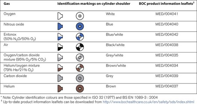
Medical cylinders in the UK conform to colour codes specified in ISO 32:1972 and EN 1089-3. The colour coding relates only to the shoulder of the cylinder. Figure 1.5 shows the colour codes for medical gas cylinders in the UK.
Cylinder valves
Medical cylinder valves can generally be categorized as follows:
• Non-integral valves (which require manual attachment of an external pressure regulator):
• Integral valves (which have a built in regulator and possibly flowmeter).
Pin index system
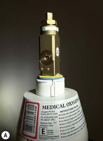
Small pin index valves (Fig. 1.6) are fitted to small cylinders (less than 5 litre capacity) which are commonly connected directly to medical equipment such as anaesthetic machines. Newer designs using a thumbwheel do away with the need for a spanner to operate the valve.
Side spindle pin index valves (Fig. 1.6) These are fitted to large cylinders of medical oxygen, medical air, Entonox used in pipeline manifolds and F size Entonox cylinders.
Both types of pin index valves conform to BS EN ISO 407:2004 and adopt an indexed outlet system which incorporates a gas-specific combination of holes positioned to correspond to pins located on the receiving equipment, making it impossible to connect the cylinder to an incorrect gas connection. Fig. 1.1 shows the different pin positions. The pin index system also prevents charging with the wrong gas, as the gas suppliers use the same non-interconnectable system for their filling connections.
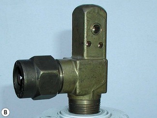
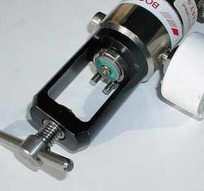
Pin index cylinders require a washer (seal) between the face of the cylinder valve outlet and the equipment to which it is fitted. This bonded non-combustible seal, known as a ‘Bodok’ washer (Figs 1.7 and 1.8), must be kept clean and should never become contaminated with oil or grease. If a gas tight seal cannot be achieved by moderate tightening of the screw clamp, it is recommended that the seal be renewed. Excessive force should never be used.
Bull nose outlet valve
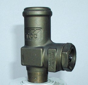
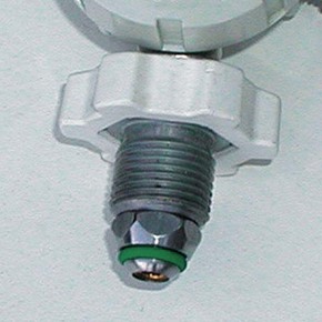
This type of valve (Fig. 1.9) is fitted to F and G size cylinders including medical oxygen, medical air, helium, and mixed gasses such as carbogen and Heliox. The valve is spindle key operated and has a 5/8-inch female outlet thread into which a regulator is fitted. The spindle mechanism is assembled in two parts. This permits a gas tight seal to be achieved without the use of excessive force and increases its operational life.
All bull nose valves are fitted with an RP (residual pressure) device, to ensure that a positive pressure of approximately 3 bar is retained in the cylinder (Fig. 1.10). This prevents the ingress of moisture should the valve be left open when the cylinder is empty. When connecting regulator equipment to the valve, the user should always adopt the proper connecting procedure:
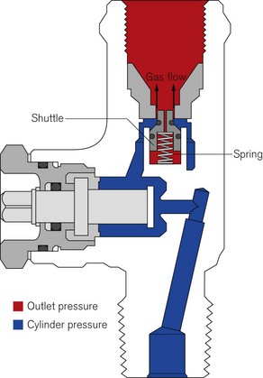
Figure 1.10 Schematic showing ‘residual pressure’ device of a bull nose cylinder valve.
Redrawn using material kindly provided by Müller Gas Equipment A/S, Denmark.
• Ensure the ‘O’ ring (Fig. 1.11) fitted to the regulator is in good condition and hand tighten the regulator only.
• Once fitted, open the spindle valve slowly (to prevent a gas surge) at least one full turn and note the position of the regulator gauge needle.
• A simple test for leaks can be carried out by closing the cylinder spindle valve and noting any drop in pressure shown on the gauge. If a leak does exist, spraying the joints with a leak detection spray will identify it. If a leak is evident at the valve outlet, replace the ‘O’ ring and repeat the procedure. If the leak persists, fit a replacement regulator. (Note: It is vitally important that any leak detection spray has been approved by the cylinder supplier as being compatible with their equipment and the gas.)
• When changing an empty cylinder, close the cylinder valve and vent the regulator completely before attempting to disconnect it.
Handwheel valves
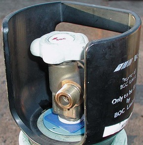
Large nitrous oxide cylinders for use on cylinder manifolds and carbon dioxide cylinders of size F and G are fitted with handwheel valves which are surrounded by a protective guard (Fig. 1.12), and have a gas specific, male thread, side outlet.
Integral valves
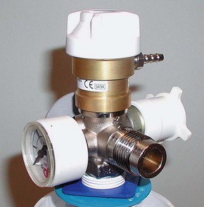
The introduction of integral valves (Fig. 1.13), which have their own built-in regulator, has revolutionized the industry by greatly improving safety and eliminating the need for regulator maintenance by hospitals. They have a number of advantages:
• The regulator assembly is manufactured in a clean environment and is much less prone to particulate contamination.
• The built-in regulator eliminates the risk of incorrect regulator attachment which could result in damage to lower-pressure rated equipment.
• The valves are surrounded by guards which reduce the risk of damage and ease manual handling of the cylinder.
• They are considerably easier to use and have live pressure gauges built in for checking cylinder contents.
• The valves possess two outlets – a variable flow outlet (via a fir tree connector) and a fixed pressure outlet to connect equipment requiring a static driving pressure.
A commonly encountered version of the integral valve has a combination of a clickstop flowmeter giving 0–15 l min−1 in stepped increments and a female BS Schraeder connection at 4 bar g to provide high pressure gas. This type of valve is currently fitted to cylinders of up to 10 l water capacity. Care must be taken to ensure that the flowmeter selector dial is not ‘parked’ between click stops as this will result in a cessation of gas flow.
Storage of medical gas cylinders
• be under cover (preferably inside) and not subjected to extremes of heat
• be kept dry, clean and well ventilated
• have good access for deliveries and a reasonably level floor surface
• allow segregation of ‘full’ and ‘empty’ cylinders
Stay updated, free articles. Join our Telegram channel

Full access? Get Clinical Tree


