The Anesthesia Workstation and Delivery Systems for Inhaled Anesthetics
Kevin T. Riutort
James B. Eisenkraft
Key Points
Related Matter
Bourdon Tube
Circle System
Liquid Oxygen Storage Tank
E-Cylinder
Oxygen Proportioning Systems
Oxygen Flush Valve
Vaporizer Interlocking Mechanism
Desflurane
CO2 Absorber
Rebreathing CO2
Ventilator Bellows
Ascending Bellows Ventilator
Wire Anenometers
Scavenger System
Introduction
The anesthesia machine is, conceptually, a pump for delivering medical gases and inhalation agents to the patient’s lungs. The function of the anesthesia machine is to (1) receive gases from the central supply and cylinders, (2) meter them and add anesthetic vapors, and finally, (3) deliver them to the patient breathing circuit.1 This machine has evolved over the past 160 years from a rather simple ether inhaler to a complex device of valves, pistons, vaporizers, monitors, and electronic circuitry.
The “pump” in the modern anesthesia machine is either a mechanical ventilator or the lungs of the spontaneously breathing patient, or perhaps, a combination of the two. The anesthesia
pump has a supply system: medical gases from either a pipeline supply or a gas cylinder, alongside vaporizers delivering potent inhaled anesthetic agents that are mixed with the medical gases. The anesthesia pump also has an exhaust system, the waste gas scavenging system, which removes excess gases from the patient’s breathing circuit. The breathing circuit is a series of hoses, valves, filters, switches, and regulators that interconnect the supply system, the patient, and the exhaust system.
pump has a supply system: medical gases from either a pipeline supply or a gas cylinder, alongside vaporizers delivering potent inhaled anesthetic agents that are mixed with the medical gases. The anesthesia pump also has an exhaust system, the waste gas scavenging system, which removes excess gases from the patient’s breathing circuit. The breathing circuit is a series of hoses, valves, filters, switches, and regulators that interconnect the supply system, the patient, and the exhaust system.
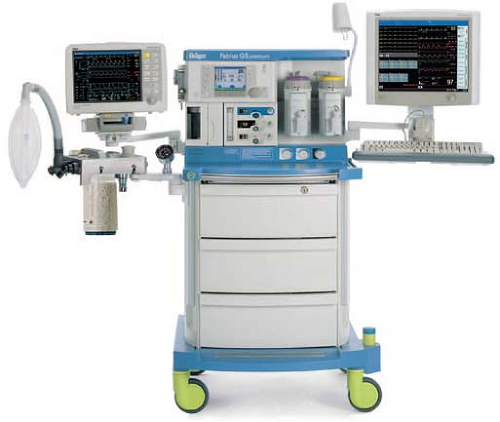 Figure 24.1. Dräger Medical Fabius GS anesthesia workstation. (Courtesy Dräger Medical AG.) |
Modern anesthesia machines (Figs. 24-1 and 24-2) are now more properly referred to as anesthesia workstations. The anesthesia workstation, as defined by the ASTM International (ASTM, originally known as the American Society for Testing and Materials), is a system for administering anesthetics to patients consisting of the anesthesia gas supply device, the anesthesia ventilator, monitoring devices, and protection devices.2 The protection device is designed to prevent the patient from hazardous output due to incorrect delivery of energy or substances; for example, the adjustable pressure-limiting (APL) valve prevents barotrauma.
In this chapter, the anesthesia workstation is examined piece by piece. The normal operation, function, and integration of major anesthesia workstation subsystems are described. More importantly, the potential problems and hazards associated with the various components of the anesthesia delivery system, and the appropriate preoperative checks that may help to detect and prevent such problems, are illustrated.
Anesthesia Workstation Standards and Pre-Use Procedures
A few years ago, a fundamental knowledge of the basic anesthesia machine pneumatics would have sufficed for most anesthesia providers. Today, a detailed understanding of pneumatics, electronics, and even computer science is necessary to fully understand the capabilities and complexities of the anesthesia workstation. Along with the changes in the composition of the anesthesia workstation to include more complex ventilation systems and integrated monitoring, recently there has also been increasing divergence between anesthesia workstation designs from different manufacturers. In 1993, a joint effort between the American Society of Anesthesiologists (ASA) and the U.S. Food and Drug Administration (FDA) produced the 1993 FDA Anesthesia Apparatus Pre-Use Checkout Recommendations (Appendix A). This pre-use checklist was versatile and could be applied to most commonly available anesthesia machines equally well and did not require users to vary the pre-use procedure significantly from machine to machine.
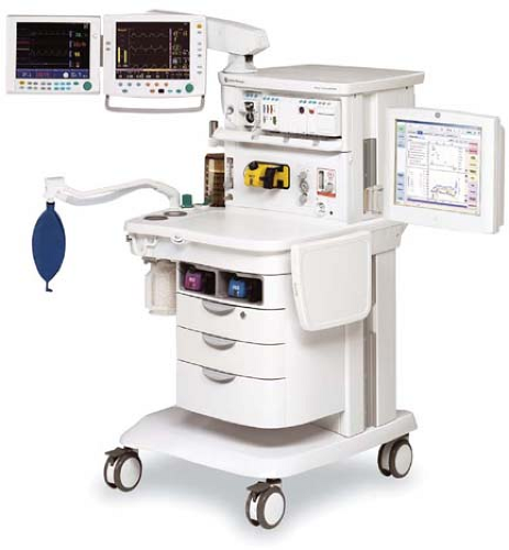 Figure 24.2. GE Healthcare Aisys Anesthesia Carestation. This workstation has electronic control of gas flows using a gas mixer and an electronically controlled Aladin vaporizing system for potent inhaled volatile anesthetics. (Courtesy GE Healthcare.) |
Today, because of variations in fundamental anesthesia workstation design, the 1993 FDA pre-use checklist is no longer applicable to many contemporary workstations. Anesthesia providers must be aware of this limitation, and the original equipment manufacturer’s recommended pre-use checklist should be followed. Some of the newer workstations have computer-assisted self-tests that automatically perform a part of the pre-use machine checkout procedure. The availability of such automated checkout features further adds to the complexity of constructing a uniform pre-use checklist such as the one utilized in the recent past. Ultimately, the responsibility of performing an adequate pre-use checkout of the anesthesia workstation falls to the individual operator: regardless of the level of his/her training and the quality of technical support. The anesthesia care provider has the ultimate responsibility for proper function of all anesthesia delivery equipment that he or she uses. The anesthesia provider of record must be aware of which anesthesia workstation components are checked out by the automated self-tests and which ones are not. Because of the number of workstations currently available and the variability among their self-testing procedures, the following discussion will be limited to general topics related to these systems.
Standards for Anesthesia Machines and Workstations
The American National Standards Institute (ANSI) and the American Society for Testing and Materials (ASTM) define standards for anesthesia machines and workstations, and provide guidelines to manufacturers regarding their minimum performance, design characteristics, and safety requirements. Newly manufactured workstations must have monitors that measure the following parameters: continuous breathing system pressure, exhaled tidal volume, ventilatory CO2 concentration, anesthetic vapor concentration, inspired oxygen concentration, oxygen supply pressure, arterial hemoglobin oxygen saturation, arterial blood pressure, and continuous electrocardiogram. The anesthesia workstation must have a prioritized alarm system that groups the alarms into three categories: high, medium, and low priority. These monitors and alarms may be enabled automatically and made to function by turning on the anesthesia workstation, or the monitors and alarms can be enabled manually and made functional by following a pre-use checklist.2,3
Perhaps just as important as the specifications for new anesthesia machines and workstations that are introduced into clinical care are the characteristics that render older machines obsolete. This is not an inconsequential issue, since the financial investment for replacing older machines is significant. The ASA document, “Guidelines for Determining Anesthesia Machine Obsolescence,” addresses some of the absolute as well as relative criteria that can help institutions make a decision on when even otherwise functioning equipment should be replaced.4
Failure of Anesthesia Equipment
An 11-year study of 1,000 anesthesia incidents in the United Kingdom revealed that the most common failure was due to an equipment leak (61/1,000).5 The authors stated the most likely underlying cause of system leaks was due to “design weakness”; for example, push-on tapers in breathing circuits that can easily become disconnected. Poor equipment maintenance and setup were the second most common underlying causes of equipment failure. Equipment failure due to entrapped cables may result in the inability to ventilate (thus warranting careful attention to organization and tidiness of the anesthesia workstation environment by the anesthesia provider).6,7,8 The authors found that the pulse oximeter alarm was the most common, principal monitor alerting the anesthesiologist to an equipment problem.
In a review of the ASA “Closed Claims” database, Caplan et al. found that although claims related to the medical gas-delivery system were rare, when they occurred, they were usually severe, 76% resulting in death or permanent brain injury. The most common malfunction in Caplan et al’s review was the breathing circuit (39%), followed by vaporizers (21%), ventilators (17%), gas tanks or gas lines (11%), and the anesthesia machine itself (7%). Use error was judged to be the cause in 75% of the 72 gas delivery equipment claims reviewed, while pure failure of equipment was considered the cause in the remainder.9
Safety Features of Newer Anesthesia Workstations
Older conventional anesthesia machines have design limitations that limit their safety. For example, some machines may lack features to prevent barotrauma during oxygen flush, lack automated pre-use checkout, have multiple external connections, and have gas-driven ventilator bellows that do not fully empty and which may allow “breath stacking” as well as inaccurate tidal volume delivery.10
Modern workstations have designs that incorporate additional safety features such as fresh gas decoupling to prevent barotrauma during oxygen flush, have integrated, software-driven self-checkout routines, have limited external connections, and have electronic, piston-driven ventilators that deliver accurate tidal volumes.10 Table 24-1 summarizes relevant safety features of newer anesthesia workstations.
Checkout of the Anesthesia Workstation
A complete anesthesia apparatus checkout procedure must be performed each day prior to the first use of the anesthesia workstation. An abbreviated checkout procedure should be performed before each subsequent case. The 1993 FDA Anesthesia Apparatus Checkout Recommendations (reproduced in Appendix A) remain applicable to the majority of older anesthesia machines in use worldwide.11,12,13,14,15
In 2008 the ASA published recommendations for pre-anesthesia checkout machines, taking into consideration newer workstations that perform automated checkout.16 Since the design of newer workstations varies considerably, no single pre-use procedure is applicable. These guidelines present a template for individual departments and practitioners to design pre-anesthesia checkout procedures specific to their needs and equipment (Appendix B). Sample checkout procedures are published on the ASA website (http://www.asahq.org), and they encompass adult as well as pediatric equipment from major equipment manufacturers in the United States. The reader is strongly encouraged to review the checkout procedures reproduced in Appendices A and B and to understand the rationale for and importance of each step.
The next three most important preoperative checks are (1) oxygen analyzer calibration, (2) the low-pressure circuit leak test, and (3) the circle system test. These are discussed in the following sections. Additional details regarding these systems are presented briefly in subsequent sections describing the anatomy of the anesthesia workstation; for a more comprehensive review, the reader is encouraged to consult the operator’s manual of their own equipment manufacturer. For a simplified diagram of a two-gas anesthesia machine and the components described in the following discussion, please refer to Figure 24-4. A comprehensive discussion of Figure 24-4 can also be found in the Anesthesia Workstation Pneumatics section.
Oxygen Analyzer Calibration
The oxygen analyzer is one of the most important monitors on the anesthesia workstation. It is the only machine safety device
that evaluates the integrity of the low-pressure circuit in an ongoing fashion. Other machine safety devices, such as the oxygen failure cutoff (“fail-safe”) valve, the oxygen supply failure alarm, and the proportioning system, are all upstream from the flow control valves. The only machine monitor that detects problems downstream from the flow control valves is the oxygen analyzer. Calibration of this monitor is described in Appendix A (Anesthesia Apparatus Checkout Recommendations, 1993, Step 9). The actual procedure for calibrating the oxygen analyzer has remained reasonably similar over the recent generations of the anesthesia workstations (Guideline for Designing Pre-Anesthesia Checkout Procedures, 2008, Item 10 in Appendix B). Generally, the oxygen concentration-sensing element (usually a fuel cell on traditional machines) must be exposed to room air (at sea level) for calibration to 21%. This may require manually setting a dial on older machines, but on newer ones, it usually only involves temporary removal of the sensor, selecting and then confirming that the oxygen calibration is to be performed from a set of menus on the workstation’s display screen, and finally reinstalling the sensor. The function of the low oxygen concentration alarm should be verified by setting the alarm to trigger above the current oxygen reading. Newer workstations have automatic oxygen sensor calibration.
that evaluates the integrity of the low-pressure circuit in an ongoing fashion. Other machine safety devices, such as the oxygen failure cutoff (“fail-safe”) valve, the oxygen supply failure alarm, and the proportioning system, are all upstream from the flow control valves. The only machine monitor that detects problems downstream from the flow control valves is the oxygen analyzer. Calibration of this monitor is described in Appendix A (Anesthesia Apparatus Checkout Recommendations, 1993, Step 9). The actual procedure for calibrating the oxygen analyzer has remained reasonably similar over the recent generations of the anesthesia workstations (Guideline for Designing Pre-Anesthesia Checkout Procedures, 2008, Item 10 in Appendix B). Generally, the oxygen concentration-sensing element (usually a fuel cell on traditional machines) must be exposed to room air (at sea level) for calibration to 21%. This may require manually setting a dial on older machines, but on newer ones, it usually only involves temporary removal of the sensor, selecting and then confirming that the oxygen calibration is to be performed from a set of menus on the workstation’s display screen, and finally reinstalling the sensor. The function of the low oxygen concentration alarm should be verified by setting the alarm to trigger above the current oxygen reading. Newer workstations have automatic oxygen sensor calibration.
Table 24-1. Comparison of Anesthesia Workstation Functions | |
|---|---|
|
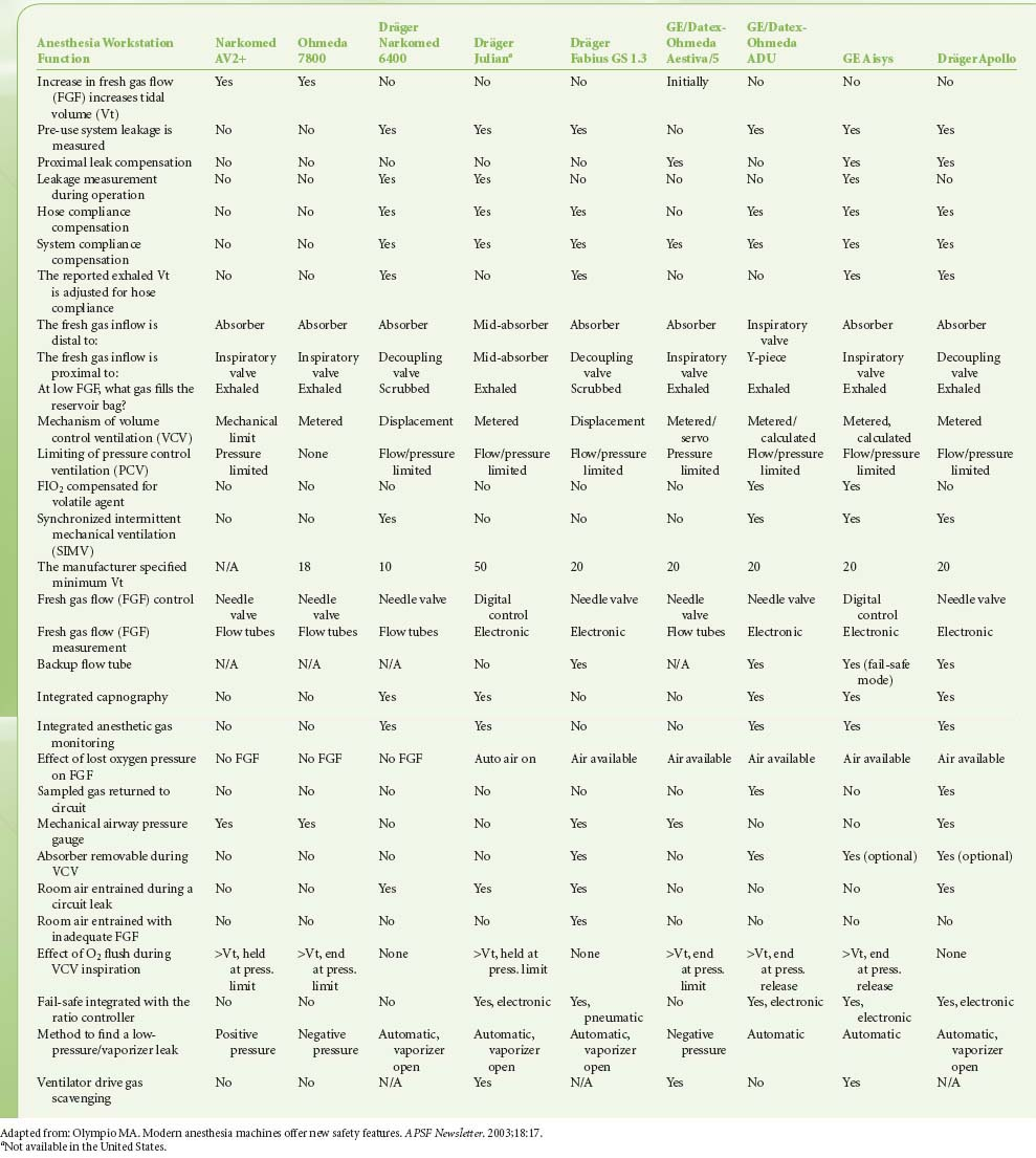
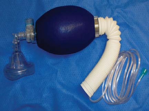 Figure 24.3. Self-inflating resuscitation bag (SIRB). Many of the adverse outcomes associated with anesthesia equipment mishaps could have been averted if a functional SIRB had been used sooner. |
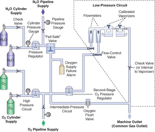 Figure 24.4. Diagram of a generic two-gas anesthesia machine. (Modified with permission from: Check-Out, A Guide for Preoperative Inspection of an Anesthesia Machine. Park Ridge, IL: American Society of Anesthesiologists; 1987.) |
Low-Pressure Circuit Leak Test
lead to delivery of sub-anesthetic doses of inhaled agents, causing patient awareness during general anesthesia.18,21
Several different methods have been used to check the low-pressure circuit for leaks. They include the oxygen flush test, the common gas outlet occlusion test, the traditional positive-pressure leak test, the North American Dräger positive-pressure leak test, the Ohmeda 8000 internal positive-pressure leak test, the Ohmeda negative-pressure leak test, the 1993 FDA universal negative-pressure leak test, and others. One reason for the large number of methods is that the internal design of various machines differs considerably. The most notable example is that many GE Healthcare/Datex-Ohmeda (hereafter referred to as Datex-Ohmeda) machines/workstations have a check valve near the common gas outlet, whereas Dräger Medical workstations do not. The presence or absence of the outlet check valve profoundly influences which pre-use check is indicated.
Generally speaking, the low-pressure circuit of anesthesia workstations without an outlet check valve can be tested using a positive-pressure leak test, and machines with outlet check valves must be tested using a negative-pressure leak test. When performing a positive-pressure leak test, the operator generates positive pressure in the low-pressure circuit using flow from the anesthesia machine or from a positive-pressure squeeze bulb to detect a leak. When performing a negative-pressure leak test, the operator creates negative pressure in the low-pressure circuit using a suction bulb to detect leaks. Two different low-pressure circuit leak tests are described below.
Oxygen Flush Positive-Pressure Leak Test
Historically, older anesthesia machines did not have check valves in the low-pressure circuit. Therefore, it was common practice to pressurize the breathing circuit and the low-pressure circuit with the oxygen flush valve to test for internal anesthesia machine leaks by observing the breathing system pressure gauge. Because many modern Datex-Ohmeda machines now have check valves in the low-pressure circuit, application of a positive-pressure leak test to these machines can be misleading or even dangerous (Fig. 24-5). Inappropriate use of the oxygen flush valve or the presence of a leaking flush valve may lead to inadequate evaluation of the low-pressure circuit for leaks. In turn, this can lead the workstation user into a false sense of security despite the presence of large leaks.22,23,24,27,28 Positive pressure from the breathing circuit results in closure of the outlet check valve, and the value on the breathing system pressure gauge will fail to decrease. The system appears to be gas tight, but in actuality, only the circuitry downstream from the outlet check valve is leak-free.29 Thus, a vulnerable area exists from the check valve back to the flow control valves because this area is not tested by a positive-pressure leak test.
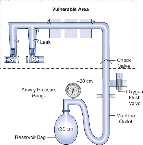 Figure 24.5. Inappropriate use of the oxygen flush valve to check the low-pressure circuit of an Ohmeda machine equipped with a check valve. The area within the rectangle is not checked by the inappropriate use of the oxygen flush valve. The components located within this area are precisely the ones most subject to breakage and leaks. Positive pressure within the patient circuit closes the check valve, and the value on the airway pressure gauge does not decrease despite leaks in the low-pressure circuit. |
Verifying the Integrity of the Gas Supply Lines between the Flowmeters and the Common Gas Outlet
The 1993 FDA low-pressure system leak check is based on the Datex-Ohmeda negative-pressure leak test (Fig. 24-6). It is performed using a negative-pressure leak testing device, which is a simple suction 15 cc volume bulb that when evacuated generates a negative pressure of 65 mm Hg. The machine main ON/OFF switch, the flow control valves, and the vaporizers are all turned off. The suction bulb is connected to the common gas outlet and
squeezed repeatedly until it is fully collapsed. This action creates a vacuum in the low-pressure system circuitry. The machine is considered leak-free if the suction bulb remains collapsed for at least 10 seconds. A leak is present if the bulb reinflates during this period. The test is repeated with each vaporizer individually turned to the on position because internal vaporizer leaks can be detected only when the vaporizer is turned on and becomes part of the low-pressure system. If the bulb reinflates in less than 10 seconds, a leak is present somewhere in the low-pressure circuit.
squeezed repeatedly until it is fully collapsed. This action creates a vacuum in the low-pressure system circuitry. The machine is considered leak-free if the suction bulb remains collapsed for at least 10 seconds. A leak is present if the bulb reinflates during this period. The test is repeated with each vaporizer individually turned to the on position because internal vaporizer leaks can be detected only when the vaporizer is turned on and becomes part of the low-pressure system. If the bulb reinflates in less than 10 seconds, a leak is present somewhere in the low-pressure circuit.
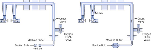 Figure 24.6. FDA negative-pressure leak test. (Left) A negative-pressure leak testing device is attached directly to the machine common gas outlet. Squeezing the bulb creates a vacuum in the low-pressure circuit and opens the check valve. (Right) When a leak is present in the low-pressure circuit, room air is entrained through the leak and the suction bulb inflates. (Reprinted with permission from: Andrews JJ. Understanding anesthesia machines. In: 1988 Review Course Lectures, p 78. Cleveland: International Anesthesia Research Society, 1988.) |
Evaluation of the Circle System
In the 1993 FDA Anesthesia Apparatus Checkout Recommendations, a leak test is performed by closing the APL (or pop-off) valve, occluding the Y-piece, and pressurizing the circuit to 30 cm water pressure using the oxygen flush valve. The value on the pressure gauge will not decrease if the circle system is leak-free, but this does not assure unidirectional valve integrity or function. The value on the pressure gauge will read 30 cm H2O even if the unidirectional valves are stuck shut or are incompetent. In addition, a flow test checks the integrity of the unidirectional valves, and it detects obstruction in the circle system. It can be performed by removing the Y-piece from the circle system and breathing through the two corrugated hoses individually. The unidirectional valve leaflets should be present and should move appropriately. The operator should be able to inhale but not be able to exhale through the inspiratory limb. The operator should be able to exhale but not inhale through the expiratory limb. The flow test can also be performed by using the ventilator and a reservoir bag connected to the “Y” piece as described in the 1993 FDA
Anesthesia Apparatus Checkout Recommendations (Appendix A, Steps 11–12).13
Anesthesia Apparatus Checkout Recommendations (Appendix A, Steps 11–12).13
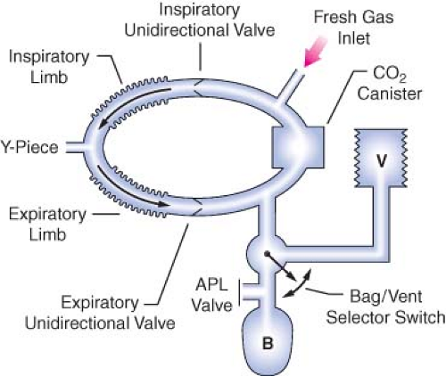 Figure 24.7. Components of the circle breathing system. B, reservoir bag; V, ventilator; APL, adjustable pressure-limiting (pop-off) valve. (Reproduced with permission from: Brockwell RC. Inhaled anesthetic delivery systems. In: Miller RD, ed. Anesthesia. 6th ed. Philadelphia, PA: Churchill Livingstone; 2004:295.) |
Workstation Self-Tests
Many new anesthesia workstations now incorporate technology that allows the machine to either automatically or manually guide the user through a series of self-tests to check for functionality of electronic, mechanical, and pneumatic components. Tested components commonly include the gas supply system, flow control valves, the circle system, ventilator, and integrated vaporizers. The comprehensiveness of these self-diagnostic tests varies from one model and manufacturer to another. If these tests are to be employed, users must be certain to read and strictly follow all manufacturer recommendations. Although a thorough understanding of what the particular workstation’s self-tests include is very helpful, this information is often difficult to obtain and may vary greatly between devices.
Anesthesia Workstation Pneumatics
The Anatomy of an Anesthesia Workstation
A simplified diagram of a generic two-gas anesthesia machine is shown in Figure 24-4. The pressures within the anesthesia workstation can be divided into three circuits: a high-pressure, an intermediate-pressure, and a low-pressure circuit. The high-pressure circuit is confined to the cylinders and the cylinder primary pressure regulators. For oxygen, the pressure range of the high-pressure circuit extends from a high of 2,200 pounds per square inch gauge (psig) to 45 psig, which is the regulated cylinder pressure. For nitrous oxide in the high-pressure circuit, pressures range from a high of 750 psig in the cylinder to a low of 45 psig. The intermediate-pressure circuit begins at the regulated cylinder supply sources at a pressure of 45 psig, includes the pipeline sources at 50 to 55 psig and extends to the flow control valves. Depending on the manufacturer and specific machine design, second-stage pressure regulators may be used to decrease the pipeline supply pressures to the flow control valves to even lower pressures such as 14 psig or 26 psig within the intermediate-pressure circuit.32,33 Finally, the low-pressure circuit extends from the flow control valves to the common gas outlet. Therefore, the low-pressure circuit includes the flow tubes, vaporizer manifold, vaporizers, and the one-way outlet check valve on most GE Healthcare/Datex-Ohmeda machines.33
A safety device traditionally referred to as the fail-safe valve (and currently more appropriately termed the “oxygen failure cutoff valve”) is located downstream from the nitrous oxide supply source. It serves as an interface between the oxygen and nitrous oxide supply sources. This valve shuts off, or proportionally decreases, the supply of nitrous oxide (and other gases) if the oxygen supply pressure decreases. To meet ASTM standards, contemporary machines have an alarm device to monitor the oxygen supply pressure. A high-priority alarm is actuated when a decreasing oxygen supply pressure reaches a predetermined threshold, such as 30 psig.32,33,34
Many GE Healthcare/Datex-Ohmeda machines have a second-stage pressure regulator for oxygen that is located downstream from the oxygen supply source in the intermediate-pressure circuit. It is adjusted to a precise pressure level, such as 14 psig.32 This regulator supplies a constant pressure to the oxygen flow-control valve regardless of fluctuating oxygen pipeline pressures. The flow from the oxygen flow-control valve will be constant provided that its oxygen supply pressure is >14 psig.
The flow control valves represent an important anatomic landmark within the anesthesia workstation because they separate the intermediate-pressure circuit from the low-pressure circuit. The low-pressure circuit is that part of the machine that lies downstream from the flow control valves. The operator regulates flow entering the low-pressure circuit by adjusting the flow control valves. The oxygen and nitrous oxide flow-control valves are linked mechanically or pneumatically by a proportioning system to help prevent unintended delivery of a hypoxic mixture. After leaving the flow tubes, the mixture of gases travels through a common manifold and may be directed to a concentration-calibrated vaporizer. Precise amounts of potent inhaled volatile anesthetic can be added, depending on vaporizer concentration control dial setting. The total fresh gas flow (FGF) plus the anesthetic vapor then flow toward the common gas outlet.32,33
Many Datex-Ohmeda anesthesia machines have a one-way check valve located between the vaporizers and the common gas outlet in the mixed-gas line. Its purpose is to prevent back flow into the vaporizer during positive-pressure ventilation, therefore minimizing the effects of downstream intermittent pressure fluctuations on inhaled anesthetic concentration (see Vaporizers: Intermittent Back Pressure section). The presence or absence of this check valve profoundly influences which preoperative leak test is indicated (see Checking Your Anesthesia Workstation). The oxygen flush connection joins the mixed-gas line between the one-way check valve (when present) and the machine common gas outlet. Thus, when the oxygen flush valve is activated the pipeline oxygen flows directly to the common gas outlet at a rate of 35 to 75 L/min and potentially at a pressure of 55 psig.
Pipeline Supply Source
Most hospitals today have a central piping system to deliver medical gases including oxygen, nitrous oxide, air, and carbon dioxide to outlets in the operating room. The central piping system must supply the correct gases at the appropriate pressure for the anesthesia workstation to function properly. Unfortunately, this does not always occur. Even as recently as 2002, a large medical center with a huge cryogenic bulk oxygen storage system was not immune to component failures that contributed to a critical oxygen pipeline
supply failure.35 In this case, a faulty joint ruptured at the bottom of the primary cryogenic oxygen storage tank, releasing 8,000 gallons of liquid oxygen to flood the streets in the surrounding area and compromised oxygen delivery to the medical center.
supply failure.35 In this case, a faulty joint ruptured at the bottom of the primary cryogenic oxygen storage tank, releasing 8,000 gallons of liquid oxygen to flood the streets in the surrounding area and compromised oxygen delivery to the medical center.
In a 1976 survey of approximately 200 hospitals, 31% reported difficulties with pipeline systems.36 The most common problem was inadequate oxygen pressure, followed by excessive pipeline pressures. The most devastating reported hazard, however, was accidental crossing of oxygen and nitrous oxide pipelines, which has led to many deaths. This problem caused 23 deaths in a newly constructed wing of a general hospital in Sudbury, Ontario, during a 5-month period.37 In 2002, two hypoxic deaths were reported in New Haven, Connecticut. These resulted from a medical gas system failure in which an altered oxygen flowmeter was connected to a wall supply source for nitrous oxide.38
The wall outlet connections for pipeline gases are gas-specific. If they are “quick connect” fittings then they are gas-specific within the same manufacturer. For example, a wall oxygen outlet made by Ohmeda will not accept an oxygen connector made by Chemetron, even though the gas is the same. This can create problems if outlets and connectors by more than one manufacturer exist in the same facility.41 Many institutions seeking to create uniformity are now using nationally standardized Diameter Index Safety System (DISS) threaded connections. The DISS provides threaded, noninterchangeable connections for medical gas lines, which minimizes the risk of misconnection. Regardless of which type of gas-specific connector (DISS or “quick connect”) exists at the wall end of the hose conducting gas to the anesthesia machine, the gas enters the anesthesia machine through DISS inlet connections (see Fig. 24-4; arrows). A pressure gauge measures the pipeline gas pressure when the machine is connected to a pipeline supply. A check valve is located downstream from the inlet. It prevents reverse flow of gases from the machine to the pipeline or the atmosphere.
Cylinder Supply Source
Anesthesia workstations have E-cylinders for use when a pipeline supply source is not available or if the pipeline system fails. Anesthesia providers can easily become complacent and falsely assume that backup gas cylinders are, in fact, present on the anesthesia workstation, and further, if present, that they contain an adequate supply of compressed gas. The pre-use checklist should contain steps that confirm both.
Medical gases supplied in E-cylinders are attached to the anesthesia machine via the hanger yoke assembly. The hanger yoke assembly orients and supports the cylinder, provides a gas-tight seal, and ensures a unidirectional flow of gases into the machine.33 Each hanger yoke is equipped with the Pin Index Safety System (PISS). The PISS is a safeguard introduced to eliminate cylinder interchanging and the possibility of accidentally placing the incorrect gas on a yoke designed to accommodate another gas. Two metal pins on the yoke assembly are arranged so that that they project into corresponding holes in the cylinder valve. Each gas or combination of gases has a specific and unique pin arrangement.42,43 A failure of the pin index system, and medical staff to properly identify E-cylinder contents, was the cause of an intraoperative fire during laparoscopy.44 A mixture of oxygen and CO2 was utilized rather than 100% CO2.
Once the cylinders are turned on, compressed gases may pass from their respective high-pressure cylinder sources into the anesthesia machine (see Fig. 24-4). A check valve is located downstream from each cylinder if a double-yoke assembly is used. This check valve serves several functions. First, it minimizes gas transfer from a cylinder at high pressure to one with a lower pressure. Second, it allows an empty cylinder to be exchanged for a full one while gas flow continues from the other cylinder into the machine with minimal loss of gas or supply pressure. Third, it minimizes leakage from an open cylinder to the atmosphere if one cylinder is absent.32,33 A cylinder supply pressure gauge is located downstream from the check valves. The gauge will indicate the pressure in the cylinder having the higher pressure when two reserve cylinders of the same gas are opened at the same time.
Each cylinder supply source has a pressure-reducing valve known as the cylinder pressure regulator. It reduces the high and variable storage pressure present in a cylinder to a lower, more constant pressure suitable for use in the anesthesia machine. The oxygen cylinder pressure regulator reduces the oxygen cylinder pressure from a high of 2,200 psig to approximately 45 psig. The nitrous oxide cylinder pressure regulator receives pressure of up to 745 psig and reduces it to approximately 45 psig.32,33
The gas supply cylinder valves should be turned off when not in use, except during the preoperative machine pre-use checkout. If the cylinder supply valves are left open, the reserve cylinder supply can be silently depleted whenever the pressure inside the machine decreases to a value lower than the regulated cylinder pressure. For example, oxygen pressure within the machine can decrease below 45 psig with oxygen flushing or possibly even during the use of a pneumatically driven ventilator, particularly at high inspiratory flow rates. In addition, the pipeline supply pressures of all gases can fall to less than 45 psig if problems exist in the central piping system. If the cylinders are left open when this occurs, they will eventually become depleted and no reserve supply may be available if a complete central pipeline failure were to occur.29,32
The amount of time that an anesthesia machine can operate from the E-cylinder supply is important knowledge. This is particularly true now that anesthesia is being provided more frequently in office-based and in remote (outside the OR) hospital settings where pipeline oxygen may not be available. Oxygen can exist only in gaseous form at room temperature, and it obeys Boyle’s law which states that for a fixed mass of gas at constant temperature, the product of pressure times volume is constant.45 The volume of oxygen available from the cylinder is directly proportional to the cylinder pressure.
Therefore, V2, the volume of oxygen in a “full” E-cylinder at 1 atm is
The following equation has been proposed to help estimate the remaining time that oxygen can be delivered at a given flow rate46:
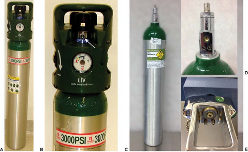 Figure 24.8. (A) 3,000 psig E-cylinder with Linde Integrated Valve LIV (B), Linde Gas North America LLC that permits adjustable flows of ¼ to 25 L/min from the low-pressure nozzle (B-arrow). There is also a high-pressure regulator that can supply oxygen at 50 psig via a DISS connector. Standard E-cylinder (C) showing pin-index safety system (D) and mating yoke (E). |
For example, an E-cylinder of oxygen with a pressure of 1,000 psig, used at an oxygen flow rate of 5 L/min would be depleted in
It should be noted that this calculation will provide only a gross estimate of remaining time and may not be exact. Furthermore, users should be cautioned that use of a pneumatically driven mechanical ventilator will dramatically increase oxygen utilization rates and decrease the remaining time until the cylinder is depleted. Uses of spontaneous or manual ventilation, with low FGF rates in a circle system with CO2 absorption, will significantly reduce oxygen consumption from an E-cylinder if this is the only source of oxygen available.7,8,35 Because electrically powered piston type anesthesia ventilators, such as found in the Dräger Fabius GS and Apollo workstations, do not impact oxygen usage rates they may be preferable to conventional gas-driven ventilators in practice settings where the supply of compressed gas cylinders may be limited.
A new regulator for E-cylinders of oxygen is available that permits controlled delivery of oxygen via a nozzle at flows of ≤25 L/min for patient transport (Fig. 24-8 A,B,C,D and E). The tank regulator also permits delivery of oxygen at 50 psig from a DISS connection (Fig. 26-9). If the oxygen hose from the anesthesia machine is connected to a central source (e.g., at the wall) via a DISS connector, and that central source becomes unavailable, then the machine hose can be easily connected to the tank’s DISS connector and provide a backup supply of oxygen (Fig. 24-9 B). A conventional E cylinder with pin index safety system is shown in Fig. 24-8C,D,E.
Nitrous Oxide
Nitrous oxide (N2O) can be supplied to the anesthesia machine from the pipeline system at a pressure of approximately 50 psig or from a backup E-cylinder in the N2O hanger yoke. N2O has a molecular weight of 44 atomic mass units (AMU) and a boiling point of −88°C at 760 mm Hg (14.7 psia) pressure.47 The critical temperature (CT) is the highest temperature at which a gas can exist in liquid form. The CT of N2O is 36.5°C (critical pressure: 1,054 psig), therefore N2O can exist as a liquid at room temperature (20°C). E-cylinders of N2O are factory-filled to 90% to 95% capacity with liquid N2O. Above the liquid in the tank is N2O vapor. Because the liquid agent is in equilibrium with its vapor or gas phase, the pressure exerted by the gaseous N2O is its saturated vapor pressure (SVP) at the ambient temperature. At 20°C, the SVP of N2O is 750 psig.
A full E-tank of N2O generates approximately 1,600 L of gas at 1 atm pressure at sea level (14.7 psia). As long as some liquid N2O is present in the tank and the ambient temperature remains at 20°C, the pressure in the N2O tank will remain at 750 psig, which is the SVP of N2O at 20°C. The volume of N2O gas available from a tank therefore cannot be determined by reference to the N2O tank pressure gauge. It is determined by weighing the tank and subtracting the weight of the empty tank (tare weight) to determine the weight of the contained N2O.
Once all the liquid N2O has been used and the tank contains only gas, Boyle’s law (i.e., P1 × V1 = P2 × V2) may be applied. When the tank pressure is ∼750 psig (or 764.7 psia) from gas only, and the internal volume of the E-cylinder is 4.8 L, the
volume of N2O available at a pressure of 1 atm (i.e., 760 mm Hg or 14.7 psia) is 250 L. At this point the N2O tank is 250/1,600, or ∼16%, full. From then on, as N2O continues to be utilized, the value on the tank pressure gauge will fall.
volume of N2O available at a pressure of 1 atm (i.e., 760 mm Hg or 14.7 psia) is 250 L. At this point the N2O tank is 250/1,600, or ∼16%, full. From then on, as N2O continues to be utilized, the value on the tank pressure gauge will fall.
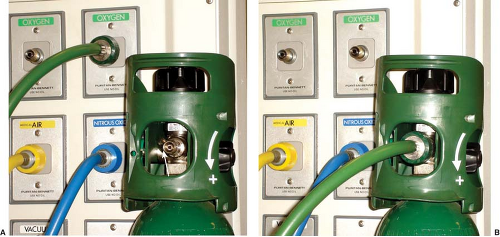 Figure 24.9. A. 3,000 psig E-cylinder valve showing 50 psig DISS connection (arrow) that (B) could be connected to the machine oxygen hose if wall oxygen supply fails. |
Nitrous oxide from the tank supply enters the N2O hanger yoke at pressures of up to 750 psig (at 20°C) and then passes through a regulator that reduces this pressure to 40 to 45 psig (Fig. 38-2). The PISS is designed to ensure that only a N2O tank may hang in a N2O hanger yoke. As with oxygen, a check valve in each yoke prevents the back leakage of N2O if no tank is hanging in the yoke.
The N2O pipeline is supplied from a bulk storage container of liquid N2O or from banks of large N2O tanks, usually H cylinders. (Each H cylinder of N2O evolves 16,000 L of gas at atmospheric pressure.) The pressure in the N2O pipeline is regulated to approximately 50 psig to supply the outlets in the operating room. Having entered the anesthesia machine intermediate-pressure system, N2O must flow past the “fail-safe” valve to reach the N2O flow-control.
Machine Intermediate-Pressure System
Having entered the anesthesia machine’s intermediate-pressure system from the pipeline supply at ∼50 psig, or from the tank supply at 45 psig, oxygen can take several paths:
To the DISS auxiliary oxygen takeoff, which can be connected to a Sanders type jet ventilating system
To supply a pneumatically powered bellows ventilator
Via a regulator and an auxiliary oxygen flowmeter to be connected to a nasal cannula, self-inflating resuscitation bag, etc.
To the oxygen low-pressure alarm sensor
To the pressure sensitive shutoff (“fail-safe”) valve
To the oxygen flush control valve
To the oxygen flowmeter (in some machines via a second-stage regulator)
Oxygen Supply Pressure Failure Safety Devices
The 2000 ASTM F1850-00 standard states, “The anesthesia gas supply device shall be designed so that whenever oxygen supply pressure is reduced to below the manufacturer specified minimum, the delivered oxygen concentration shall not decrease below 19% at the common gas outlet.”48 Contemporary anesthesia machines have a number of safety devices that act together in a cascade manner to minimize the risk of delivery of a hypoxic gas mixture as oxygen pressure decreases. Several of these devices are described in the following sections.
Pneumatic and Electronic Alarm Devices
Many older anesthesia machines have a pneumatic alarm device that provides an audible warning when the oxygen supply pressure decreases to a predetermined threshold value such as 30 psig. The 2000 ASTM F1850-00 standard mandated that a medium priority alarm be activated within 5 seconds when the oxygen pressure decreases below a manufacturer-specific pressure threshold.48 Electronic alarm devices are now used to meet this guideline.
Oxygen Failure Cutoff (“Fail-Safe”) Valves
section) or ones whose system may be disabled by the user can deliver a hypoxic mixture under normal working conditions. On such a system, the oxygen flow-control valve can be closed intentionally or accidentally. Normal oxygen pressure will keep other gas lines open so that a hypoxic mixture could result.32,33
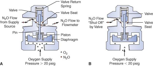 Figure 24.10. Pressure-sensor shutoff valve. The valve is open in A because the oxygen supply pressure is greater than the threshold value of 20 psig. The valve is closed in B because of inadequate oxygen pressure. (Redrawn with permission from: Bowie E, Huffman LM. The Anesthesia Machine: Essentials for Understanding. Madison, WI, Ohmeda, a division of BOC Health Care, Inc., 1985.) |
Many Datex-Ohmeda machines are equipped with a fail-safe valve known as the pressure-sensor shutoff valve (Fig. 24-10). On older machines, this valve operates in a threshold manner and is either open or closed. Oxygen supply pressure opens the valve, and the valve return spring closes the valve. Figure 24-10 shows a nitrous oxide pressure-sensor shutoff valve with a threshold pressure of 20 psig. In Figure 24-10A, an oxygen supply pressure greater than 20 psig is exerted on the mobile diaphragm. This pressure moves the piston and pin upward and the valve opens. Nitrous oxide flows freely to the nitrous oxide flow-control valve. In Figure 24-10B, the oxygen supply pressure is less than 20 psig, and the force of the valve return spring completely closes the valve.32 Nitrous oxide flow stops at the closed fail-safe valve, and it does not advance to the nitrous oxide flow-control valve.
In the GE Datex Aestiva/5, which is a more recent model machine, the “fail-safe” valve is not of an “open or closed” design, rather it is a variable valve in a balance regulator. The balance regulator works as follows. The second-stage pressure regulator for oxygen reduces the pressure to about 30 psig in the intermediate-pressure system. The oxygen pressure is then piloted to the balance regulator where it is applied to the oxygen side of the regulated diaphragm. If the pressure of oxygen is sufficient, the diaphragm pushes against a mechanism that opens the flow pathway for nitrous oxide. If the oxygen piloting pressure decreases, the mechanism begins to close off the pathway for nitrous oxide in proportion to the decrease in piloted oxygen pressure. The balance regulator for nitrous oxide closes completely when the pressure of oxygen falls to 0.5 psig. Balance regulators for heliox and CO2 interrupt the flows of these gases when the piloted oxygen pressure falls below 10 psig.26
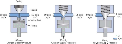 Figure 24.11. Oxygen Failure Protection Device/Sensitive Oxygen Ratio Controller (OFPD/S-ORC), which responds proportionally to changes in oxygen supply pressure. (Redrawn with permission from: Narkomed 2A Anesthesia System: Technical Service Manual. 6th ed. Telford, PA: North American Dräger; 1985.) |
Dräger Medical uses a different fail-safe valve known as the Oxygen Failure Protection Device (OFPD) to interface the oxygen pressure with that of other gases, such as nitrous oxide or inert gases. Similar in principle to the balance regulator described in the previous paragraph, the OFPD is based on a proportioning principle rather than a threshold principle. The pressure of all gases controlled by the OFPD will decrease in proportion with the oxygen pressure. The OFPD consists of a seat-nozzle assembly connected to a spring-loaded piston (Fig. 24-11). The oxygen supply pressure in the left panel of Figure 24-11 is 50 psig. This pressure pushes the piston upward, forcing the nozzle away from the valve seat. Nitrous oxide and/or other gases advance toward the flow control valve at 50 psig. The oxygen pressure in the right panel is 0 psig. The spring is expanded and forces the nozzle
against the seat, preventing flow through the device. Finally, the center panel shows an intermediate oxygen pressure of 25 psig. The force of the spring partially closes the valve. The nitrous oxide pressure delivered to the flow control valve is 25 psig. There is a continuum of intermediate configurations between the extremes (0 to 50 psig) of oxygen supply pressure. These intermediate valve configurations are responsible for the proportional nature of the OFPD. An important concept to be understood with these particular fail-safe devices is that the older Datex-Ohmeda Pressure Sensor Shutoff Valve is threshold in nature (all-or-nothing), whereas the GE balance regulator and Dräger Oxygen Failure Protection Device are variable, flow type proportioning systems.
against the seat, preventing flow through the device. Finally, the center panel shows an intermediate oxygen pressure of 25 psig. The force of the spring partially closes the valve. The nitrous oxide pressure delivered to the flow control valve is 25 psig. There is a continuum of intermediate configurations between the extremes (0 to 50 psig) of oxygen supply pressure. These intermediate valve configurations are responsible for the proportional nature of the OFPD. An important concept to be understood with these particular fail-safe devices is that the older Datex-Ohmeda Pressure Sensor Shutoff Valve is threshold in nature (all-or-nothing), whereas the GE balance regulator and Dräger Oxygen Failure Protection Device are variable, flow type proportioning systems.
Second-Stage Oxygen Pressure Regulator
Most contemporary GE Datex-Ohmeda workstations have a second-stage oxygen pressure regulator set at a specific value, ranging from 12 to 19 psig. Output from the oxygen flowmeter is constant when the oxygen supply pressure exceeds the threshold (minimal) value. The pressure-sensor shutoff valve of older Datex-Ohmeda machines is set at a higher threshold value (20 to 30 psig) to ensure that oxygen is the last gas flowing if oxygen pressure failure occurs.
Flowmeter Assemblies
The flowmeter assembly (Fig. 24-12) precisely controls and measures gas flow to the common gas outlet. With traditional glass flowmeter assemblies, the flow control needle valve regulates the amount of flow that enters a tapered, transparent flow tube known as a Thorpe tube. The tube is tapered such that it has a small cross-sectional area at its lower (low flow) end, and a larger cross-sectional area at its upper (high flow) end. A mobile indicator float inside the flow tube indicates the amount of flow passing through the associated flow control valve. The quantity of flow is indicated on a scale associated with the flow tube.32,33 Some newer anesthesia workstations have now replaced the conventional glass flow tubes with electronic flow sensors that measure the flow of the individual gases. The flow rate data are then presented in numerical format, graphical format, or a combination of the two. The integration of these “electronic flowmeters” is an essential step in the evolution of the anesthesia workstation if it is to become fully integrated with anesthesia data-capturing systems, such as computerized anesthesia record keepers (or AIMS: anesthesia information management systems).
Operating Principles of Conventional Flowmeters
Opening the flow control needle valve allows gas to travel through the space between the float and the flow tube. This space is known as the annular space (Fig. 24-13). The indicator float hovers freely in an equilibrium position where the upward force resulting from gas flow equals the downward force on the float resulting from gravity at a given flow rate. The float moves to a new equilibrium position in the tube when flow is changed. These flowmeters are commonly referred to as constant pressure variable orifice flowmeters because the pressure decrease across the float remains constant for all positions in the tube.33,49,50
Flow tubes are tapered, with the smallest diameter at the bottom of the tube and the largest diameter at the top. The term variable orifice designates this type of unit because the annular space between the float and the inner wall of the flow tube varies with the position of the float. Flow through the constriction created by the float can be laminar or turbulent, depending on the flow rate (Fig. 24-14). The characteristics of a gas that influence its flow
rate through a given constriction are viscosity (laminar flow) and density (turbulent flow). Because the annular space is tubular, at low flow rates laminar flow is present and viscosity determines the gas flow rate. The annular space simulates an orifice at high flow rates, and turbulent gas flow then depends predominantly on the density of the gas.32,33
rate through a given constriction are viscosity (laminar flow) and density (turbulent flow). Because the annular space is tubular, at low flow rates laminar flow is present and viscosity determines the gas flow rate. The annular space simulates an orifice at high flow rates, and turbulent gas flow then depends predominantly on the density of the gas.32,33
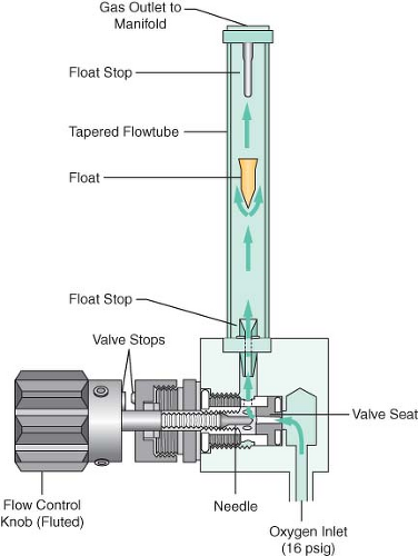 Figure 24.12. Oxygen flowmeter assembly. The oxygen flowmeter assembly is composed of the flow control valve assembly plus the flowmeter subassembly. Note that this is a GE Datex-Ohmeda design because in this figure oxygen is supplied to the flowmeter at 16 psig from a second-stage regulator. (Reproduced with permission from: Bowie E, Huffman LM. The Anesthesia Machine: Essentials for Understanding. Madison, WI: Ohmeda, a division of BOC Health Care, Inc., 1985.) |
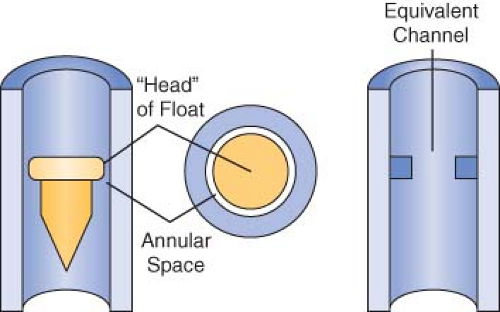 Figure 24.13. The annular space. The clearance between the head of the float and the flow tube is known as the annular space. It can be considered equivalent to a circular channel of the same cross-sectional area. (Redrawn with permission from: Macintosh R, Mushin WW, Epstein HG. Physics for the Anaesthetist. 3rd ed. Oxford: Blackwell Scientific Publications; 1963.) |
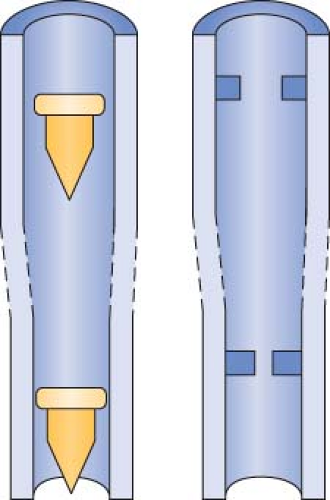 Figure 24.14. Flow tube constriction. The lower half of illustration represents the lower portion of a flow tube. The clearance between the head of the float and the flow tube is narrow. The equivalent channel is tubular because its diameter is less than its length. Viscosity is dominant in determining gas flow rate through this tubular constriction. The upper half of illustration represents the upper portion of a flow tube. The equivalent channel is orificial because its length is less than its width. Density is dominant in determining gas flow rate through this orificial constriction. (Redrawn with permission from: Macintosh R, Mushin WW, Epstein HG. Physics for the Anaesthetist. 3rd ed. Oxford: Blackwell Scientific Publications; 1963.) |
Components of the Flowmeter Assembly
Flow Control Valve Assembly
The flow control valve (see Fig. 24-10) assembly consists of a flow control knob, a needle valve, a valve seat, and a pair of valve stops.32 The assembly can receive its pneumatic input either directly from the pipeline source (50 psig) or from a second-stage pressure regulator. The location of the needle valve in the valve seat changes to establish different orifices when the flow control valve is adjusted. Gas flow increases when the flow control valve is turned counterclockwise, and it decreases when the valve is turned clockwise. Extreme clockwise rotation may result in damage to the needle valve and valve seat. Therefore, flow control valves are equipped with valve “stops” to prevent this occurrence.33
Safety Features
Contemporary flow-control valve assemblies have numerous safety features. The oxygen flow-control knob is physically distinguishable from other gas knobs. It is distinctively fluted, projects beyond the control knobs of the other gases, and is larger in diameter than the flow control knobs of other gases. All knobs are color coded for the appropriate gas, and the chemical formula or name of the gas is permanently marked on each. Flow control knobs are recessed or protected with a shield or barrier to minimize accidental change from a preset position. If a single gas has two flow tubes, the tubes are arranged in series and are controlled by a single flow-control valve.48
In many of the new anesthesia workstations, the flowmeters have been replaced by electronic control panels that contain “soft keys.” In order to adjust any gas flow, the operator must perform the following steps: (1) select and press the “soft key” to identify the gas and anesthetic agent selected; (2) turn the selector knob to adjust the desired flow level; and (3) press the selector knob again to confirm the selected flow level and anesthetic agent (see Electronic Flowmeters section).
Flowmeter Subassembly
The flowmeter subassembly (see Fig. 24-12) consists of the flow tube, the indicator float with float stops, and the indicator scale.33
Flow Tubes
Contemporary flow tubes are made of glass. Most have a single taper in which the inner diameter of the flow tube increases uniformly from bottom to top. Manufacturers provide double flow tubes for oxygen and nitrous oxide to provide better visual discrimination at low flow rates. A fine flow tube indicates flow from approximately 200 mL/min to 1 L/min, and a coarse flow tube indicates flow from approximately 1 mL/min to 10 or 12 L/min. The two tubes are connected in series and supplied from a single flow-control valve. The total gas flow is that shown on the higher flowmeter.
Indicator Floats and Float Stops
Contemporary anesthesia machines use several different types of bobbins or floats, including plumb-bob floats, rotating skirted floats, and ball floats. Flow is read at the top of plumb-bob and skirted floats and at the center of the ball on the ball-type floats.33 Flow tubes are equipped with float stops at the top and bottom of the tube. The upper stop prevents the float from ascending to the top of the tube and plugging the outlet. It also ensures that the float will be visible at maximum flows instead of being hidden in the manifold. The bottom float stop provides a central foundation for the indicator when the flow control valve is turned off.32,33
Scale
The flowmeter scale can be marked directly on the flow tube or located to the right of the tube.48 Gradations corresponding to equal increments in flow rate are closer together at the top of the scale because the annular space increases more rapidly than does the internal diameter from bottom to top of the tube. Rib guides are used in some flow tubes with ball-type indicators to minimize this compression effect. They are tapered glass ridges that run the length of the tube. There are usually three rib guides that are equally spaced around the inner circumference of the tube. In the presence of rib guides, the annular space from the bottom to the top of the tube increases almost proportionally with the internal diameter. This results in a nearly linear scale.33 Rib guides are employed on many Dräger Medical flow tubes.
Safety Features
The flowmeter subassemblies for each gas on the Datex-Ohmeda Modulus I, Modulus II, Modulus II Plus, CD, and Aestiva are housed in independent, color-coded, pin-specific modules. The flow tubes are adjacent to a gas-specific, color-coded backing. The flow scale and the chemical formula (or name of the gas) is permanently etched on the backing to the right of the flow tube. Flowmeter scales are individually hand-calibrated using the specific float to provide a high degree of accuracy. The
tube, float, and scale make an inseparable unit. The entire set must be replaced if any component is damaged.
tube, float, and scale make an inseparable unit. The entire set must be replaced if any component is damaged.
Dräger Medical does not use a modular system for the flowmeter subassembly. The flow scale, the chemical symbol, and the gas-specific color codes are etched directly onto the flow tube. The scale in use is obvious when two flow tubes for the same gas are used.
Problems with Flowmeters
Leaks
Flowmeter leaks are a substantial hazard because the flowmeters are located downstream from all machine safety devices except the oxygen analyzer.51 Leaks can occur at the O-ring junctions between the glass flow tubes and the metal manifold or in cracked or broken glass flow tubes, the most fragile pneumatic component of the anesthesia machine. Even though gross damage to conventional glass flow tubes is usually apparent, subtle cracks and chips may be overlooked, resulting in errors of delivered flows.52 The use of electronic flowmeters and the removal of conventional glass flow tubes from some newer anesthesia workstations (e.g., Datex-Ohmeda S/5 ADU and the Dräger Fabius) may help to eliminate these potential sources of leaks (see Electronic Flowmeters section).
Eger et al.53 demonstrated that, in the presence of a flowmeter leak, a hypoxic mixture is less likely to occur if the oxygen flowmeter is located downstream from all other flowmeters. Figure 24-15 is an updated version of the figure in Eger’s original publication. The unused airflow tube has a large leak. Nitrous oxide and oxygen flow rates are set at a ratio of 3:1. A potentially dangerous arrangement is shown in Figures 24-15A and 24-15B because the nitrous oxide flowmeter is located in the downstream position. A hypoxic mixture can result because a substantial portion of oxygen flow passes through the leak, and all nitrous oxide is directed to the common gas outlet. Safer configurations are shown in Figures 24-15C and 24-15D. The oxygen flowmeter is located in the downstream position. A portion of the nitrous oxide flow escapes through the leak, and the remainder goes toward the common gas outlet. A hypoxic mixture is less likely because all the oxygen flow is advanced by the nitrous oxide. On most Dräger workstations the flowmeters are arranged as in Figure 24-15C, and GE Datex-Ohmeda flowmeters are as in Figure 24-15D.
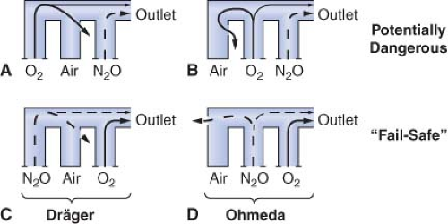 Figure 24.15. Flowmeter sequence—a potential cause of hypoxia. In the event of a flowmeter leak, a potentially dangerous arrangement exists when nitrous oxide is located in the downstream position (A and B). The safest configuration exists when oxygen is located in the downstream position (C and D). See text for details. (Modified with permission from: Eger EI 2nd, Hylton RR, Irwin RH, et al. Anesthetic flowmeter sequence—a cause for hypoxia. Anesthesiology. 1963;24:396.) |
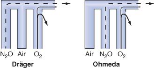 Figure 24.16. Oxygen flow tube leak. An oxygen flow tube leak can produce a hypoxic mixture regardless of flow tube arrangement. (Reproduced with permission from: Brockwell RC. Inhaled anesthetic delivery systems. In: Miller RD, ed. Anesthesia. 6th ed. Philadelphia, PA: Churchill Livingstone; 2004:281.) |
A leak in the oxygen flow tube may result in creation of a hypoxic mixture even when oxygen is located in the downstream position (Fig. 24-16).51,52 Oxygen escapes through the leak and nitrous oxide continues to flow toward the common outlet, particularly at high ratios of nitrous oxide to oxygen flow.
Inaccuracy
Flow measurement error can occur even when flowmeters are assembled properly with appropriate components. Dirt or static electricity can cause a float to stick, and the actual flow may be higher or lower than that indicated. Sticking of the indicator float is more common in the low flow ranges because the annular space is smaller. A damaged float can cause inaccurate readings because the precise relationship between the float and the flow tube is altered. Back pressure from the breathing circuit can cause a float to drop so that it reads less than the actual flow. Finally, if flowmeters are not aligned properly in the vertical position (plumb), readings can be inaccurate because tilting distorts the annular space.24,33,52
Ambiguous Scale
Before the standardization of flowmeter scales and the widespread use of oxygen analyzers, at least two deaths resulted from confusion created by ambiguous scales.24,52,54 The operator read the float position beside an adjacent but erroneous scale in both cases. Today this error is less likely to occur because contemporary flowmeter scales are marked either directly onto the flow tube or immediately to the right of it.48 The possibility of confusion is minimized when the scale is etched directly onto the tube.
Electronic Flowmeters
Newer anesthesia workstations such as the GE-Datex-Ohmeda S/5 ADU, the Dräger Fabius GS, and the Dräger Apollo (among others) have conventional flow control knobs and flow control valves, but have electronic flow sensors and digital displays rather than glass flow tubes (Fig. 24-17). The output from the flow control valve is represented graphically and/or numerically in liters per minute on the workstation’s integrated user interface. These systems are dependent on electrical power to provide a precise display of gas flows. However, even when electrical power is totally interrupted, since the flow control valves themselves are mechanical (i.e., non-electronic), the set gas flows will continue uninterrupted. Since these machines do not have individual flow tubes that physically quantitate the flow of each gas, a small conventional pneumatic “fresh gas” or “total flow” indicator is also provided that
gives the user an estimate of the total quantity of fresh gas flowing from all gas flow-control valves to the anesthesia workstation’s common gas outlet, and is functional even in the event of a total power failure (Fig. 24-18).
gives the user an estimate of the total quantity of fresh gas flowing from all gas flow-control valves to the anesthesia workstation’s common gas outlet, and is functional even in the event of a total power failure (Fig. 24-18).
 Figure 24.17. Datex S5/ADU. Note mechanical needle valve controls for the gas flows but electronic display of virtual flowmeter and digital readout. |
In the GE Datex Aisys Carestation, the traditional needle valve gas flow controls and color-coded control knobs are replaced by an electronic control system that uses a gas mixer. In the GE Aisys Carestation, the second gas, either N2O or air is first selected, followed by the desired inspired oxygen concentration (FIO2) and total FGF. Total flow and FIO2 selections are made by pressing soft keys on the control panel, adjusting the settings using a “com wheel,” and then pressing the com wheel to “confirm.”
In the Aisys Carestation, the controls to increase or decrease flows (or agent concentration) represent a departure from the traditional. The traditional needle valve gas flow controls were designed by mechanical engineers so that one turns the flow control knob counterclockwise to increase flow (by opening the valve wider). The same applies to increasing agent concentration on a variable bypass vaporizer. The Aisys Carestation controls are designed by electrical engineers where the standard is to increase the output by rotating the dial (com wheel) in a clockwise direction. Thus when learning to use the Aisys Carestation workstation, the operator must adapt to “clockwise to increase” and remember to confirm new settings, otherwise they are not implemented. In the event the gas mixer fails, the Aisys Carestation will switch to a backup system that permits delivery of oxygen to the breathing system via an Alternate Oxygen flowmeter, which is a traditional mechanical needle valve and rotameter flow tube.
 Figure 24.18. Dräger Fabius GS. Note needle valve controls, graphical and digital flow displays. The total gas flow rotameter continues to function if electrical power is lost. |
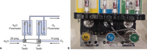 Figure 24.19. A. Schematic and (B) photo of Ohmeda Link-25 Proportion-Limiting Control System. See text for details. |
Proportioning Systems
GE-Datex-Ohmeda Link-25 Proportion-Limiting Control System
Traditional GE-Datex-Ohmeda machines use the Link-25 System. The heart of the system is the mechanical integration of the nitrous oxide and oxygen flow-control valves. It allows independent adjustment of either valve, yet automatically intercedes to maintain a minimum 25% oxygen concentration with a maximum nitrous oxide–oxygen flow ratio of 3:1. The Link-25 automatically increases oxygen flow to prevent delivery of a hypoxic mixture.
Figure 24-19 illustrates the GE-Datex-Ohmeda Link-25 System. The nitrous oxide and oxygen flow-control valves are identical. A 14-tooth sprocket is attached to the nitrous oxide flow-control valve, and a 29-tooth sprocket is attached to the oxygen flow-control valve. A stainless steel chain physically links the sprockets. When the nitrous oxide flow-control valve is turned through 2.09 revolutions, or 29 teeth, the oxygen flow-control valve will revolve once because of the gear ratio. The final 3:1 flow ratio results because the nitrous oxide flow-control valve is supplied with nitrous oxide at a pressure of approximately 26 psig from a second-stage N2O regulator, whereas the oxygen flow-control valve is supplied by a second-stage regulator at 14 psig. The combination of the mechanical and pneumatic aspects of the system yields the final minimum 25% oxygen concentration. The GE-Datex-Ohmeda Link-25 proportioning system increases oxygen flow when nitrous oxide flow would be excessive by opening the O2 needle valve more. Conversely, if the oxygen flow is decreased such that the nitrous oxide flow would be excessive, it acts to decrease the flow of N2O by physically decreasing the opening of the nitrous oxide needle valve.
Dräger Oxygen Ratio Monitor Controller/Sensitive Oxygen Ratio Controller System
Dräger’s proportioning system, the Oxygen Ratio Monitor Controller (ORMC), is used on the North American Dräger Narkomed 2A, 2B, 3, and 4 machines. An equivalent system used on some more recent Dräger workstations such as the Fabius GS, Narkomed 6000 series, and the Apollo is known as the Sensitive Oxygen Ratio Controller (S-ORC). The ORMC and the S-ORC are pneumatic oxygen–nitrous oxide interlock systems designed to maintain a fresh gas oxygen concentration of at least 25 ± 3% when nitrous oxide is used. They control the fresh gas oxygen concentration to levels substantially greater than 25% when the oxygen flow rate is <1 L/min. The ORMC and S-ORC limit nitrous oxide flow to prevent delivery of a hypoxic mixture by decreasing the supply pressure of nitrous oxide to its flow control needle valve. This is unlike the Link-25 system, in which the gas supply pressure to the nitrous oxide needle valve is held constant (by the second-stage regulator) and gas flow changes are made by physically changing the size of the needle valve opening.
A schematic of the ORMC is shown in Figure 24-20. It consists of an oxygen chamber, a nitrous oxide chamber, and a nitrous oxide slave control valve. All are interconnected by a mobile horizontal shaft. The pneumatic input into the device is from the oxygen and the nitrous oxide flowmeters. These flowmeters are unique because they have specific resistors located downstream from the flow control valves. These resistors create back pressures directed to the oxygen and nitrous oxide chambers. The value of the oxygen flow tube resistor is 3 to 4 times that of the nitrous oxide flow tube resistor, and the relative value of these resistors determines the value of the controlled fresh gas oxygen concentration. The back pressures in the oxygen and nitrous oxide chambers are applied against rubber diaphragms attached to the mobile horizontal shaft. Movement of the shaft adjusts the opening of the nitrous oxide slave control valve, which in turn adjusts the feed pressure of the nitrous oxide flow control needle valve.
If the oxygen flow, and therefore back pressure, is proportionally higher than the nitrous oxide back pressure, the nitrous oxide slave control valve opens more widely, increasing the pressure of nitrous oxide upstream of the nitrous oxide flow-control needle valve, which results in an increase in nitrous oxide flow. As the nitrous oxide flow is increased manually, the nitrous oxide back pressure forces the shaft rightward toward the oxygen chamber. The nitrous oxide slave control valve opening becomes more
restrictive and limits the nitrous oxide supply pressure to the flowmeter, which decreases the nitrous oxide flow.
restrictive and limits the nitrous oxide supply pressure to the flowmeter, which decreases the nitrous oxide flow.
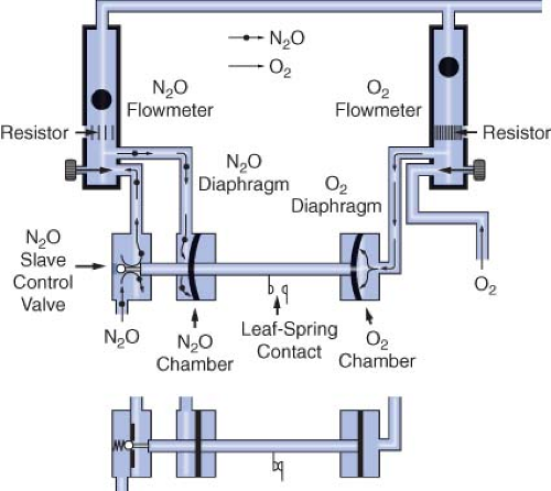 Figure 24.20. Dräger Oxygen Ratio Monitor Controller. See text for details. (Redrawn with permission from: Schreiber P. Safety Guidelines for Anesthesia Systems. Telford, PA: North American Dräger; 1984.) |
Figure 24-20 illustrates the action of a single ORMC/S-ORC under different sets of circumstances. The back pressure exerted on the oxygen diaphragm, in the upper configuration is greater than that exerted on the nitrous oxide diaphragm. This causes the horizontal shaft to move to the left, opening the nitrous oxide slave control valve. Nitrous oxide is then able to proceed to its flow control valve and out through the flowmeter. In the lower configuration, the nitrous oxide slave control valve is closed because of inadequate oxygen back pressure.34 To summarize, in contrast to the GE-Datex-Ohmeda Link-25 System which actively increases oxygen flow to maintain a fresh gas oxygen concentration ≥25%, the Dräger ORMC and S-ORC are systems that limit nitrous oxide flow to prevent delivery of a fresh gas mixture with an oxygen concentration ≤25%.
Limitations
N2O/O2 proportioning systems are not foolproof. Workstations equipped with these systems can still deliver a hypoxic mixture under certain conditions. Following is a description of some of the situations in which this may occur.
Wrong Supply Gas
Both the GE-Datex-Ohmeda Link-25 and the Dräger ORMC/S-ORC will be defeated if a gas other than oxygen is present in the oxygen pipeline and will allow delivery of hypoxic gas mixtures. In the Link-25 System, the nitrous oxide and oxygen flow-control valves will continue to be mechanically linked. Nevertheless, a hypoxic mixture can proceed to the common gas outlet. In the case of the Dräger ORMC or S-ORC, the rubber diaphragm for oxygen will reflect adequate supply pressure on the oxygen side even though the incorrect gas is present, and flow of both the wrong gas plus nitrous oxide will result. The oxygen analyzer is the only workstation monitor besides an integrated multigas analyzer that would detect this condition in either system.
Defective Pneumatics or Mechanics
Normal operation of the Datex-Ohmeda Link-25 and the Dräger ORMC/S-ORC is contingent on pneumatic and mechanical integrity.58 Pneumatic integrity in the Datex-Ohmeda system requires properly functioning second-stage regulators. A nitrous oxide:xygen ratio other than 3:1 may result if the regulators are not precise. The chain connecting the two sprockets must be intact—if the chain is cut or broken, a 97% nitrous oxide concentration can result.59 In the Dräger System, a functional OFPD is necessary to supply appropriate pressure to the ORMC. The mechanical aspects of the ORMC/S-ORC, such as the rubber diaphragms, the flow tube resistors, and the nitrous oxide slave control valve, must likewise be intact.
Leaks Downstream
The ORMC/S-ORC and the Link-25 function at the level of the flow control valves. A leak downstream from these devices, such as a broken oxygen flow tube (see Fig. 24-16), can result in delivery of a hypoxic mixture to the common gas outlet. In this situation, oxygen escapes through the leak and the predominant gas delivered is nitrous oxide. The oxygen monitor and/or integrated multigas analyzer are the only machine safety devices that can detect this problem.51 For the majority of its products, Dräger Medical recommends a pre-use positive-pressure leak test to detect such a leak. However, in addition to this test, for many Dräger machines, application of the negative-pressure leak test as well may provide a more sensitive method to detect such a leak. Datex-Ohmeda almost universally recommends a pre-use negative-pressure leak test for its workstations, because of the frequently present check valve located at the common gas outlet (see Checking Your Anesthesia Workstation section).
Inert Gas Administration
Administration of a third inert gas, such as helium, nitrogen, or carbon dioxide, can cause a hypoxic mixture because contemporary proportioning systems link only nitrous oxide and oxygen.60 Use of an oxygen analyzer to monitor the inspired oxygen concentration is mandatory (or a multigas analyzer when available) if the operator uses a third gas.
Dilution of Inspired Oxygen Concentration by Potent Inhaled Volatile Anesthetics
Volatile inhaled anesthetics are added to the mixed gases downstream from both the flowmeters and the proportioning system. Concentrations of less-potent inhaled anesthetics such as desflurane (MAC ∼ 7%) may account for a larger percentage of the total fresh gas composition than more potent agents such as isoflurane (MAC ∼ 1.2%). This can be seen when the maximum vaporizer concentration dial settings of the various volatile agents are examined (e.g., desflurane maximum dial setting of 18% vs. isoflurane maximum dial setting of 5%). Since significant percentages of these inhaled anesthetics may be added downstream of the proportioning system, the resulting gas/vapor mixture may contain an inspired oxygen concentration that is <21%. Awareness of this possibility, particularly when high concentrations of desflurane are used, is essential.
Oxygen Flush Valve
low-pressure circuit downstream from the vaporizers and, most importantly, downstream from any outlet check valve, if present. The spring-loaded oxygen flush valve remains closed until the operator opens it by depressing the oxygen flush button. Actuation of the valve delivers 100% oxygen at a flow of 35 to 75 L/min to the breathing circuit.32
The oxygen flush valve can provide a “high pressure” oxygen source that might be used for jet ventilation under the following circumstances: (1) the anesthesia machine is equipped with a one-way check valve positioned between the vaporizers and the oxygen flush valve; and (2) when a positive-pressure relief valve exists downstream from the vaporizers. The pressure relief valve must be upstream of the outlet check valve. Because the Ohmeda Modulus II has such a one-way check valve and its low-pressure system positive-pressure relief valve is upstream from the outlet check valve, the entire oxygen flow of 35 to 75 L/min is delivered to the common gas outlet at a pressure of 45 to 50 psig. On the other hand, the Ohmeda Modulus II Plus and some Ohmeda Excel machines are not capable of functioning as an appropriate oxygen source for jet ventilation. The Ohmeda Modulus II plus, which does not have the check valve, provides only 7 psig at the common gas outlet because much of the oxygen flows retrograde into the low-pressure circuit and out to atmosphere through an internal relief valve located upstream from the oxygen flush valve. The Ohmeda Excel 210, which does have a one-way check valve, also has a positive-pressure relief valve downstream from the check valve and therefore is unsuitable for jet ventilation. Older North American Dräger machines such as the Narkomed 2A (which also does not have the outlet check valve) produce a pressure of 18 psig at the common gas outlet because oxygen is vented to atmosphere through a pressure relief valve located in the Dräger Vapor vaporizers.61
It must be emphasized that use of the oxygen flush to drive a jet ventilation system connected at the machine’s common gas outlet is an “off label” use of the machine, and is not recommended by the machine manufacturers. If jet ventilation is required, a purpose-built Sanders type system should be used, connected to a 50 psig oxygen source.
Several hazards have been reported with use of the oxygen flush valve. A defective or damaged valve can stick in the fully open position, resulting in barotrauma.62 A valve sticking in a partially open position can result in patient awareness during general anesthesia, because the oxygen flow from the incompetent valve dilutes the inhaled anesthetic.28 Improper use of normally functioning oxygen flush valves also can result in problems. Overzealous intraoperative oxygen flushing can dilute inhaled anesthetics. Oxygen flushing during the inspiratory phase of positive-pressure ventilation can produce barotrauma in patients if the anesthesia machine does not incorporate fresh gas decoupling or an appropriately adjusted inspiratory pressure limiter. Anesthesia systems (Dräger Narkomed 6000 series, Julian, Fabius GS, and Datascope Anestar) with fresh gas decoupling are inherently safer from the standpoint of minimizing the chance of producing barotrauma from inappropriate oxygen flush valve use. These systems physically separate the fresh gas inflow from either the flowmeters or the oxygen flush valve, from the delivered tidal volume presented to the patient’s lungs (see Fresh Gas Decoupling section). With traditional anesthesia breathing circuits, excess volume cannot be vented during the inspiratory phase of mechanical ventilation because the ventilator pressure relief valve is closed and the APL valve is either out-of-circuit or closed.63 An alternative solution to this problem is used in the GE-Datex-Ohmeda S/5 ADU and GE-Aestiva. The breathing systems on these machines utilize an integrated adjustable pressure limiter. If this device is properly adjusted, it functions like the APL (or pop-off) valve to limit the maximum airway pressure to a safe level, thereby reducing the possibility of barotrauma.
Some very old anesthesia systems made use of a freestanding vaporizer downstream from the common gas outlet; on these systems, oxygen flushing could rapidly deliver dangerously large quantities of inhaled anesthetic to the patient. Finally, inappropriate use of the oxygen flush to evaluate the low-pressure circuit for leaks can be misleading, particularly on GE Datex-Ohmeda machines with a one-way check valve at the common gas outlet.27 Since back pressure from the breathing circuit closes the one-way check valve gas-tight, major low-pressure circuit leaks can go undetected with this leak test (see Checking Your Anesthesia Workstation section).
Web-Based Anesthesia Software Simulation, the Virtual Anesthesia Machine
The advances in web-based application technology, as well as trends to incorporate simulation into anesthesia training and education, have generated development of online anesthesia simulation resources. The Virtual Anesthesia Machine (VAM) is a web-based anesthesia simulation environment (Fig. 24-21) that provides information on the function of anesthesia machines along with tutorials and operational scenarios, including failure modes of new and traditional anesthesia workstations.64 It is available for use free of charge. The VAM allows the user to adjust most of the controls found on a modern anesthesia workstation: gas flows, ventilator settings, etc. The authors of the VAM, in collaboration with the Anesthesia Patient Safety Foundation (APSF), have created the Anesthesia Machine Workbook (AMW). The AMW provides additional information and tutorials covering six anesthesia machine subsystems: the high-pressure system, the low-pressure system, the breathing circuit, manual ventilation, mechanical ventilation, and the scavenging system.65
Vaporizers
As dramatically as the evolution of the anesthesia workstation has been in recent years, vaporizers have also changed from rudimentary ether inhalers and the “Copper Kettle” to the temperature-compensated, computer-controlled, and flow-sensing devices in use today. In 1993, with the introduction of desflurane to the clinical setting, an even more sophisticated vaporizer was introduced to handle the unique physical properties of this agent. Now, a new generation of anesthesia vaporizers blending traditional technology and “new” computerized control technology has emerged in the GE-Datex Aladin cassette vaporizer system. Before proceeding with a discussion of variable bypass vaporizers, the Datex-Ohmeda Tec 6 desflurane vaporizer and the Datex-Ohmeda Aladin cassette vaporizer, it is important to review certain physical principles to facilitate understanding of the operating principles, construction, and design of contemporary volatile anesthetic vaporizers.
Physics
Vapor Pressure
Contemporary inhaled volatile anesthetics exist in the liquid state at temperatures below 20°C. When a volatile liquid is in a closed container, molecules escape from the liquid phase to the vapor phase until the number of molecules in the vapor phase is constant. These molecules in the vapor phase bombard the wall of
the container and create a pressure known as the saturated vapor pressure. As the temperature increases, more molecules enter the vapor phase, and the vapor pressure increases (Fig. 24-22). Vapor pressure is independent of atmospheric pressure and is dependent only on the temperature and physical characteristics of the liquid. The boiling point of a liquid is defined as that temperature at which the vapor pressure equals atmospheric pressure.49,66,67 At 760 mm Hg, the boiling points for desflurane, isoflurane, halothane, enflurane, and sevoflurane are approximately 22.8, 48.5, 50.2, 56.5, and 58.5°C, respectively. Unlike other contemporary inhaled anesthetics, desflurane boils at temperatures that may be encountered in particularly warm clinical settings such as pediatric and burn operating rooms. This unique physical characteristic alone mandates a special vaporizer design to control the delivery of desflurane. If agent-specific vaporizers are accidentally filled with incorrect liquid anesthetic agents, the resulting mixtures of volatile agents may demonstrate properties that differ from those of the individual component agents. The altered vapor pressure and other physical properties of the mixtures that result from the mixing of various agents may alter the output of the vaporizer (see Variable Bypass Vaporizers: Misfilling section).68
the container and create a pressure known as the saturated vapor pressure. As the temperature increases, more molecules enter the vapor phase, and the vapor pressure increases (Fig. 24-22). Vapor pressure is independent of atmospheric pressure and is dependent only on the temperature and physical characteristics of the liquid. The boiling point of a liquid is defined as that temperature at which the vapor pressure equals atmospheric pressure.49,66,67 At 760 mm Hg, the boiling points for desflurane, isoflurane, halothane, enflurane, and sevoflurane are approximately 22.8, 48.5, 50.2, 56.5, and 58.5°C, respectively. Unlike other contemporary inhaled anesthetics, desflurane boils at temperatures that may be encountered in particularly warm clinical settings such as pediatric and burn operating rooms. This unique physical characteristic alone mandates a special vaporizer design to control the delivery of desflurane. If agent-specific vaporizers are accidentally filled with incorrect liquid anesthetic agents, the resulting mixtures of volatile agents may demonstrate properties that differ from those of the individual component agents. The altered vapor pressure and other physical properties of the mixtures that result from the mixing of various agents may alter the output of the vaporizer (see Variable Bypass Vaporizers: Misfilling section).68
Related posts:


Stay updated, free articles. Join our Telegram channel

Full access? Get Clinical Tree


