Fig. 32.1
Diameter Index Safety System (DISS) (Reprinted with permission from Brockwell and Andrews [1])
32.3 Cylinder Supply Source
Anesthesia machines have reserve E cylinders if a pipeline supply source is not available or if the pipeline fails. O2 tanks are fitted at the factory to a pressure of approximately 2000 psig at room temperature. A full E cylinder of O2 (internal volume of approximately 4.8 L) at a pressure of 2000 psig will produce approximately 660 of gaseous O2 at atmospheric pressure. The cylinder attaches to the machine through the hanger-yoke assembly. The hanger yoke assembly orients and supports the cylinder, provides a gas-like seal, and ensures a unidirectional flow of gases into the machine. Each hanger yoke is equipped with a Pin Index Safety System (PISS). The PISS is a safeguard introduced to eliminate cylinder interchanging. Each gas or combination of gases has a specific pin arrangement. A check valve is located downstream from each cylinder. The check valve has several functions. First, it minimizes gas transfer from a cylinder at a high pressure to one with lower pressure. Second, it allows an empty cylinder to be exchanged for a full one while gas flow continues from the other cylinder into the machine with minimal loss of gas. Third, it minimizes leakage from an open cylinder to the atmospheres if one cylinder is absent. The check valves may leak; therefore if a yoke does not have a tank hanging on it, a yoke plug should be inserted. This prevents leakage of gas in the event of an incompetent check valve, which might otherwise cause depletion of the O2 tank. The high-input pressure of the cylinder is reduced to 45 psig by the oxygen pressure regulator. Failure of the pressure reduction function of a regulator can transmit excessively high pressure (up to 2200 psig) to the machine’s low-pressure system. To protect against such occurrences, the regulator incorporates a pressure relief valve in the low-pressure chamber in which excess pressures are vented to the atmosphere. The cylinders should be turned off except during the preoperative machine checking period or when pipeline source is unavailable, to avoid depletion of the cylinder (◘ Figs. 32.3, 32.4, and 32.5).
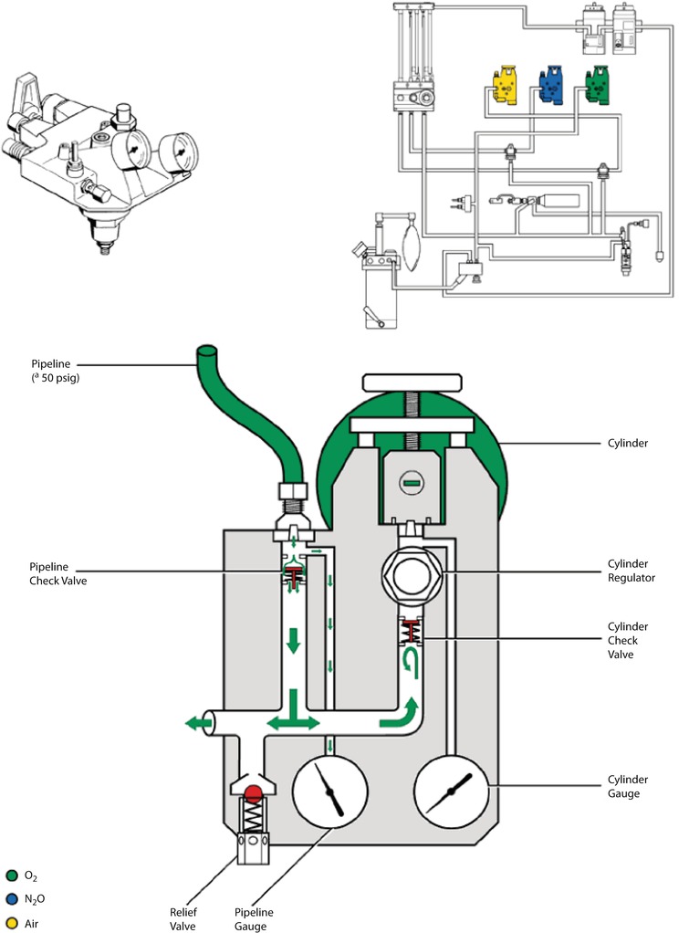
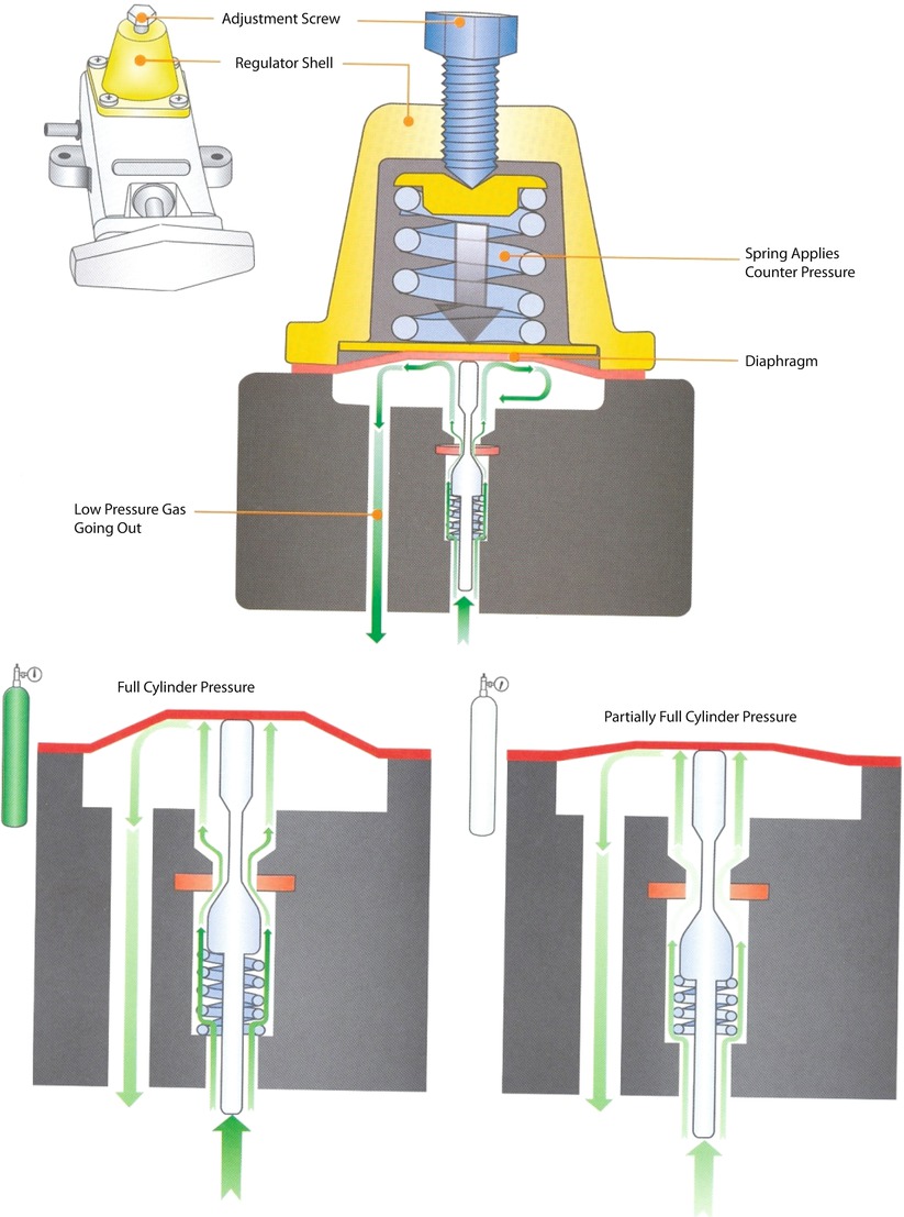
Fig. 32.4
Cylinder attachment to anesthesia machine (Reprinted with permission from Brockwell and Andrews [1])
Fig. 32.5
Pipeline and cylinder systems attachment to the anesthesia machine. Pipeline pressure is a nominal 50 psi. As gas enters the gas supply module the pressure is reflected on the pipeline gauge located on the front panel of the machine. A check valve on the cylinder side prevents gas from flowing out the cylinder connection when the pipeline gas supply is being used; and a check valve on the pipeline side when the cylinder is being used. The regulator will regulate the pressure from the cylinder to 45 PSI for O2. (© GE HealthCare. Reprinted by permission)
32.4 Safety Devices of Oxygen Supply Pressure Failure
The 2000 ASTM F 1850-00 standard states, “The anesthesia gas supply device shall be designed so that whenever O2 supply pressure is reduced to below the manufacturer specific minimum, the delivered O2 concentration shall not decrease below 19% at the common gas outlet.” If the oxygen pressure in the high-pressure system decreases (usually to <30 psig), an oxygen supply alarm is activated within 5 s.
32.5 Fail-Safe Valves
In Datex-Ohmeda machines, when the oxygen pressure in the machine’s high pressure system falls below 20 psig, the flow of N2O and all other gases to their flow-control valves is interrupted. This valve is an all-or-nothing valve; it opens at oxygen pressures of 20 psig or more and is closed at pressures less than 20 psig (◘ Fig. 32.6). The fail-safe valve in the North American Dräger Narkomed machines (Dräger, Lübeck, Germany) is called the oxygen failure protection device (OFPD). There is 1 OFPD for each of the gases supplied to the machine. As the oxygen supply pressure decreases, the OFPD proportionately reduces the supply pressure of each of the other gases to their flow-control valves. The supply of N2O and other gases is completely interrupted when O2 supply pressure falls below 12 ± 4 psig (◘ Fig. 32.7).
Fig. 32.6
Safe safety valve in Datex-Ohmeda anesthesia machine
Fig. 32.7
Safe safety valve in North American Dräger machine
32.6 Flow Meter Assemblies
With traditional glass flow meter assemblies, the flow control valve regulates the amount of flow that enters a tapered, transparent flow tube known as a Thorpe tube.
32.6.1 Physical Principles of Conventional Flow Meters
Flow tubes are tapered, with the smallest diameter at the bottom of the tube and the largest at the top. The term “variable orifice” designates this type of unit because the annular space between the float and the inner wall of the flow tube varies with the position of the float. The annular space is tubular (diameter of the space is shorter than its length) at low flow rates, laminar flow is present, and viscosity determines the gas flow rate (Hagen-Poiseuille Equation). The annular space (its diameter of the orifice is almost equal to its length) simulates an orifice at high flow rates, and turbulent gas flow then depends predominately on the density of the gas (Graham’s Law). Of, note the oxygen flow meter can be used for helium at low flow rates as they have the same viscosity (◘ Fig. 32.8). Similarly, the nitrous oxide flow meter can be used for carbon dioxide at high flows as they have the same density.
Fig. 32.8
Annular space between the float and the inner wall of the flow tube. Note the annular space resembles the shape of tube at low flow rates and orifice at high flow rates
32.6.2 Components of Flow Meter Assemblies
Flow Control Valve Assembly
The assembly of the flow control valve is composed of a flow control knob, a needle valve, a valve seat, and a pair of valve steps. The assembly can receive its pneumatic input directly from the pipeline source (50 psig) or from a second-stage pressure regulator. The location of the needle valve in the valve seat changes to establish different orifices when the flow control valve is adjusted. Gas flow increases when the flow control valve is turned counter clockwise, and it decreases when the valve is turned clockwise (◘ Fig. 32.9).
Fig. 32.9
Oxygen flow meter assembly
Safety Features
The O2 flow control knob is larger and physically distinguishable from other gas knobs.
All knobs are color coded for the appropriate gas, and the chemical formula or name of the gas is permanently marked on each.
If a single gas has 2 flow tubes, the tubes are arranged in series and are controlled by a single flow control valve.
The oxygen flow meter should be downstream (close to the patient) to other flow meters to avoid delivering hypoxic mixture in case of leak of the flow meters (◘ Fig. 32.10).
Fig. 32.10
Position of flow meters to avoid delivering hypoxic mixture
Contemporary anesthesia machines use several different types of bobbins or floats including plumb-bob floats, rotating, skirted floats and ball floats. Flow is read at the top of plumb bob and skirted floats and at the center of the ball on the ball-type floats.
Flow tubes are equipped with float stops at the top and bottom of the tube. The upper step stop prevents the float from ascending to the top of the tube and plugging the outlet. It also ensures that the float is visible at maximum flows instead of being hidden in the manifold. The bottom float stop provides a control foundation for the indicator when the flow control valve is turned off. Rib guides are used with ball type floats. The triangular thickening of the inside of the tube keeps the ball centered. The flow meters are calibrated at atmospheric pressure (760 mmHg) at room temperature (20 °C). Variations in temperature as a rule are slight and do not produce significant changes. Pressure variations affect the flow according to the following equation:
Where F1 is the real flow at new pressure, F0 is the flow at sea level atmospheric pressure, do is the density of the gas at sea level atmospheric pressure, and d1 is the density of the gas at the new pressure. So according to this equation, the flow recorded at the flow meters in hyperbaric chamber is lower than the real flow and vice versa at low-pressure settings in high altitudes.
32.7 Proportioning Systems
Nitrous oxide and oxygen are interfaced mechanically or pneumatically so that the minimum oxygen concentration at the common gas outlet is between 23% and 25%, depending on the manufacturer.
32.7.1 Datex-Ohmeda Link -25 Proportion Limiting Control System
In this Datex-Ohmeda system, there is a 14-tooth sprocket on the nitrous oxide flow control valve and a 29-tooth sprocket on the oxygen flow control valve. A pin on the O2 sprocket engages a pin on the O2 flow control knob if the flow control valves are adjusted so that 25% concentration of O2 is reached. This causes the O2 and N2O flow control valves to turn together to maintain a minimum of 25% O2. The proportioning of N2O to O2 (75–25%) is completed because the N2O flow control valve is supplied from a second stage regulator that reduces N2O pressure to 26 psig before it reaches the flow control valve. The O2 flow control is supplied at a pressure of 14 psig from a second stage O2 regulator. This minimum O2 ratio device permits independent control of each gas as long as the percentage of O2 is above the minimum. It should be rated that these devices only link 2 gases: nitrous oxide and oxygen (◘ Fig. 32.11). Administrations of a third gas such as helium can result in a hypoxic mixture.
Fig. 32.11
Datex-Ohmeda Link 25-proportion limiting control system
32.7.2 North American Dräger Oxygen Ratio Monitor Controller
North American Drägers’ proportioning system, the oxygen ratio monitor controller (ORMC) is used in the North American Dräger machine. The ORMC is a pneumatic oxygen-nitrous oxide interlock system designed to maintain fresh gas O2 concentration of at least 25% ± 3%. ORMC controls the fresh gas oxygen concentration to levels substantially higher than 25% at oxygen flow rates of less than 1 L/min. ORMC limits nitrous oxide flow to prevent delivery of a hypoxic mixture. In this system, the pressure of the oxygen chamber controls the flow of nitrous oxide through the slave valve. If the pressure in oxygen falls, the opening in the slave valve will narrow and decrease nitrous oxide flow. However, if the pressure in the oxygen chamber is high, it will open the sleeve valve and increase nitrous oxide flow (◘ Fig. 32.12).
Fig. 32.12
North American Dräger pneumatic proportion linkage system
32.8 Oxygen Flush Valve
The oxygen flush valve allows direct communication between the oxygen pipeline-pressure systems to the patient circuit. Flow from the oxygen flush valve enters the low-pressure circuit downstream from the vaporizers and downstream from the Datex-Ohmeda machine outlet check valve.
Actuation of the valve delivers 100% oxygen at a rate of 35–75 L/min to the breathing circuit. The oxygen flush valve is associated with several hazards. A defective or damaged valve can stick in a fully open position, resulting in barotraumas. A valve sticking in a partially open position can result in awareness by the patient because the oxygen flow from the incompetent valve dilutes the inhaled anesthetic. Oxygen flushing during the inspiratory phase of positive pressure ventilation can produce barotrauma in patients if the anesthesia machine does not incorporate an appropriately adjusted inspiratory pressure limiter (◘ Figs. 32.13 and 32.14).
Fig. 32.13
Oxygen flush valve
32.9 Waste-Gas Scavenging Systems
The tubing for the scavenging systems has an internal diameter of either 19 mm or 30 mm, compared with the 22-mm anesthesia circuit and ventilator tubing and the 15-mm common gas outlet and tracheal connectors. The scavenging system interfaces with the hospital suction system to remove gas flow from the patient circuit.
32.9.1 Scavenging Systems
Components
Scavenging systems classically have 5 components:
- 1.
The gas collecting assembly.
- 2.
The transfer tubing.
- 3.
The scavenging interface.
- 4.
The gas disposal assembly tubing.
- 5.
An active or passive disposal system.
Gas-Collecting Assembly
The gas-collecting assemblies are the points of waste gas exit from the breathing circuit to the transfer tubing. Waste anesthetic gases are vented from the anesthesia system either through the adjustable pressure-limiting (APL) valve (pop-off valve) or through ventilator relief valve.
Transfer Tubing
The transfer tubing carries excess gas from the gas-collecting assembly to the scavenging interface. The tubing must have 30-mm connectors on either end, which are distinct from the 22-mm connectors on the breathing system tubing. The tubing must be sufficiently rigid to prevent kinking to minimize the chance of occlusion, or it must contain pressure relief in case of occlusion. Occlusion or kinking can increase the pressure in the breathing circuit and barotrauma.
Scavenging Interface
Closed anesthesia systems use spring-loaded valves to ensure that excessively high or low pressures are not applied to the patient circuit. Thus if the systems are not connected to negative pressure (suction), excess pressure in the interface caused by gas entering it from the circuit would first cause distension of the interface reservoir bag, then the excess would be vented via the position pressure-relief valve at about +5 cm H2O. In the event that excessive suction might be applied to the circuit, the reservoir bag would first be sucked empty, and then 1 (Ohmeda interface) or 2 (North American Dräger closed interface) negative pressure-relief (pop-in) valves (−0.25 to −1.80 cm H2O) would open to preferentially draw in room air and minimize the potential application of negative pressure to the patient circuit.
Many contemporary anesthesia machines contain open-reservoir scavenging interfaces, are valveless, and use continually open ports to provide pressure relief. Waste gas from the circuit is directed to the bottom of the canister, and the hospital suction system aspirates gas from the bottom of the canister. Therefore, the vacuum rate should exceed the rate of waste gas flow into the chamber, and some room air should also be drawn into the canister through the relief port. This interface system depends on relief ports for pressure relief, so these ports should remain unoccluded at all times. In addition, if vacuum flow is inadequate, waste gas can spill out into the room through the relief ports.
Collectively, if the valves in a closed interface or the ports in an open interface become occluded, an excess of positive or negative pressure could develop in the circuit.
Gas Disposal Assembly Conduit on Extract Flow
The gas disposal assembly conduit conducts waste gas from the scavenging interface to the receiving end of the gas disposal system. It should be collapsible-proof and should run overhead if possible to minimize the chance of accidental occlusion.
An Active or Passive Disposal System
An active system relies on a hospital central evacuating system to remove gas from the scavenging system. A passive system simply vents the gas into a nonrecirculating heating, ventilation, and air conditioning system or simply through a hose to the building’s exterior through the wall. Of note, passive systems are less common in contemporary operating rooms (◘ Fig. 32.15).
Fig. 32.15
Scavenging System: Note the open interface in contemporary anesthesia machines (Reprinted with permission from Brockwell and Andrews [1])
32.10 Oxygen Analyzer
According to Schreiber, “the use of an oxygen analyzer with an anesthesia system is the single most important measure to prevent hypoxia.” These analyzers (fuel cells) are specific for oxygen and are not fooled by other agents. They measure the oxygen concentration within the inspiratory limb of the anesthesia breathing system or within the fresh gas mixture.
32.11 Complications with the Anesthesia Machine
32.11.1 Hypoxia
Delivery of a hypoxic gas mixture to the lungs (◘ Fig. 32.16).
(Remember that the oxygen analyzer is the most important device to guard against delivering hypoxic mixture to the patient)
Crossed pipe lines either before entering the machine or within the machine
The oxygen flow-control valve or O2 piping system in the machine may be obstructed, preventing the flow of O2 to the flow-control valve.
The flow-control valve bobbin or flow meter may become stuck because of static electricity, girt or dirt, and it may appear that gas is flowing from the O2 flow control valve even when it is not
Excessive leak inside the machine, which results in loss of the O2 before it reaches the common gas outlet (remember the permissible limit leak: 150 ml/min inside the intermediate pressure system, and 30 ml/min in the low pressure system).
Fig. 32.16
Causes of hypoxia
32.11.2 Hyperoxia
A leak in a hanging-bellow ventilator → entrainment or injection of driving gas from the bellows housing → inspired O2 concentration.
32.11.3 Hypercarbia
Flow from the anesthesia machine → inadequate ventilation and hypercarbia (◘ Fig. 32.17a, b)
Fig. 32.17
a, b Causes of hypercarbia
32.11.4 Electrical Failures
The newer anesthesia machines are equipped with a power cord and accept an electrical input of 90–130V at 50–60 Hz. There are 4 electrical outlets on the anesthesia machine into which additional equipment can be plugged. There is also a battery backup system consisting of a 12-V rechargeable battery. If AC power fails, the back up battery provides power only to the ventilator control circuits, the monitors built into the machine, and the alarm system. This back up system is only effective for 30 min.
32.12 Vaporizers
32.12.1 Variable Bypass Vaporizers
When volatile anesthetics evaporate, their resultant saturated gas concentrations exceed the safety clinical standards. Therefore, concentrations should be diluted to safe ranges.
Variable bypass refers to carefully regulating the concentration of vaporizer output by diluting gas after it is fully saturated with anesthetic agent with a larger flow of gas. The vaporizer’s output concentration determined by the concentration control dial is the product of the ratio of the gas that flows through the bypass chamber and the vaporizing chamber, and a temperature-compensating device further adjusts that ratio. Vaporizer concentration control dials are labeled to set vaporizer output in terms of volume percent (v/v%), and the vaporizers are calibrated at sea level.
The presence of a wicking system in the vaporizing chamber helps to saturate the fresh gas that is diverted to the chamber. The fresh gas is flowing over the liquid agent therefore it is called flow-over vaporizer. Of note, the vaporizer is agent-specific as the physical properties and clinical concentrations of each agent are unique, therefore the concentration-specific diverting ratios are agent-specific. The modern vaporizers are calibrated at 20 °C. Most of the modern variable bypass vaporizers are out-of-circuit as their output is introduced into the patient’s breathing circuit through the fresh gas, whereas if the vaporizers are located within the patient’s breathing circuit, they are designated as in-circuit or draw-over.
The evaporation of liquid anesthetic requires energy, which is referred to as the latent heat, which is the number of calories required to change 1 g of liquid into vapor without change in temperature. This energy loss can lead to significant decreases in temperature within the remaining liquid, which will reduce vapor pressure and subsequent vaporization. Therefore, vaporizers are constructed of metals that have relatively high thermal conductivity, which helps them maintain a uniform internal temperature during evaporation by allowing them to absorb environmental heat more effectively. The modern vaporizers are temperature compensating, therefore they are equipped with an automatic temperature-compensating device that helps maintaing constant vaporizer output over a wide range of operating temperatures by automatically altering the ratio of gas flowing to the bypass and vaporizing champers. When temperature increases, the valve in the bypass opens wider to create a higher splitting ratio (see Appendix) so that more gas flows through and less gas enters the vaporizing chamber. A smaller volume of a higher concentration of vapor emerges from the vaporizing chamber; this vapor, when mixed with an increased bypass gas flow, maintains the vaporizer’s output at a reasonable rate when temperature changes are not extreme.
Related posts:


Stay updated, free articles. Join our Telegram channel

Full access? Get Clinical Tree


