Fig. 36.1
If the electron flow or current flow is always in the same direction, it is referred to as direct current (DC). In this case the electrons travel from the negative terminal of the battery, through the amp meter and light bulb (or other load) and return to the battery through the positive terminal. By contrast, the “conventional current” is said to go in the opposite direction, from the positive terminal of the battery to the negative terminal of the battery (Reprinted with permission, Cleveland Clinic Center for Medical Art & Photography © 2017. All Rights Reserved)
Fig. 36.2
Alternating current usually takes on a sinusoidal form, often the result of a wire assembly rotating past a magnet assembly (note the north and south poles) as illustrated schematically on the lower right. The alternating current from the wall that we use every day in North America completes 60 cycles per second (60 Hz); in Europe the frequency is 50 Hz. The voltage supplied is usually 120 volts (usually 220 volts in Europe) (Reprinted with permission, Cleveland Clinic Center for Medical Art & Photography © 2017. All Rights Reserved)
36.1.4 Electrical Resistance
Some materials are not perfect conductors of electricity; that is, they display electrical resistance. In fact, one can think of a conductor as a material having very low (ideally zero) resistance while insulators can be thought of having very high (ideally infinite) resistance to the flow of electrons. The current that passes through an electrical resistor when a voltage difference is applied across it is given by Ohm’s law (see ◘ Box 36.1):

V is the electromotive force (in volts)
I is current (in amperes)
R is resistance (in ohms)
◘ Box 36.1
Example 1: What resistance across a 100 volt source would produce a current of 100 ma (= 0.1 amp)?
Answer: From Ohm’s law, R = V/I = 100 volts/0.1 amp = 1000 ohms.
Example 2: If a 200 volt pulse from a nerve stimulator results in a current flow of 50 ma, what is the skin resistance?
Answer: From Ohm’s law, R = V/I = 200 volts/0.05 amp = 4000 ohms.
Note that Ohm’s law (V = I × R) is analogous to the physiologic equation describing systemic blood pressure:

That is, the difference between the mean blood pressure and the right atrial pressure is equal to the cardiac output (CO) times the systemic vascular resistance (SVR), where SVR is in Woods units. Finally, to convert vascular resistance in Woods units to the more commonly used dyn s cm−5 units, multiply by 80:
![$$ \mathrm{SVR}=\left[\left(\mathrm{MAP}-\mathrm{RAP}\right)/\mathrm{CO}\right]\times 80\ \left(\mathrm{dyn}\ \mathrm{s}\ {\mathrm{cm}}^{-5}\right) $$](/wp-content/uploads/2017/12/A340077_1_En_36_Chapter_Equc.gif)
36.1.5 Electrical Power
The electrical power (W) consumed by an electrical device is measured in watts:

Where V is the voltage applied to the device and I is the electrical current that passes through the device (see ◘ Box 36.2).
◘ Box 36.2
Example 1: What is the power consumed by a patient warmer that draws 10 amperes when plugged into a 110 volt source?
Answer: From W = V × I, the power consumed is 110 volts × 10 amperes = 1100 watts.
Example 2: If a 200 volt pulse from a nerve stimulator results in a current flow of 50 ma, what is the power delivered to the patient?
Answer: From W = V × I, the power delivered is 200 volts × 0.05 amp = 10 watts.
36.1.6 Electrical Energy
The watt-second (or joule, J) is commonly used to denote electrical energy expended in doing work. The energy produced by a cardiac defibrillator is measured in watt-seconds (or joules), while the kilowatt-hour is frequently used to measure larger quantities of electrical energy. As an example, electrical utility companies charge their customers on the basis of kilowatt-hours of electricity consumed. The formula to use here is:
 where W is the power consumed in watts and T is the time in seconds over which the power is consumed (see ◘ Box 36.3). Note that a kilowatt hour (kWh) is equivalent to 3,600,000 watt-seconds or joules.
◘ Box 36.3
Example 1: What is the energy consumed by a 100 W fluid warmer when operated for 1 h?
Answer: From J = W × T, the energy consumed is 100 W × 60 min × 60 s/min = 360,000 J.
Example 2: What is the answer to Example 2 in kilowatt-hours?
Answer: The power consumed is 0.1 kW × 1 h = 0.1 kWh.
36.1.7 Capacitance
A capacitor consists of any 2 conductors (such as parallel plates) that are separated by an insulator. A capacitor stores charge (electrons). In a DC circuit the capacitor plates are charged by a voltage source (ie, a battery) and there is only a momentary current flow as the capacitor charges. No further current can then flow unless a resistance is connected between the 2 plates and the capacitor is subsequently discharged. In contrast to DC circuits, a capacitor in an AC circuit permits current flow, depending on the impedance presented by the capacitor at a given frequency of alternating current.
Capacitors are a key component in the design of cardiac defibrillators (◘ Figs. 36.3 and 36.4), where they serve as an energy storage device according to the formula:
 where E is the energy in joules (J), C is the capacitance in farads, and V is the voltage in volts. For example, if the capacitance of the capacitor is 1000 μF (microfarad) and the voltage applied to it is 1000 V then the stored energy is 500 J based on the following calculation:
Fig. 36.3
A capacitor consists of any 2 conductors (such as parallel plates) that are separated by an insulator. A capacitor stores charge (electrons) (Reprinted with permission, Cleveland Clinic Center for Medical Art & Photography © 2017. All Rights Reserved)
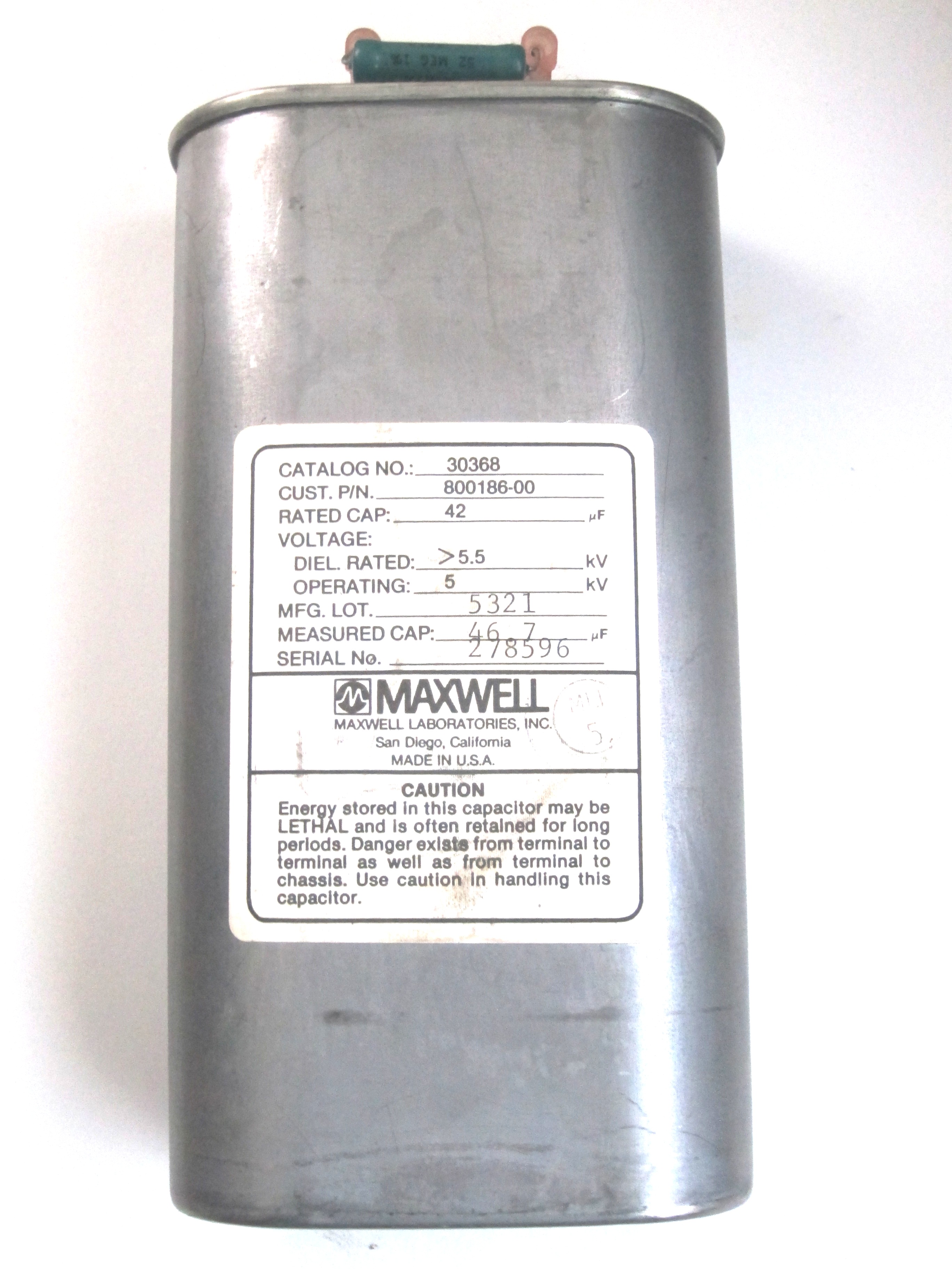
Fig. 36.4
A high-energy capacitor used on a cardiac defibrillator. The capacitor is rated 42 microfarad at 5000 volts. Using the formula E = ½ C V2 the energy stored in the capacitor becomes = ½ (42 × 10−6)(50002) = 525 J (Reprinted under the Creative Commons CC0 1.0 Universal Public Domain Dedication ► https://upload.wikimedia.org/wikipedia/commons/3/34/High-energy_capacitor_from_a_defibrillator_42_MFD_%40_5000_VDC.jpg)
Note that the energy delivered during an initial monophasic defibrillation is usually 200 J, with less energy typically used for biphasic defibrillation.
36.2 Electrical Shock Hazards
Stimulation with electricity can cause muscle cells to contract, and can thus be used therapeutically in equipment such as pacemakers or defibrillators or diagnostically when a nerve stimulator is used to assess the degree of neuromuscular blockade. However, contact with a large electrical voltage (such as a power line), whether AC or DC, can lead to injury or even death, often as a result of ventricular fibrillation. It takes approximately 3 times as much DC current as AC current to cause ventricular fibrillation.
◘ Figure 36.5 illustrates a typical AC electrical power arrangement in schematic form. A typical electrical outlet consists of 2 wires (“hot” and “neutral”) in conjunction with a third “ground” connection (◘ Fig. 36.6). The wire designated as “hot” carries the current to the load while the other (“neutral”) wire returns the current to the source. The potential difference between the 2 is typically 110 and 120 volts. To receive an electrical shock, one must be in contact with the electrical circuit at 2 points, and there must be a voltage supply that causes current to flow through an individual (◘ Fig. 36.7).
Fig. 36.5
Schematic illustration of a typical AC electrical power arrangement (Reprinted with permission, Cleveland Clinic Center for Medical Art & Photography © 2017. All Rights Reserved)
Fig. 36.6
A typical electrical outlet consists of 2 wires (“hot” and “neutral”) in conjunction with a third “ground” connection. The wire designated as “hot” carries the current to the load while the other (“neutral”), returns the current to the source. The potential difference between the 2 is typically 110 to 120 volts (Reprinted with permission, Cleveland Clinic Center for Medical Art & Photography © 2017. All Rights Reserved)
Fig. 36.7
To receive an electrical shock, one must be in contact with an active electrical circuit at 2 points (Reprinted with permission, Cleveland Clinic Center for Medical Art & Photography © 2017. All Rights Reserved)
When an electrical shock occurs, damage can occur in 1 of 2 ways. In the first mechanism, the electrical current can disrupt the normal physiological function of cells. Depending on its magnitude and path, the current can contract muscles, paralyze respiration, or lead to cardiac arrest via ventricular fibrillation. The second mechanism involves the dissipation of electrical energy throughout the body’s tissues: An electrical current passing through any resistance raises the temperature of that substance, sometimes sufficiently to produce a burn. Basically, the electricity cooks the tissue it passes through.2 ◘ Table 36.1 summarizes the physiological effects of various currents passing through the body for a 1-second duration.
Table 36.1
Physiological effects of various degrees of electrical current
Electric Current (1 second contact) | Physiological effect |
|---|---|
20 μA | Can possibly cause ventricular fibrillation in a “microshock” setting |
1–5 mA | Threshold of feeling, tingling sensation. |
10–20 mA | “Can’t let go!” current – Onset of sustained muscular contraction. |
100–300 mA | Ventricular fibrillation in “macroshock” setting |
The severity of an electrical shock is determined by the amount of current (amperes), its path through the body, and the duration of the current flow. For the purposes of this discussion, it is helpful to divide electrical shocks into 2 categories. Macroshock refers to large amounts of current flowing through a person, which can cause harm or death. Microshock refers to very small amounts of current (in the microampere and milliampere range) and applies only to the electrically susceptible patient, such as an individual who has an external conduit that is in direct contact with the heart. This can be a pacing wire or a saline-filled catheter such as a central venous or pulmonary artery catheter. In the case of an electrically susceptible patient, even minute amounts of current (microshock) may cause ventricular fibrillation.
In the electrically susceptible patient, ventricular fibrillation can be produced by a current that is below the threshold of human perception. The exact amount of current necessary to cause ventricular fibrillation in this type of patient is unknown (the experiments would be unethical), but based on animal experiments is believed to be as little as 20 μA.
36.2.1 Grounding
Ground connections on electrical plugs are used to help prevent electric shocks. An electrical shock may occur when an individual gets connected between the hot and neutral connections in a circuit, either directly as shown in ◘ Fig. 36.7, or via a frayed wire that has resulted in a short circuit producing a “hot case,” as illustrated in ◘ Fig. 36.8.
Fig. 36.8
In the absence of an electrical grounding system, a frayed wire or other problem may result in a short circuit, producing a “hot case” that could electrocute anyone who touches it (Reprinted with permission, Cleveland Clinic Center for Medical Art & Photography © 2017. All Rights Reserved)
Note, however, that if a 3-pronged plug is employed so that the case is grounded, any short circuit current from a frayed wire or similar problem will safely return any current to the ground instead of travelling through the victim. This is illustrated in ◘ Fig. 36.9.
Fig. 36.9
When an electrical grounding system is used, any frayed wire that would ordinarily result in a short circuit and a “hot case” instead results in electricity passing through the ground wire rather than through anyone who might be in contact with the “hot case” (Reprinted with permission, Cleveland Clinic Center for Medical Art & Photography © 2017. All Rights Reserved)
36.2.2 The Line Isolation Monitor
Isolated power systems are frequently used in operarting rooms. Such systems use an isolation transformer system so that neither of the 2 output lines powering the operating room equipment offers any voltage with respect to ground (◘ Figs. 36.10, 36.11, and 36.12). This helps eliminate the shock hazard associated with working in wet environments such as the operating room.
Fig. 36.10
Isolated power systems are frequently used in operating rooms. Such systems use an isolation transformer system so that neither of the 2 output lines powering the operating room equipment offers any voltage with respect to ground (Reprinted with permission, Cleveland Clinic Center for Medical Art & Photography © 2017. All Rights Reserved)
Fig. 36.11


When an isolated electrical power systems is used, since neither of the 2 output lines offers any voltage difference with respect to ground, no shock hazard is offered to anyone who comes into contact with either one of the 2 outputs of the isolation transformer (Reprinted with permission, Cleveland Clinic Center for Medical Art & Photography © 2017. All Rights Reserved)
Related posts:


Stay updated, free articles. Join our Telegram channel
Full access? Get Clinical Tree
