CHAPTER 56
Tendon Injections
INDICATIONS
• The indications for tendon or ligament injections can fall into 1 of 2 categories: diagnostic and therapeutic. Infiltration of local anesthetic along the tendon sheath can confirm the suspected diagnosis through symptom relief. Indications for therapeutic injections include decreased mobility and range of motion, pain, and the need to place medication in the area of pathology as a therapeutic adjunct to other forms of treatment.
• Common tendon/soft tissue–related conditions for which diagnostic and therapeutic injections are indicated:
![]() Bursitis
Bursitis
![]() Ischial
Ischial
![]() Trochanteric
Trochanteric
![]() Pes anserine
Pes anserine
![]() Patellar
Patellar
![]() Tendinopathy/tendonosis
Tendinopathy/tendonosis
![]() Bicipital tendonitis
Bicipital tendonitis
![]() Supraspinatus tendonitis
Supraspinatus tendonitis
![]() De Quervain tenosynovitis
De Quervain tenosynovitis
![]() Patellar tendonitis
Patellar tendonitis
![]() Achilles tendonitis
Achilles tendonitis
![]() Medial/lateral epicondylitis
Medial/lateral epicondylitis
![]() Levator scapulae tendonitis
Levator scapulae tendonitis
![]() Enthesopathy
Enthesopathy
![]() Iliolumbar ligament
Iliolumbar ligament
![]() Sacrococcygeal ligament
Sacrococcygeal ligament
![]() Sacrotuberous ligament
Sacrotuberous ligament
![]() Sacrospinous ligament
Sacrospinous ligament
![]() Sacroiliac ligament
Sacroiliac ligament
![]() Interspinous ligament
Interspinous ligament
![]() Supraspinous ligament
Supraspinous ligament
![]() Neuromas/ganglion cysts
Neuromas/ganglion cysts
![]() Fasciitis
Fasciitis
![]() Plantar fasciitis
Plantar fasciitis
![]() Entrapment syndromes
Entrapment syndromes
CONTRAINDICATIONS
• Relative contraindications
![]() Needle phobia
Needle phobia
![]() Underlying coagulopathy/bleeding diathesis
Underlying coagulopathy/bleeding diathesis
![]() Failure to respond to two previous injections
Failure to respond to two previous injections
![]() Anticoagulation therapy
Anticoagulation therapy
![]() Uncontrolled diabetes mellitus
Uncontrolled diabetes mellitus
![]() Pregnancy
Pregnancy
• Absolute contraindications
![]() Local cellulitis
Local cellulitis
![]() Acute fracture
Acute fracture
![]() Septic arthritis
Septic arthritis
![]() Bacteremia
Bacteremia
![]() History of allergy or anaphylaxis to injectate
History of allergy or anaphylaxis to injectate
![]() Local tumor
Local tumor
![]() Inability of patient to understand consent
Inability of patient to understand consent
RELEVANT ANATOMY
Bicipital Tendonitis/Tendonosis
• The long head originates at the greater tuberosity of the humerus, glenoid labrum, and supraglenoid tubercle (Figure 56-1).1
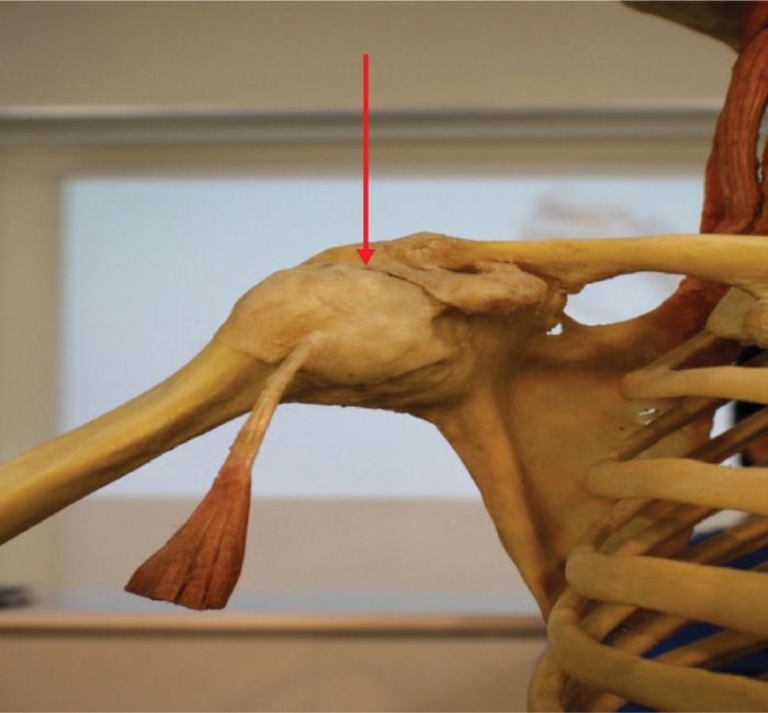
Figure 56-1. Anatomical depiction of the long head of the biceps inserting onto the greater tuberosity of the humerus (arrow).
• The short head originates at the coracoid process. These sites are common areas of inflammation in bicipital tendonitis.
• Arterial supply via the circumflex humeral artery1
• Most commonly the long head of the biceps becomes inflamed where it passes through the bicipital groove.
![]() The tendon may become impinged between the head of the humerus, acromion, and coracoclavicular ligaments with elevation and internal rotation of the arm.
The tendon may become impinged between the head of the humerus, acromion, and coracoclavicular ligaments with elevation and internal rotation of the arm.
• Distal inflammation along the insertional site is less common.
• The musculocutaneous nerve (C5C6) provides innervation to the biceps muscle.
Clinical Anatomy
• Point tenderness in the bicipital groove
• Anterior shoulder pain with referral to the arm
• Positive Yergason test—anterior shoulder pain with flexion of elbow to 90 degrees and resisted supination of the wrist
Levator Scapula
• Originates at the lateral mass of C1-C4 and the tendon inserts on the superior medial angle of the scapula (Figure 56-2)
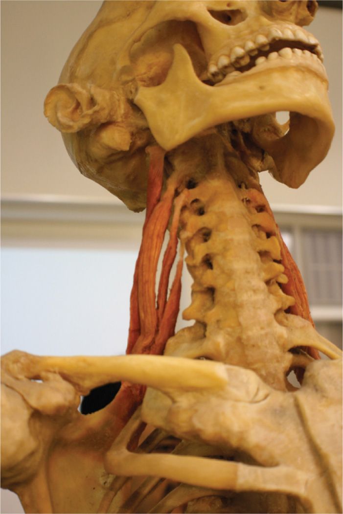
Figure 56-2. Anatomical depiction of the levator scapula originating at the lateral masses of C1-C4 and inserting on the superior medial angle of the scapula.
• Motor innervation by dorsal scapular nerve (C5)
Clinical Anatomy
• Pain along the superior medial angle of the scapula
• Painful, stiff neck
• Limited cervical rotation
• Pain at the angle of the neck, where the levator emerges from beneath the anterior border of the upper trapezius muscle
Lateral Epicondylosis/Epicondylitis
• Wrist extensors and supinators attach to the humerus at the lateral epicondyle
• These muscles pass laterally over the radiocapitellar joint
Clinical Anatomy
• Inflammation and enthesopathy occur with repetitive motion (Figure 56-3)—carpenters, typists, tennis players (especially backhand)
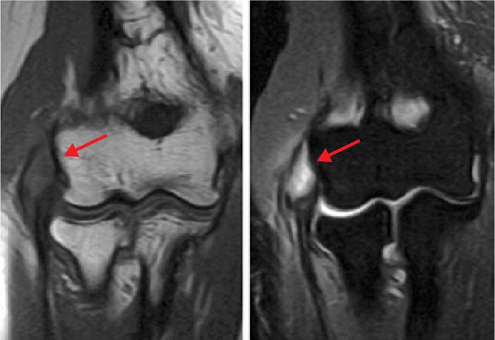
Figure 56-3. MRI images of lateral epicondyle (T1 on the left and T2 on the right).
• “Coffee cup sign”—pain worse when holding a coffee cup or thick phone book, turning a door knob
• Pain worse with resistive extension
Supraspinous/Interspinous Ligaments
• The supraspinous and interspinous ligaments course from spinous process to spinous process (Figure 56-4).
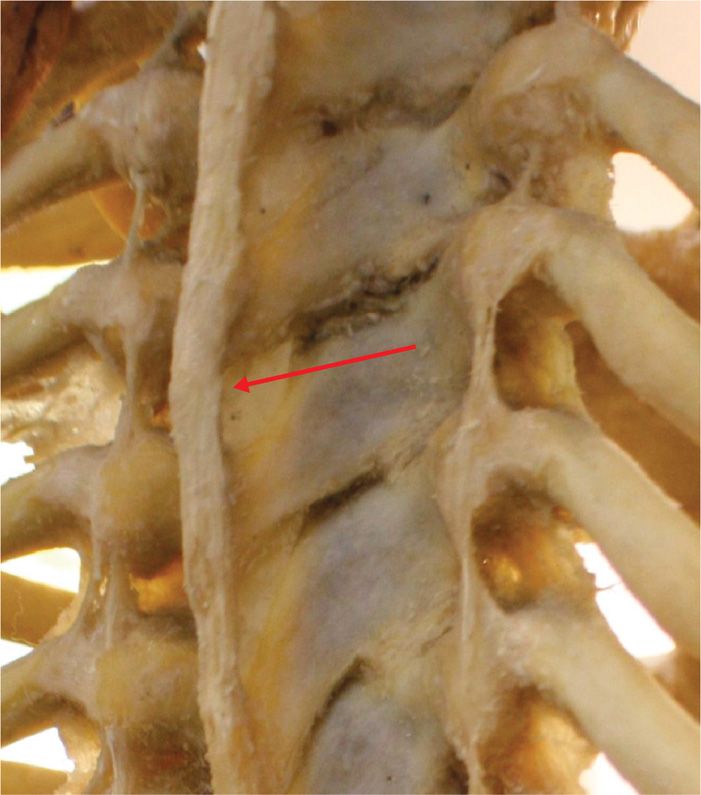
Figure 56-4. Supraspinous and interspinous ligaments.
• The supraspinous ligament is found from C7-L3 as opposed to the interspinous ligament which courses the entire length of the spine.2
• Protects against spinal separation and flexion.
• Innervated by the medial dorsal primary rami.
Clinical Anatomy
• Afferent nociceptors are activated by tearing or micro-tears in the ligament, typical of deceleration or acute flexion-extension injuries resulting in midline spine pain.
• Micro-tearing can lead to ligamentous laxity over time, which promotes poor posture and mechanical derangement of the spine with ensuing chronic spine pain (Figure 56-5).
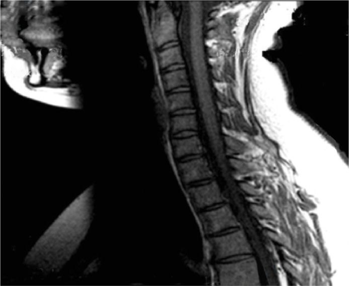
Figure 56-5. Interspinous/supraspinous ligamentous laxity depicted by the arrow from C7-T3.
Distal Piriformis
• Originates at the anterior surface of the inferior lateral angle of the sacrum.
• Inserts on the medial side of the superior surface of the greater trochanter (Figure 56-6).3
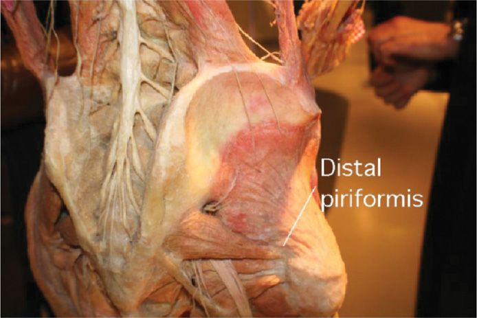
Figure 56-6. Distal piriformis tendon depicted inserting onto the greater trochanter.
• In 20% of patients, all or part of the sciatic nerve passes through the piriformis muscle.3
• Innervated by the piriformis nerve (L5, S1, S2).
Clinical Anatomy
• Lateral thigh pain
• Buttock pain
• Pain with paresthesia can be noted in the posterior thigh, and hip with radiation into the distal leg and foot
• Point tenderness along the posterior superior greater trochanter
• Symptoms aggravated by prolonged sitting and with a combination of hip flexion, adduction, and medial rotation
Iliolumbar Ligament
• The iliolumbar ligament originates from the L-5 transverse and is made up of an anterior and posterior band (Figure 56-7).
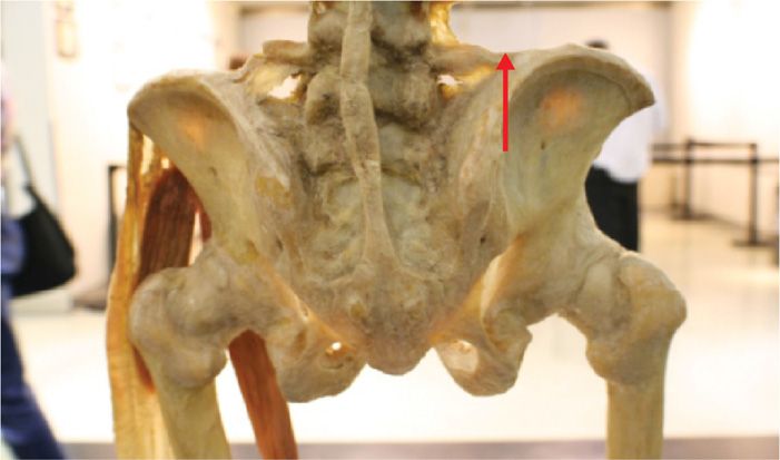
Figure 56-7. Iliolumbar ligament originating at L5 transverse process and inserting on the iliac crest.
• The anterior band is broad and flat and has two different anatomic varieties.
![]() Type 1 originates from the anterior aspect of the inferiolateral portion of the L-5 transverse process and fans out widely before inserting on the anterior portion of the iliac tuberosity.
Type 1 originates from the anterior aspect of the inferiolateral portion of the L-5 transverse process and fans out widely before inserting on the anterior portion of the iliac tuberosity.
![]() Type 2 originates anteriorly, laterally, and posteriorly from inferiolateral aspect of the L-5 transverse process and fans out before inserting on the anterior portion of the iliac tuberosity.
Type 2 originates anteriorly, laterally, and posteriorly from inferiolateral aspect of the L-5 transverse process and fans out before inserting on the anterior portion of the iliac tuberosity.
• The posterior band of the iliolumbar ligament originates from the apex of the L-5 transverse process and becomes fusiform just prior to inserting on the anterior margin and apex of the iliac crest.4
Clinical Anatomy
• Unilateral or bilateral low back pain
• Exquisite tender point at the posterior iliac crest (Figure 56-8)
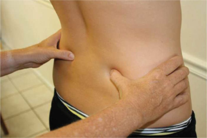
Figure 56-8. Exquisite tender point at the posterior iliac crest.
• Positive hip flexion test and Patrick maneuver
• Constant ache aggravated by prolonged sitting and standing—referral pain to the greater trochanter and into the groin (“my testicles are in a vice”)
PREOPERATIVE CONSIDERATIONS
• Informed consent and proper explanation of all potential complications.
• Anticoagulation/bleeding diathesis/thrombocytopenia.
• Physical examination of the target area for singes of infection, skin ulceration or necrosis, and extent of disease.
• Patient must be able to lie still for the intended length of the procedure.
• Consider intravenous access for IV fluid and medications for sedation or hypotension if there is concern for a vasovagal reaction.
• Evaluation for contrast allergy—this is of the utmost importance if using fluoroscopy, since the utilization of contrast will allow for precise needle placement. This is not a concern for ultrasound-guided injections.
FLUOROSCOPIC/ULTRASOUND VIEWS
• When using fluoroscopic guidance for supraspinous/interspinous, levator, iliolumbar and distal piriformis tendon/ligament injections, always start with anterior-posterior (AP) images to confirm your location and to line up the anatomical structures.
![]() Slight cephalad tilt with ipsilateral obliquity may enhance visualization of the superior medial portion of the greater trochanter for distal piriformis tendon injections (Figure 56-20A).
Slight cephalad tilt with ipsilateral obliquity may enhance visualization of the superior medial portion of the greater trochanter for distal piriformis tendon injections (Figure 56-20A).
![]() Cephalocaudal adjustments in the AP view should be done to square up the end plates and line up the spinous processes midline when performing supraspinous and interspinous ligament injections (Figure 56-17).
Cephalocaudal adjustments in the AP view should be done to square up the end plates and line up the spinous processes midline when performing supraspinous and interspinous ligament injections (Figure 56-17).
• Cephalad tilt with ipsilateral oblique can enhance visualization of the PSIS when performing an iliolumbar ligament injection (Figure 56-19A).
• Lateral views should always be done to verify depth (Figure 56-18B).
EQUIPMENT
• 22- or 25-gauge 1.5- to 3.5-in spinal needle
• 30-gauge subcutaneous needle
• 5 cc syringe for local anesthetic/deposteroid
• 3 cc syringe for contrast
• Extension tubing
MEDICATIONS
• 0.5% bupivacaine
• 1% lidocaine
• Deposteroid
• Nonionic contrast (Omnipaque 240 or Isovue 300)
• Prep solution
INTRAOPERATIVE TECHNICAL STEPS
Bicipital Tendon Injection
• The tendon is palpated in the bicipital groove of the humerus.
• After a sterile prep and subcutaneous local anesthetic infiltration, a 25-gauge 1.5- or 2-in needle is inserted into the skin over the area of maximum tenderness and directed into the groove at an angle near parallel to the groove itself.
• The goal is to enter the sheath of the biceps tendon and not the tendon itself (Figure 56-9).
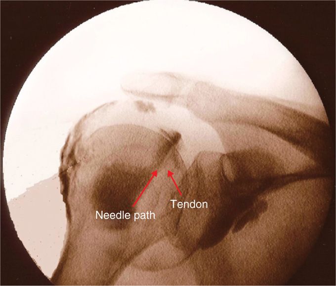
Figure 56-9. Bicipital tendon injection (fluoroscopy).
• Increased resistance to injection indicates intra-tendinous placement and the needle should be withdrawn slightly until there is very little resistance to injection.5
• After negative aspiration and no resistance, 2 to 3 cc of 0.5% bupivacaine with deposteroid is injected slowly
Zhang et al describe an ultrasound-guided approach.6
• The patient is positioned supine with the torso and upper body and the ipsilateral arm alongside the body with the elbow flexed 90 degrees.
• The skin surrounding the needle entry point is cleaned with Betadine solution and sterile drapes placed.
• The ultrasound transducer is protected with a sterile cover containing a small amount of gel.
• A preliminary ultrasound evaluation is performed with an ultrasound unit with multi-frequency linear transducers.
![]() The transducer frequency is chosen based on the depth of the individual anatomic structure.
The transducer frequency is chosen based on the depth of the individual anatomic structure.
• Color Doppler is used to identify local vascular structures.
• On the transverse scanning of proximal humerus, the brachial bicipital groove and the biceps brachii tendon can be seen clearly (Figure 56-10A). The tendon appears as an echogenic ellipse within the groove.
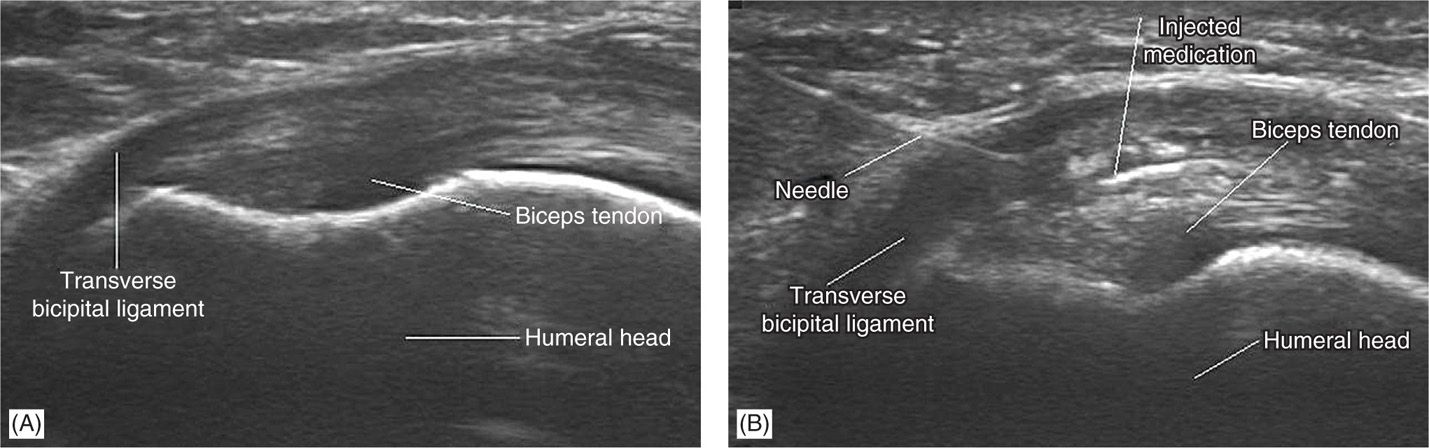
Figure 56-10. (A) Transverse ultrasonogram at the level of brachial bicipital groove shows the biceps brachii tendon in the groove and the tendon appearing as an echogenic ellipse within the groove. (B) Transverse ultrasonogram of the biceps brachii tendon at the level of the brachial bicipital groove after injection of medication (corticosteroid and lidocaine). Note the distention of the peritendon sheath space and circumferential spread of medication around the tendon. (Both the images were reproduced with permission from Zhang et al. Ultrasound guided injection for the biceps brachii tendinitis: Results and Experience. Ultrasound in Med. & Biol., Vol. 37, No. 5, pp. 729–733, 2011.)
• A lateral to medial approach using a 25-gauge, 1.5-in needle is performed. The needle is visualized in the long axis of the probe and advanced under ultrasound guidance.
• Once the needle tip is seen within the brachial bicipital groove, the corticosteroid is delivered under real-time monitoring (Figure 56-10B).
Levator Scapula Tendon Injection
• The patient is positioned seated, if no fluoroscopy is being used, or prone if using fluoroscopy.
• The tendon insertion site is marked over the superior angle of the scapula and the area of max tenderness is identified (Figure 56-11).
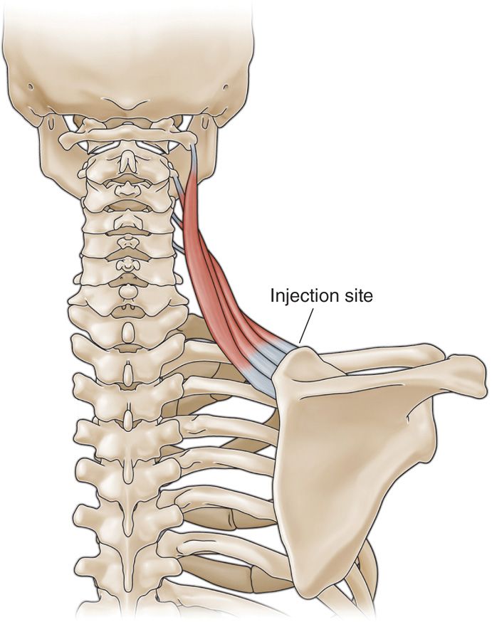
Figure 56-11. Levator injection site.
• After sterile prep, the skin is infiltrated with 1% lidocaine; then a 25-gauge 1.5-in spinal needle is inserted under fluoroscopic guidance using a coaxial technique.
• The needle is advanced until it contacts bone along the superior angle of the scapula (Figure 56-12).
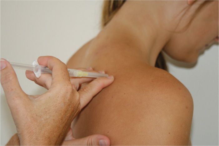
Figure 56-12. Levator scapula injection without fluoroscopy.
• Then, the needle is walked off the bone until it is seated in the tendon sheath.
• After negative aspiration, 1cc of contrast is injected to ensure proper placement and no vascularization.
• Then, 3 cc of 0.5% bupivacaine with deposteroid is injected.
• Laying an RF probe across the enthesopathy may denervate the periosteum, giving pain relief (Figure 56-13).
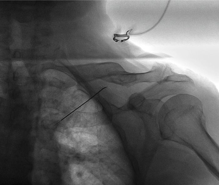
Figure 56-13. Radiofrequency lesion, right levator.
Lateral Epicondyle Injection
• For the nonfluoroscopic injection, the elbow is held in the noninjecting hand, and the lateral epicondyle identified by palpation (Figure 56-14).
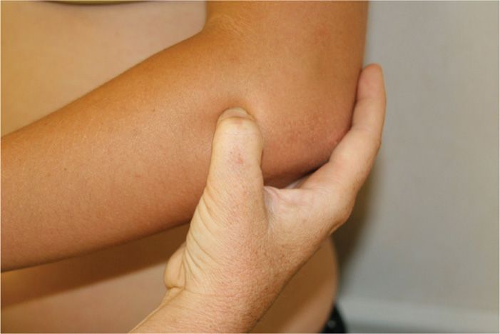
Figure 56-14. Lateral epicondyle examination.
• Fluoroscopically, the radial head is identified (Figure 56-15).
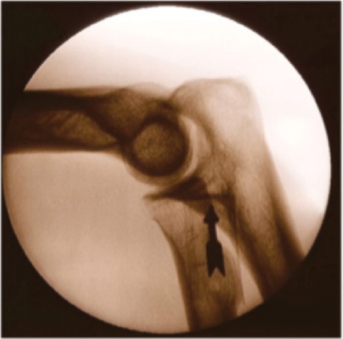
Figure 56-15. Fluoroscopic location of lateral epicondyle.
• The radial nerve lies medial to the tendon, so the injection needs to be kept laterally.
• The injection is placed at the base of the tendon attachment (Figure 56-16).
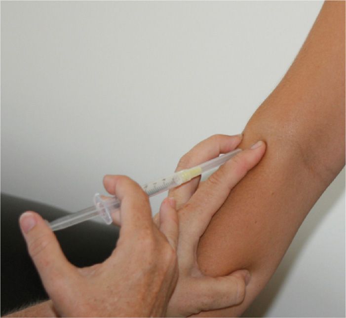
Figure 56-16. Lateral epicondyle injection.
Supraspinous/Interspinous Ligament Injection
• The patient is placed prone.
• After sterile preparation and drape, the spinal interspace of interest (the area of tenderness) is located by fluoroscopy (Figure 56-17).
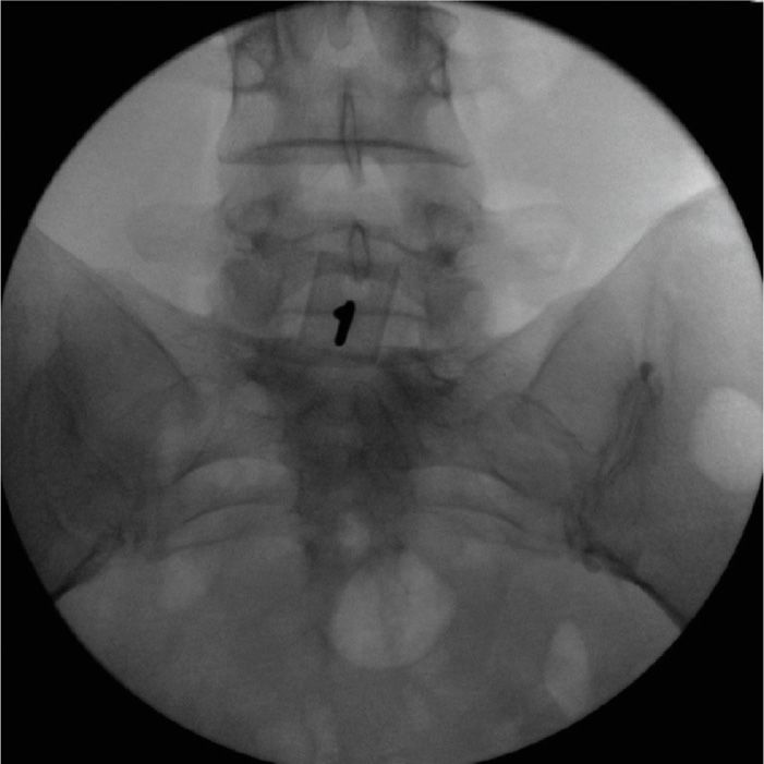
Figure 56-17. Midline tenderness at L5S1.
• Local anesthesia of the skin and subcutaneous tissues is performed with 1% lidocaine.
• Then, a 22-gauge spinal needle is advanced under fluoroscopic guidance between the affected spinous processes so that the tip of the needle is placed directly between the affected spinous processes on the PA image (Figure 56-18A).7
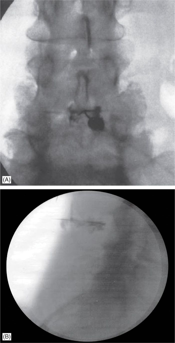
Figure 56-18. (A) PA view of interspinous injection. (B) Contrast infiltrating the space between the L3 and L4 spinous processes. (Both the images were reproduced with permission from Lamer et al. Fluoroscopically-Guided Injections to Treat “Kissing Spine” Disease. Pain Physician: July/August 2008:11:549-554.)
• Lateral views are then taken to verify that the needle is placed midway along the dorsal-ventral axis of the processes.7
• Then, after negative aspiration, 1 cc of contrast is injected to reveal contrast spread between the targeted spinous processes (Figure 56-18B).7
• This is followed by the injection of 2 cc of 0.5% bupivacaine and deposteroid.
Iliolumbar Ligament Injection
• The patient is placed prone.
• The target site of injection is the posterior iliac crest identified by fluoroscopy (Figure 56-19A).
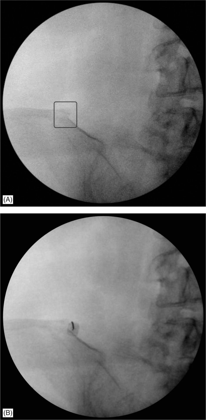
Figure 56-19. (A) Bone spur seen on fluoroscopy at the iliolumbar ligament insertion site. (B) Final needle placement at the iliolumbar ligament insertion site.
• After sterile prep and drape, the skin and subcutaneous tissues are infiltrated with 1% lidocaine.
• Then a 22- or 25-gauge 3.5-in spinal needle is inserted under fluoroscopic guidance using a coaxial technique.
• The needle is advanced under fluoroscopic guidance until it contacts bone along the posterior iliac crest (Figure 56-19B).
• The needle is then walked of the bone medially until it is seated in the tendon sheath.
• After negative aspiration, 1 cc of contrast is injected to reveal contrast spread along the tendon and to ensure proper placement without vascularization.
• Then, 2 cc of 0.5% bupivacaine with deposteroid is injected.
Distal Piriformis
• Patient is placed prone.
• AP views of the lumbosacral junction and hip of the target side are visualized. Slight cephalad tilt with ipsilateral obliquity will help enhance visualization of the target at the medial superior portion of the greater trochanter (Figure 56-20A).
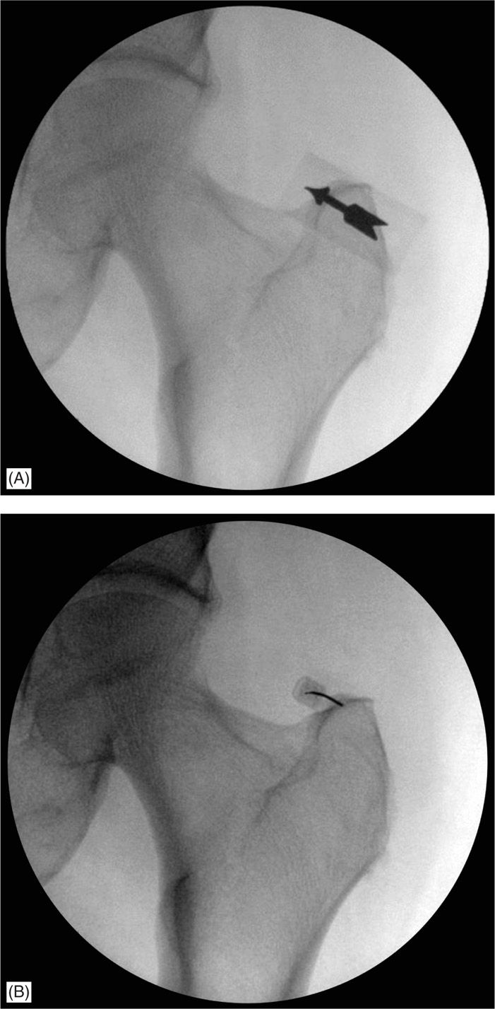
Figure 56-20. (A) Fluoroscopic view depicting the needle target along the distal piriformis tendon insertion on the greater trochanter. (B) Final needle placement at the distal piriformis insertion site.
• After sterile prep and drape, the skin and subcutaneous tissues are infiltrated with 1% lidocaine.
• Then a 22 or 25 gauge 3.5 inch spinal needle is inserted under fluoroscopic guidance using a coaxial technique (Figure 56-20B).
• The needle is advanced under fluoroscopic guidance until it contacts bone along the medial superior portion of the greater trochanter.
• The needle is then walked of the bone medially until it is seated in the tendon sheath.
• After negative aspiration, 1 cc of contrast is injected to reveal contrast spread along the tendon and to ensure proper placement without vascularization.
• Then, 3 cc of 0.5% bupivacaine with deposteroid is injected.
POSTPROCEDURE CONSIDERATIONS
• The patient should be followed up by telephone next day for the potential complications and immediate pain relief secondary to local anesthetic. The anti-inflammatory effect of steroid will not be apparent until 1 or 2 weeks. Patient should be advised to call pain service for any procedure related complications and/or any unexpected neurological deficit. Patient should be monitored closely for the following:
![]() Weakness
Weakness
![]() Swelling
Swelling
![]() Fever
Fever
![]() Bleeding
Bleeding
![]() Numbness
Numbness
![]() Exacerbation of symptoms
Exacerbation of symptoms
POTENTIAL COMPLICATIONS AND PITFALLS
• The overall incidence of side effects after local corticosteroid injection for tendon lesions is unknown.5
• Tendon rupture
• Exacerbation of pain
• Infection
• Nerve damage
• Weakness
• Numbness
• Damage to the tendon itself
• Allergic reaction to the injectate
• Tissue atrophy
CLINICAL PEARLS
• As early as 1930, Leriche pointed out that, after infiltration of a tender ligament or tendon with procaine, there was not just temporary relief of discomfort but a more prolonged effect than what one would expect from the anesthesia.8
• Corticosteroid injections are one of the most commonly used treatments for chronic tendon lesions.
• Despite their popularity, the evidence for long-term effectiveness is lacking.5
![]() Many of the studies have had inadequate design.
Many of the studies have had inadequate design.
![]() Problems include small sample sizes, unsuitable outcome measures, short term follow up, inadequate blinding, lack of a true placebo, and the inclusion of heterogeneous study populations.5
Problems include small sample sizes, unsuitable outcome measures, short term follow up, inadequate blinding, lack of a true placebo, and the inclusion of heterogeneous study populations.5
• Tendinitis may be inflammatory, but the primary problem is often degeneration with attempted repair, ie, tendinopathy or tendinosis rather than true tendinitis.9
Related posts:


Stay updated, free articles. Join our Telegram channel

Full access? Get Clinical Tree


