CHAPTER 25
Dorsal Root Ganglion Blocks and Radiofrequency Procedures
INTRODUCTION
• The dorsal root ganglion (DRG) contains the cell bodies of first-order sensory neurons, each of which project an axon from a peripheral receptor, and centrally to the posterior horn of the spinal cord, where they synapse with second-order neurons.
• There is one DRG for each spinal nerve root supplying the posterior aspect of the head, the trunk and the extremities; in the face, this function is carried out by the trigeminal ganglion.
• Unless prevented or treated, injury to the DRG often leads to the development of a chronic neuropathic pain state. Injection procedures that target the DRG could be used in the treatment of any radicular pain syndrome, such as primary radicular irritation, postherpetic neuralgia.
INDICATIONS
• Neuropathic pain resulting from injury to the DRG neurons, by infection, mechanical trauma, or inflammation resulting in the development of persistent low-threshold spontaneous firing of the neurons.
• The C2 nerve root is implicated in the production of occipital neuralgia, which may be more properly referred to as a C2 radicular pain syndrome. Block at the DRG, particularly with cold-pulsed RF, may be an effective treatment.
• Similarly, at all spinal levels neuropathic radicular pain may be diagnosed by selective local anesthetic blockade of the relevant nerve root, and potentially modulated by application of cold-pulsed RF energy.
ISSUES COMMON TO DRG BLOCKS AT ALL LEVELS
General Concerns
• RF blockade of the DRG carries the same risks as any procedure that accesses the neural foramen.
• These include inadvertent injury to nerves (the spinal root, DRG, and the spinal cord at relevant levels), vascular injury (to the spinal arteries at thoracic and lumbar levels, and the vertebral arteries at cervical levels).
• Infection, and hematoma.
• At cervical and thoracic levels, there is the additional risk of pneumothorax.
Neurolytic techniques directed at the DRG, including thermal radiofrequency and chemical lysis, carry a greater risk of producing deafferentation pain, and are hard to control. Pulsed dose (low-temperature) radiofrequency treatment of the DRG is a much safer technique.
Contraindications to Injection
• Infection
• Uncorrected coagulopathy
• Anatomic variation that limits safe visualization of the DRG
• Lack of consent
Preoperative Considerations
• Preoperative consultation with the patient including history, a review of diagnostic studies, and physical examination is the standard of care.
• Physical examination should include heart, lungs, and airway; the proposed injection site; as well as a relevant neurologic and spinal examination.
• Review of medications should pay particular attention to anticoagulants, which should be discontinued with sufficient time to allow for normalization of clotting.
• Review of the history of allergic reactions, with particular attention to iodinated contrast sensitivity. Use of contrast is critical to placement of the needle adjacent to the DRG, and in patients with a contrast allergy pretreatment will be necessary to reduce this risk.
• Assessment of patient anxiety and pain level is important to allow for the selection of an appropriate sedation technique.
• Blocks of the DRG require nerve stimulation and therefore patient communication during the procedure is important.
• Sedation must be performed in such a way as to ensure that the patient is both comfortable and conscious.
• Informed consent is the standard of care.
• Physicians undertaking this procedure are assumed to be adequately trained in regional anesthesia, pain medicine, and resuscitation techniques. They must be proficient at routine spinal injection procedures before applying these (more advanced) techniques.
Equipment
• 27-gauge 1.5-in needle (for local anesthetic administration)
• 3 cc syringe (for local anesthetic administration)
• 5 cc syringe (for contrast administration)
• Low-volume extension tubing
• Radiofrequency cannulae
![]() 22-gauge 5-cm needle, 0.5 cm active tip for cervical levels
22-gauge 5-cm needle, 0.5 cm active tip for cervical levels
![]() 22-gauge 10- to 15-cm needle, 0.5 cm active tip for thoracic and lumbar levels (curved and straight should be available)
22-gauge 10- to 15-cm needle, 0.5 cm active tip for thoracic and lumbar levels (curved and straight should be available)
• Intravenous access supplies
• Resuscitation equipments and supplies standard to any anesthetizing location
Medications
• 1% lidocaine for cervical levels (to minimize the risk of vertebral artery uptake and seizure)
• 2% lidocaine for lumbar and thoracic levels
• Omnipaque 180 (a nonionic water-soluble iodine contrast solution)
LEVEL-SPECIFIC ISSUES FOR DRG BLOCKS
Cervical DRG at C2
Relevant Anatomy
• At the level of C2, the DRG occupies a unique position midway between the arch of C1 and C2.
• The depth of the ganglion is approximately in the middle third of the overlying C12 articulation.
• The vertebral artery is in immediate proximity to the DRG and overlays the joint.
Fluoroscopic Views
• Patient is positioned in a supine position, head is turned away from the side to be blocked (Figure 25-1).
• The vertebral end plates are properly aligned on fluoroscopic view by adjustment of the craniocaudal angle (Figure 25-2).
• The degree of obliquity is then determined by live fluoroscopic imaging, such that the neural foramen is brought into sharp resolution.
• A near lateral view will be achieved in the upper cervical spine, and more operative space will be available than with a true lateral (Figure 25-3).
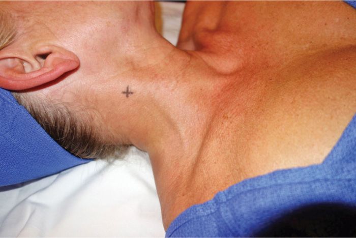
Figure 25-1. Patient position C2 DRG. For the high cervical approach (at C2), the patient is positioned supine, with the head rotated away from the foramen to be targeted. The fluoroscope is placed in a foraminal view, using an oblique and cranial tilt.
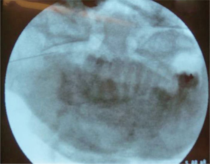
Figure 25-2. AP fluoroscopic view C2 DRG. The tip of the needle overlays the C1-C2 articulation, over the middle third of the joint.
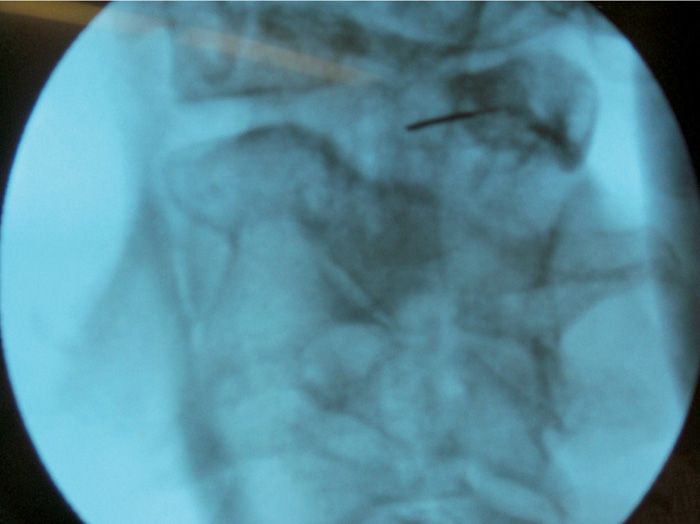
Figure 25-3. Lateral fluoroscopic view C2 DRG.
For patient comfort, or operator preference, this can also be achieved with the patient in a lateral position, provided the head is maintained in a stable and laterally neutral position, and an open mouth view (essential for assessing the medial progress of the needle) can be obtained.
Our Preferred Technique
• Localize the DRG in the cervical spine at C2 midway between the arch of C1 and C2, and overlying the C12 articulation.
• Determine the skin entry site using a straight needle coaxial with this point.
• The operator must be thoroughly familiar with the course of the vertebral artery, which overlays the joint, and is sometimes tortuous.
• As the needle nears the foramen, these relationships should also be confirmed in an open-mouth view.
• Next, using an AP image (again, squared craniocaudal with respect to the vertebral end plates at that level), the medial progression of the needle tip is observed.
• The final location of the needle tip should be approximately in the middle third of the overlying C12 articulation.
• 1 mL of omnipaque-180 contrast solution is then administered under live digital-subtraction fluoroscopy, and should demonstrate a neurogram of the adjacent spinal nerve. In the cervical spine, we use digital subtraction as our standard to demonstrate vascular uptake, possibly due to puncture of a vertebral artery.
• The final image is saved for documentation.
• Sensory stimulation is then performed at a frequency of 50 Hz, progressing in 0.1 V increments to a maximum of 1 V. Stimulation at approximately 0.5 V indicates that the DRG is in adequate proximity to the active tip of the needle, and within the electromagnetic field of the lesion.
• Motor stimulation is not necessary at the C2 level due to the lack of motor function of this nerve.
• The safest lesioning technique is pulsed-mode low-temperature radiofrequency. We use a setting of radiofrequency bursts of 20 ms, at a frequency of 2 Hz, for 120 seconds, and maintain a maximum temperature of no more than 42°C.
Cervical DRG Block at C3-C8
Relevant Anatomy
In the cervical spine, the DRG is located in the most dorsal and cephalad aspect of the foramen, immediately behind the middle-third of the overlying facet-joint (Figure 25-4).
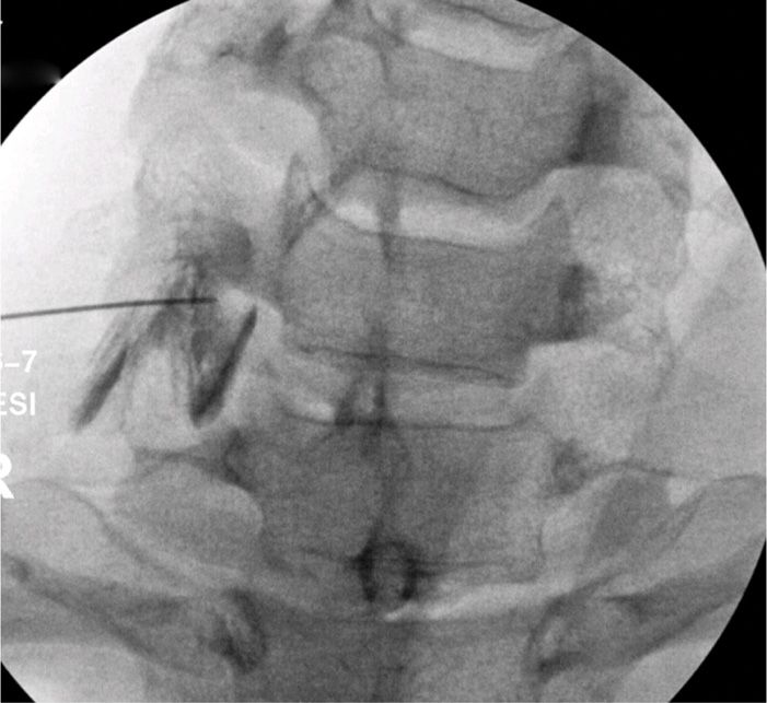
Figure 25-4. Patient position low cervical DRG. For the low cervical approach, the patient is positioned supine, with the head rotated away from the foramen to be targeted. The fluoroscope is placed in a foraminal view, using an oblique and cranial tilt.
Fluoroscopic Views
• In supine position, the patient’s head is turned away from the side to be blocked (Figure 25-5).
• The vertebral end plates are properly aligned on fluoroscopy by adjustment of the craniocaudal angle.
• The degree of obliquity is then determined by live fluoroscopic imaging, such that the neural foramen is brought into sharp resolution.
• A near lateral view will be achieved in the upper cervical spine, and more operative space will be available than with a true lateral.
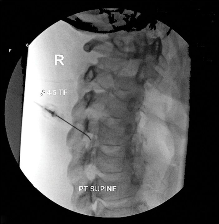
Figure 25-5. AP fluoroscopic view low cervical DRG. Needle position for the low cervical block should be approximately in the middle third of the overlying facet joint. The final position is determined by sensory stimulation of the appropriate root level.
In the event that the lower cervical levels are still inaccessible with this technique, a posterior approach with the patient prone in the manner of a thoracic foraminal access can also be used.
For patient comfort, or operator preference, this can also be achieved with the patient in a lateral position, provided the head is maintained in a stable and laterally neutral position.
Our Preferred Technique
• The location of the dorsal root ganglion in the cervical spine C3 through C8 is in the most dorsal and cephalad aspect of the foramen (Figure 25-6).
• Determination of the skin entry site using a straight needle must be coaxial with this point; however, care must be taken to avoid too oblique an angle, due to the presence of the adjacent lung in the low cervical levels.
• The operator must be thoroughly familiar with the course of the vertebral artery, which is relatively ventral with respect to the foramen, but is sometimes tortuous.
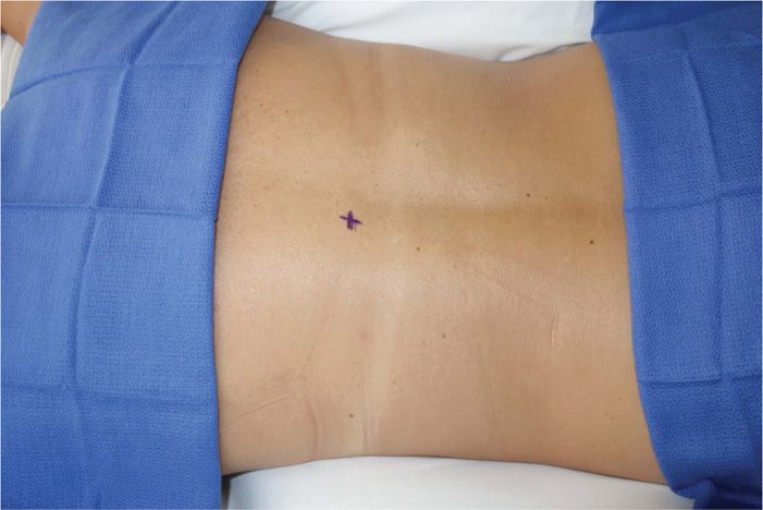
Figure 25-6. Oblique fluoroscopic view low cervical DRG.
As the needle nears the foramen, these relationships should also be confirmed in an oblique and lateral view.
• Next, using an AP image (again, squared craniocaudal with respect to the vertebral end plates at that level), the medial progression of the needle tip is observed.
• The final location of the needle tip should be approximately in the middle third of the overlying facet joint.
• 1 mL of omnipaque-180 contrast solution is then administered under live digital-subtraction fluoroscopy, and should demonstrate a neurogram of the adjacent spinal nerve. In the cervical spine, we use digital subtraction as our standard to demonstrate vascular uptake, possibly due to puncture of a vertebral artery.
• The final image is saved for documentation.
• Sensory stimulation is then performed at a frequency of 50 Hz, progressing in 0.1 V increments to a maximum of 1 V. Stimulation at approximately 0.5 V indicates that the DRG is in adequate proximity to the active tip of the needle, and within the electromagnetic field of the lesion.
• Motor stimulation is then performed at a frequency of 2 Hz, progressing in 0.1 V increments to a maximum of 3 V. Motor stimulation of the nearby root should occur at a much higher voltage than sensory stimulation, indicating that the electrode is adjacent to the sensory DRG, and relatively far from the ventral motor roots.
• The safest lesioning technique is pulsed-mode low-temperature radiofrequency. We use a setting of radiofrequency bursts of 20 ms, at a frequency of 2 Hz, for 120 seconds, and maintain a maximum temperature of no more than 42°C.
Thoracic DRG Block
Relevant Anatomy
In the thoracic spine, the DRG is located in the most dorsal and cephalad aspect of the foramen, immediately behind the middle third of the overlying facet joint.
Fluoroscopic Views
• With the patient in the prone position, the vertebral end plates are made square on fluoroscopy by adjustment of the craniocaudal angle (Figure 25-7).
• The degree of obliquity is then determined by live fluoroscopic imaging, such that the neural foramen is brought into sharp resolution.
• Experience is required to determine whether the oblique angle is becoming too large; thus increasing the risk of inadvertent pneumothorax.
• If the operator is uncomfortable with their ability to safely determine this angle, the procedure should be aborted, and consideration given to using CT guidance.
• While there is much greater radiation exposure with this technique, CT allows safe placement in the foramen, with direct visualization of the pleura.
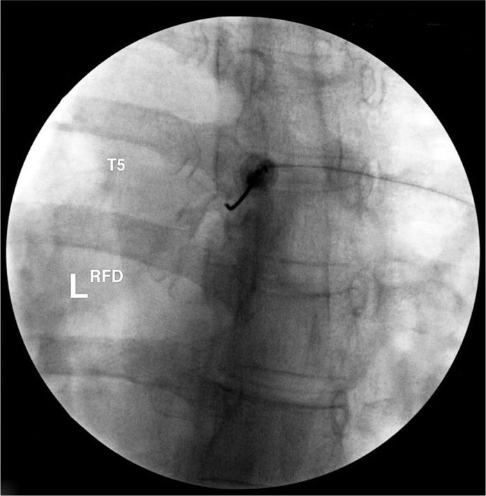
Figure 25-7. Patient position thoracic DRG. For the thoracic approach, the patient is positioned supine. The fluoroscope is placed in a foraminal view, using a minimally oblique and as needed cranial tilt.
Our Preferred Technique
• The location of the dorsal root ganglion in the thoracic spine is in the most dorsal and cephalad aspect of the foramen (Figure 25-8).
• Determination of the skin entry site using a straight needle must be coaxial with this point; however, care must be taken to avoid too oblique an angle, due to the presence of the adjacent lung. It is therefore advisable to use a curved tip needle in this circumstance.
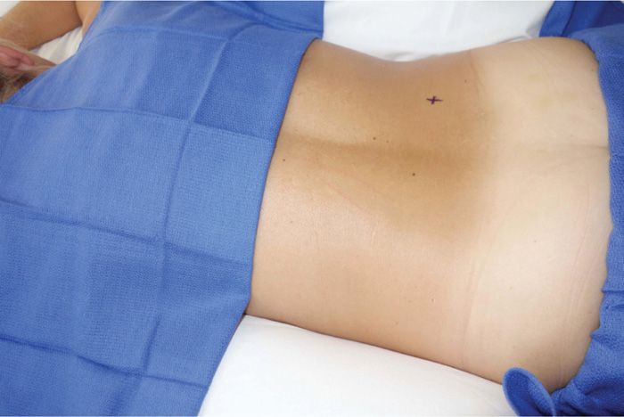
Figure 25-8. Oblique fluoroscopic view thoracic DRG. Needle position for the thoracic DRG should foraminal, using a curved needle, and only as oblique as is absolutely necessary, to avoid contact with the pleura and lung. The final position is determined by sensory stimulation of the appropriate root level.
As the needle nears the foramen, these relationships should also be confirmed in a lateral view.
• Next, using an AP image (again, squared craniocaudal with respect to the vertebral end plates at that level), the medial progression of the needle tip is observed. The final location of the needle tip should be approximately in the middle third of the overlying facet joint.
• 1 mL of omnipaque-180 contrast solution is then administered under live digital-subtraction fluoroscopy, and should demonstrate a neurogram of the adjacent spinal nerve. In the thoracic spine, we use digital subtraction as our standard to demonstrate vascular uptake, possibly due to puncture of a spinal artery. The final image is saved for documentation.
• Sensory stimulation is then performed at a frequency of 50 Hz, progressing in 0.1 V increments to a maximum of 1 V. Stimulation at approximately 0.5 V indicates that the DRG is in adequate proximity to the active tip of the needle, and within the electromagnetic field of the lesion.
• Motor stimulation is then performed at a frequency of 2 Hz, progressing in 0.1 V increments to a maximum of 3 V. Motor stimulation of the nearby root should occur at a much higher voltage than sensory stimulation, indicating that the electrode is adjacent to the sensory DRG, and relatively far from the ventral motor roots.
• The safest lesioning technique is pulsed-dose low-temperature radiofrequency. We use a setting of radiofrequency bursts of 20 ms, at a frequency of 2 Hz, for 120 seconds, and maintain a maximum temperature of no more than 42°C.
Lumbar DRG Block
Relevant Anatomy
In the lumbar spine, the DRG is located in the most dorsal and cephalad aspect of the foramen, immediately behind the middle third of the overlying facet joint.
Fluoroscopic Views
• With the patient in the prone position, the vertebral end plates are made square on fluoroscopy by adjustment of the craniocaudal angle (Figure 25-9).
• The degree of obliquity is then determined by live fluoroscopic imaging, such that the neural foramen is brought into sharp resolution.
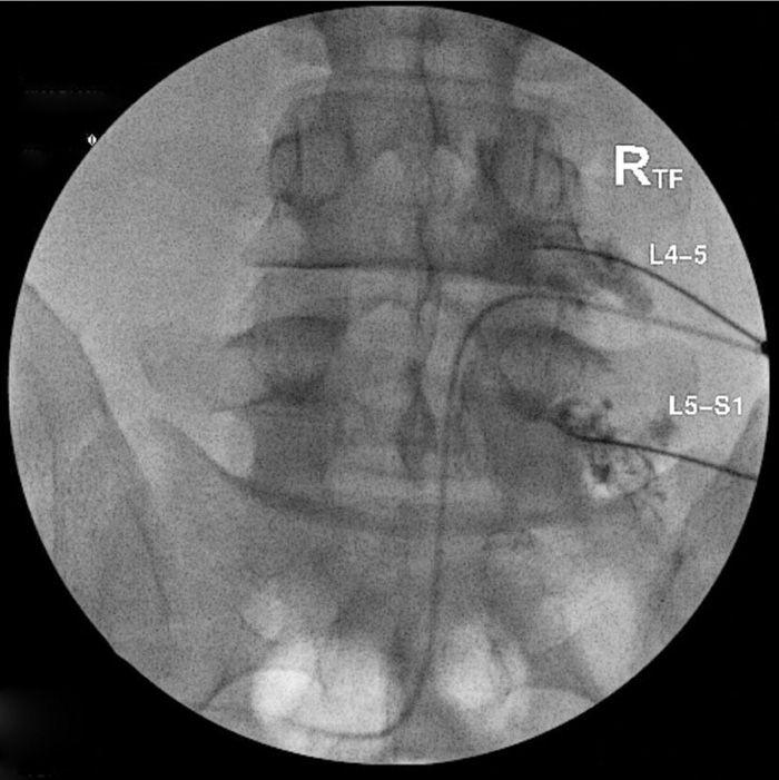
Figure 25-9. Patient position lumbar DRG. For the lumbar approach, the patient is positioned supine, with the head rotated away from the foramen to be targeted. The fluoroscope is placed in a foraminal view, using an oblique and cranial tilt.
Our Preferred Technique
• The location of the dorsal root ganglion in the lumbar spine is in the most dorsal and cephalad aspect of the foramen (Figure 25-10).
• Determination of the skin entry site using a straight needle must be coaxial with this point.
• As the needle nears the foramen, this relationship should also be confirmed in a lateral view.
• Next, using an AP image (again, squared craniocaudal with respect to the vertebral end plates at that level), the medial progression of the needle tip is observed.
• The final location of the needle tip should be approximately in the middle third of the overlying facet joint.
• 1 mL of omnipaque-180 contrast solution is then administered under live fluoroscopy, and should demonstrate a neurogram of the adjacent spinal nerve.
• The final image is saved for documentation.
• Sensory stimulation is then performed at a frequency of 50 Hz, progressing in 0.1 V increments to a maximum of 1 V. Stimulation at approximately 0.5 V indicates that the DRG is in adequate proximity to the active tip of the needle, and within the electromagnetic field of the lesion.
• Motor stimulation is then performed at a frequency of 2 Hz, progressing in 0.1 V increments to a maximum of 3 V. Motor stimulation of the nearby root should occur at a much higher voltage than sensory stimulation, indicating that the electrode is adjacent to the sensory DRG, and relatively far from the ventral motor roots.
• The safest lesioning technique is pulsed-dose low-temperature radiofrequency. We use a setting of radiofrequency bursts of 20 ms, at a frequency of 2 Hz, for 120 seconds, and maintain a maximum temperature of no more than 42°C.
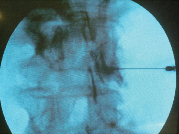
Figure 25-10. AP fluoroscopic lumbar DRG. Needle position for the lumbar DRG block should be foraminal. This can be achieved by entering the foramen using curved tip needle, and an oblique approach. Live contrast spread should be documented around the nerve root. The final position is determined by sensory stimulation of the appropriate root level.
CLINICAL PEARLS
• DRG injection using local anesthetic only can be diagnostic as well as therapeutic. Patients with a short-term positive response to a local anesthetic injection may be candidates for pulsed-dose radiofrequency (RF) ablation.
• The success of DRG blockade is entirely dependent on safely placing the needle adjacent to the ganglion, and away from the ventral motor root.
• The only way to confirm placement, is to sequentially demonstrate:
![]() By fluoroscopy—that the needle is in the most dorsal and cephalad portion of the foramen (except at the C2 level)
By fluoroscopy—that the needle is in the most dorsal and cephalad portion of the foramen (except at the C2 level)
![]() By contrast injection under live fluoroscopy—that the needle is adjacent to the DRG
By contrast injection under live fluoroscopy—that the needle is adjacent to the DRG
![]() By nerve stimulation—that the electrode is able to stimulate the sensory nerve at a much lower voltage than the motor nerve
By nerve stimulation—that the electrode is able to stimulate the sensory nerve at a much lower voltage than the motor nerve
Related posts:


Stay updated, free articles. Join our Telegram channel

Full access? Get Clinical Tree


