CHAPTER 71
Spinal Cord Stimulation: Implantation Techniques
INTRODUCTION
Electrical stimulation of neural structures is a widely used, nondestructive, reversible therapy, for chronic noncancer related pain. It has been evolving rapidly since the “gate theory,” developed by Melzack and Wall in 1965, which opened the door for this application. Neurostimulation may modulate pain pathways at the central nervous system and peripheral nervous system levels. Various techniques and technologies have been developed according to the site of stimulation: spinal cord stimulation (SCS), deep brain stimulation (DBS), motor cortex stimulation (MCS), large peripheral nerve stimulation (PNS), peripheral nerve field stimulation (PNFS), and more recently dorsal root ganglia stimulation (DRG-S). This chapter looks at percutaneous surgical techniques of electrical stimulation of the spinal cord.
INDICATIONS
Chronic neuropathic pain affects a significant percentage of the population and is often inadequately treated. It may result in low quality of life, medication overuse, and worsening of mood disorders. The FDA has approved SCS as an instrument in treatment of chronic intractable pain of the trunk and limbs including unilateral or bilateral pain associated with postlaminectomy syndrome, intractable low back pain and leg pain. Besides neuropathic, low back and limb pain there is evidence for off-label use of SCS for ischemic pain in refractory angina and peripheral vascular disease and some evidence for effectiveness in visceral pain. The indications of SCS are:
• Neuropathic pain in upper or lower extremities related to postlaminectomy syndrome (so-called failed back [neck] surgery syndrome—FBSS or FNSS)
• Complex regional pain syndrome (type I/II)
• Radiculopathy
• Plexopathy: traumatic (partial), postradiation
• Arachnoiditis
• Painful peripheral neuropathy including idiopathic small fiber neuropathy, metabolic (diabetic), infectious (HIV), and toxic (chemotherapy-induced) neuropathy
• Stump pain (postamputation)
• Ischemic pain associated with peripheral vascular disease
• Ischemic pain associated with refractory angina
• Visceral pain
• SCS indications associated with lower success rate
• Axial pain following spine surgery (back and neck)
• Postherpetic neuralgia pain
• Phantom pain
• Post-thoracotomy pain
• Incomplete spinal cord injury with complete or clinically distinguishable loss of posterior column function
• Central pain
As discerned, many of the poorer responsive conditions encompass deafferentation features of pain.
CONTRAINDICATIONS
• Any contraindication for regional anesthesia such as uncorrected coagulopathy or infection
• Pregnancy (though there are reports of uneventful pregnancies and deliveries on SCS)
• Severe central canal stenosis
• Neurologic deficit that would likely be amenable to surgery
• Significant/progressive spine instability
• Need for frequent follow up by magnetic resonance imaging as in multiple sclerosis
• Unacceptable surgical risk
• Cognitive impairment
• Implanted pacemaker or AICD (though off label use of SCS in this setting has been reported)
• Borderline personality disorder or other psychiatric co-morbidities that preclude success
• Previous lesion of dorsal root entry zone
Documentation for Off-Label Indications
Documentation for off-label use should include a detailed discussion with the patient. The physician may discuss representative original publications, review articles, book chapters, or technological review assessments, which detail the effectiveness and relative safety of SCS for the condition at hand.
A Statement of Medical Necessity
A letter documenting a statement of medical necessity should include the following components:
• Statement of request for SCS system.
• Short description of what the procedure entails including that neurostimulation is a nondestructive and reversible therapy.
• Detailed description of the medical decision making process (discussion of):
![]() Clinical symptoms
Clinical symptoms
![]() Imaging
Imaging
![]() Previous failed therapy—pharmacological, physical therapy, and interventional
Previous failed therapy—pharmacological, physical therapy, and interventional
![]() Pertinent selection criteria and how the patient fulfills those criteria
Pertinent selection criteria and how the patient fulfills those criteria
• Describe whether patient did undergo psychological evaluation.
• Detail the request for coverage in terms of trial, implant, professional fees, and facility fees. It should include also tentatively scheduled dates.
MECHANISM OF ACTION
The idea of electrical stimulation for pain control was based on the initial description of the “gate theory” by Melzack and Wall, whereby electrical stimulation of large myelinated Aβ (A beta) fibers in dorsal columns would result in closing the “gate” and obliterating onward central pain signal transmission from peripheral nociceptors (C fibers) (Figure 71-1). Applied electrical field in the epidural space affects various structures (dorsal columns, peripheral nerves, spinal tracts) and SCS mechanisms of action have been shown to be more complex than the “gate” theory. SCS mechanisms currently being researched involve:
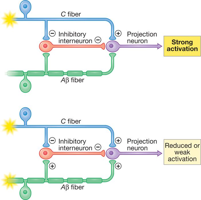
Figure 71-1. Spinal cord stimulation hypothesized “gate theory” mechanism. Stimulation of Aβ fibers closes the “gate” and results in reduced input and weak activation.
• Antidromic action potential spreading caudally in the dorsal columns to activate spinal segmental mechanisms
• Orthodromic ascending action potentials activating brainstem cells which could reinforce descending inhibition
• Direct inhibitory actions on central sensitization mechanisms
• Restoration and sustainability of blood flow (microcirculation) to the affected site by increasing the release of vasoactive mediators such as CGRP and SP
• Decreasing sympathetic output (important in sympathetically maintained pain) by antidromic effects
RELEVANT ANATOMY
The goal of spinal cord stimulation is to produce analgesia in the area of pain. Optimal pain relief is achieved when the paresthesia resulting from stimulation of dorsal column Aβ fibers overlaps the area of pain. An 80% overlap of paresthesia to area of pain has been empirically sought in SCS studies. To be able to accomplish this, the surgeon should understand:
• The structural and functional anatomy of spine
• The fluoroscopic anatomy of the spine
• Relevant clinical neurophysiology
• Limitations and capabilities of the equipment used
• Techniques to optimize parameters of stimulation to achieve better results
Epidural Space
• The epidural space is circumferential wrapping around the dura. It is bound by:
![]() The ligamentum flavum posteriorly
The ligamentum flavum posteriorly
![]() The posterior longitudinal ligament and vertebral bodies anteriorly
The posterior longitudinal ligament and vertebral bodies anteriorly
![]() The vertebral pedicles and intervertebral foramina with their penetrating nerve roots form the lateral borders
The vertebral pedicles and intervertebral foramina with their penetrating nerve roots form the lateral borders
• The posterior epidural space, dorsal to the dura, is the target of lead placement for SCS to facilitate dorsal column stimulation. This space is primarily occupied by fat tissue and small blood vessels, lymphatics and nerve roots laterally (Figure 71-2).
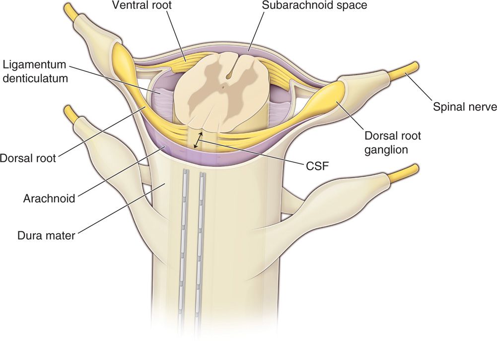
Figure 71-2. Percutaneous leads positioning in the epidural space. The posterior epidural space, dorsal to the dura, is the target of lead placement for spinal cord stimulation. This space is primarily occupied by fat tissue and small blood vessels, lymphatics and nerve roots laterally. Dorsal CSF (dCSF) fluid thickness along the spinal canal is the most important determinant of current spread.
• The diameter of the epidural space changes along the spinal column and should be taken into account when deciding the level entry into the epidural space. The greatest distance between the ligamentum flavum and the dura is found at the L2 in adults (5-6 mm), followed by thoracic spine (3-4 mm) and the least in the cervical spine region 1.5 to 2 mm.
Dorsal Columns
Dorsal columns are the target of electrical stimulation. They are formed by large-diameter, heavily myelinated, high conductance sensory fibers (Aβ) mediating tactile sensation and proprioception from the extremities and the trunk. Topographically they form the fasciculus gracilis and the fasciculus cuneatus collecting sensation from lower extremities and upper extremities, respectively. The lower extremities’ primary sensory afferent projections enter the spinal cord laterally in the lower segments and are positioned more medially and dorsally at the upper levels of the spinal cord as the trunk and upper extremity fibers enter the dorsal column tracts (Figure 71-3). Hence, the dorsal column’s fibers are somatotopically organized (Figure 71-3) in the following order from medial to lateral: sacral, lumbar, thoracic, and cervical. Smaller fibers are located more medially and conduct sensory information from more caudad segments. The nerve root fibers enter the spinal cord several levels higher than the corresponding vertebral entry point, as such, the leads should be placed accordingly.
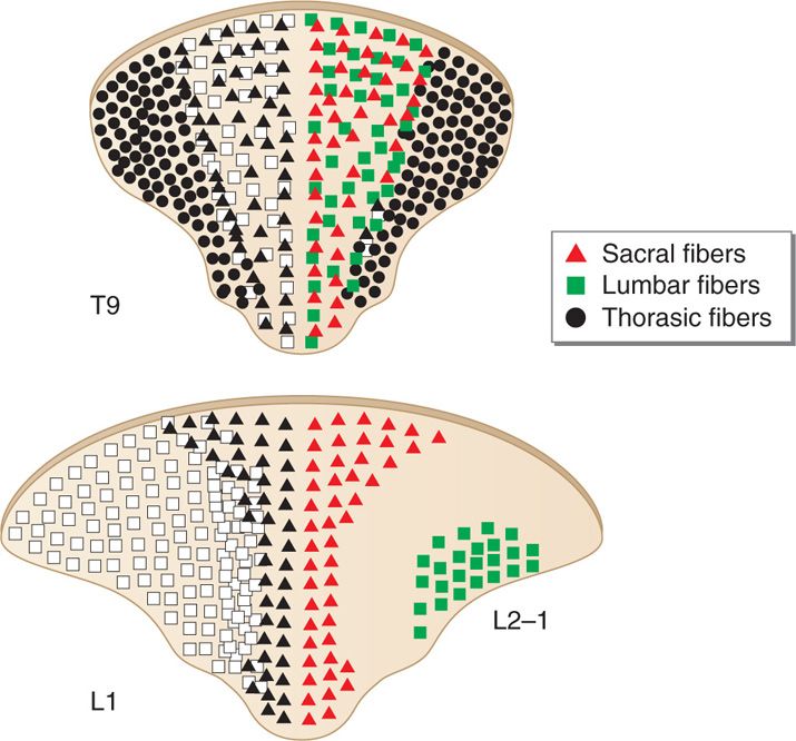
Figure 71-3. Topographical arrangement of dorsal columns of the spinal cord. The dorsal column’s fibers are somatotopically organized in the following order from medial to lateral: sacral, lumbar, thoracic, and cervical.
CSF Space
The most important factor determining stimulation parameters is the width of the high conductance CSF dorsal to the spinal cord (dCSF). Stimulation potentials will flow toward the path of least resistance (or higher conductance). The depth of dorsal CSF at various spinal levels and its relation to perception of paresthesia upon stimulation is displayed in Figure 71-4. A larger dCSF would result in lateral spread of the electrical field and stimulation of dorsal root entry zone nerve rootlets (Figure 71-5). These contain sensory fibers many of which are proprioceptive and involved in segmental motor reflexes. Their stimulation is thought to be responsible for the uncomfortable sensations (twitching and pain) experienced at the discomfort threshold.
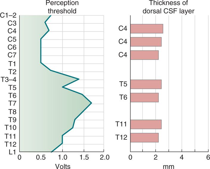
Figure 71-4. CSF fluid thickness along the spinal canal. Thickness of dorsal CSF fluid ranges from 2 to 6 mm along the spinal canal. Perception threshold (PT) is directly dependent on dCSF thickness. As noted, the greatest thickness occurs in the mid-thoracic spine.
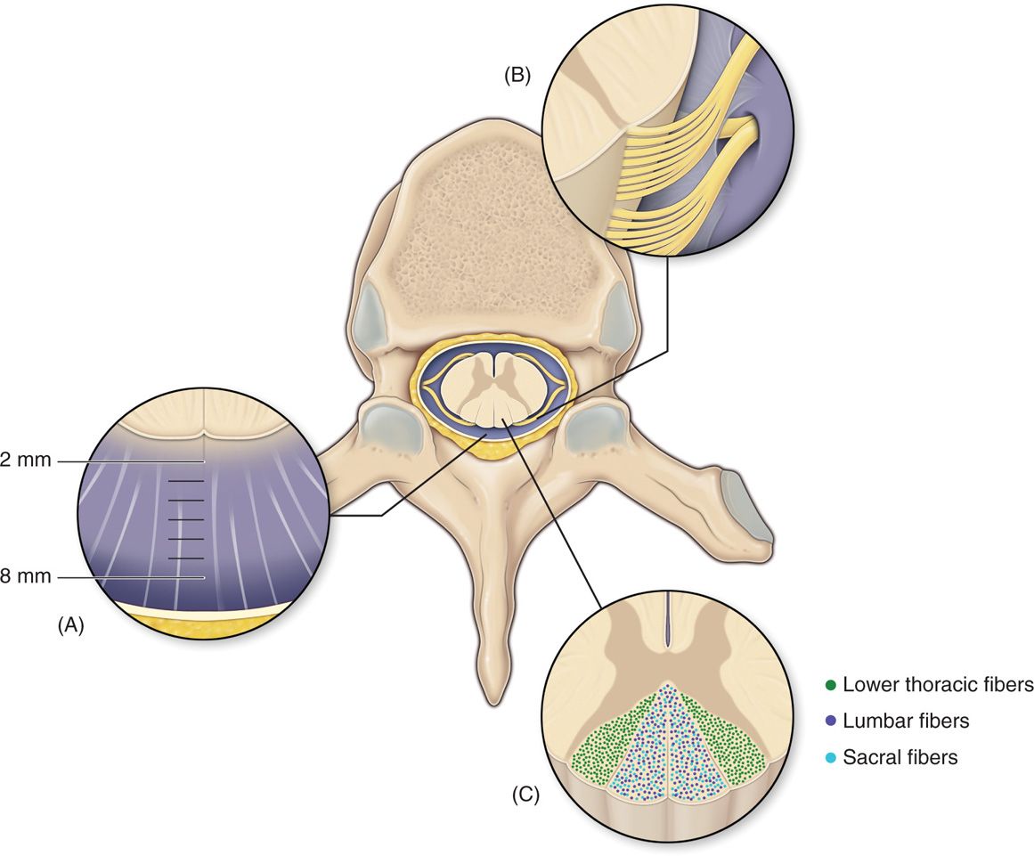
Figure 71-5. Anatomy of the spinal canal. The epidural space is circumferential wrapping around the dura and is bound by the ligamentum flavum posteriorly, the posterior longitudinal ligament and vertebral bodies anteriorly. Vertebral pedicles and intervertebral foramina with their penetrating nerve roots form the lateral borders. dCSF thickness is largest at T4-T8. Dorsal root entry zone (DREZ) borders dorsal columns.
PREOPERATIVE CONSIDERATIONS
• Informed consent. Both trial and permanent implant of SCS systems are invasive surgical procedures that carry inherent surgical risk. While the risks for serious adverse events are minimal compared to other spine surgical procedures, patients should be informed of the following potential complications:
![]() Bleeding
Bleeding
![]() Infection (including risk of meningitis)
Infection (including risk of meningitis)
![]() Spinal cord injury and paralysis
Spinal cord injury and paralysis
![]() Nerve damage associated with weakness and numbness
Nerve damage associated with weakness and numbness
Furthermore, patients should be made aware of the long-term risk of needing revision surgery due to:
![]() Reduced analgesic efficacy of SCS with time
Reduced analgesic efficacy of SCS with time
![]() Equipment malfunction with loss of stimulation
Equipment malfunction with loss of stimulation
![]() Lead migration or damage resulting in loss of stimulation
Lead migration or damage resulting in loss of stimulation
![]() Chronic pain (discomfort) around the implanted programmable generator (IPG) site or anchors
Chronic pain (discomfort) around the implanted programmable generator (IPG) site or anchors
• Coagulopathy. Anticoagulated patients who may undergo SCS trial or implant should be managed according to current American Society of Regional Anesthesia and Pain Medicine (ASRA) consensus guidelines for neuraxial anesthesia. However, adhering to guidelines does not result in absolute elimination of all risks of bleeding. The risks to be considered in an anticoagulated patient may extend beyond the preoperative period and include long-term potential epidural hematoma resulting from movement of the leads in the epidural space. Important points:
![]() Patients should always be asked about the medications they are currently taking, including vitamins and herbals.
Patients should always be asked about the medications they are currently taking, including vitamins and herbals.
![]() Coagulation screening tests should be ordered (or hematology consult) for patients suspected of bleeding disorder.
Coagulation screening tests should be ordered (or hematology consult) for patients suspected of bleeding disorder.
![]() ASRA guidelines need to be followed for SCS procedures in anticoagulated patients.
ASRA guidelines need to be followed for SCS procedures in anticoagulated patients.
• Examine the skin at operative field for skin breakage and erythema and other infection (cellulitis) signs.
• IV access should always be obtained for fluid administration, antibiotics, and sedation medications.
• Preoperative prophylactic antibiotics should always be administered within 1 hour of start of trial or incision for implant.
• Patients should be able to lie in a prone or a lateral decubitus position for a long period of time and communicate with the physician or representative aiding in programming of the device during testing stages of the procedures. The position should be adjusted to minimize the lumbar lordosis for lumbar entry procedures (Figure 71-6). The neck should be in flexion for cervical SCS procedures.
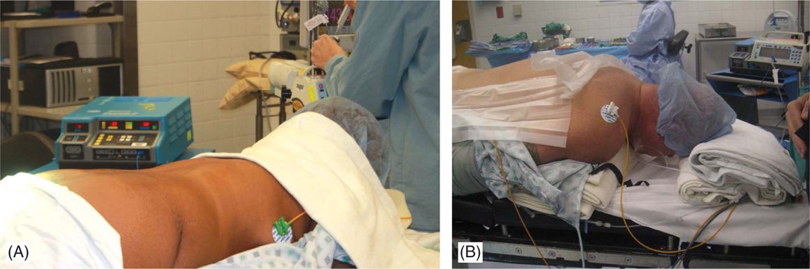
Figure 71-6. Patient positioning. Patient is placed in prone position and a bolster should be placed underneath the lower abdomen to reduce the lumbar lordosis and facilitate epidural access in the lumbar region (A). For cervical access, with patient positioned in prone position, a bolster is placed underneath the chest and another pillow or a soft roll at the forehead (B) with the head on flexed position.
TECHNICAL DETAILS OF PROCEDURE
Positioning of Patient
Physicians performing SCS placement should be actively involved in patient positioning as positional discomfort and lack of fluoroscopic clarity would compromise the success of the procedure. The patient is typically positioned in the prone position and occasionally in the lateral decubitus position on a padded surgical table.
• For lower thoracic lead tip, positioning should strive to minimize patient’s natural lumbar lordosis to facilitate needle entry into the interlaminar space (Figure 71-6A).
• Patient’s head may be turned to the side in cases where leads are not driven into the cervical region; otherwise it should be kept midline with the cervical spine flexed in a comfortable position (Figure 71-6B).
• In the prone position, a bolster should be placed underneath the lower abdomen to reduce the lumbar lordosis and facilitate epidural access in the lumbar region (Figure 71-6A).
• For cervical access, with patient positioned in prone position, a bolster is placed underneath the chest and another pillow or a soft roll at the forehead (Figure 71-6B).
• A bolster under the upper chest that allows neck flexion, facilitates lead entry and steering into the cervical epidural space (Figure 71-6B).
• In case of lumbar access, arm boards should be positioned in such a way that they do not impede fluoroscopic views whereas for cervical lead placement, the arms should be tucked to the side of the patient (Figure 71-6A and B).
Selection of Needles, Medications, and Equipment
Modified Tuohy needles are supplied with each SCS manufacturer’s kits and are used to introduce SCS leads. In preparation, a small gauge hypodermic needle is used for anesthetizing the skin and subcutaneous tissue at the point of needle entry and a 3.5-in-long spinal needle is used for deeper local anesthetic delivery along the planned path of the modified Tuohy needle. Meticulous local anesthesia delivered along the exact path of lead entry would allow the performance of the lead placement and testing portion of the procedure with minimal or no sedation. Lidocaine 0.5% to 1% or a mixture of lidocaine and bupivacaine is typically used for local anesthesia.
Equipment
The basic equipment for SCS includes leads, anchors to stabilize the leads, and an implantable pulse generator (IPG). Leads and anchors are supplied as a sterile kit opened at the instrument table. The IPG is provided also at implant time in a sterile box. There are two types of leads currently available: cylindrical percutaneous leads and surgical (paddle) leads.
Percutaneous Leads
Percutaneous leads are flexible cylindrical polyurethane catheters with multiple evenly spaced electrode contacts arranged at the distal end. Circumferential design of the electrodes results in the possibility of 360-degree dispersion of the stimulation current.
• Percutaneous leads contain either 4 or 8 contacts (quadripolar or octapolar). The general trend is to utilize octapolar leads for SCS stimulation and quadripolar for peripheral nerve and nerve field stimulation. Greater than 8 contact leads will be coming to the market and some have been FDA approved.
• Electrode contacts are small plates composed of platinum-iridium alloy ranging 3 to 6 mm in length.
• Edge-to-edge spacing of the electrodes ranges from 1 to 12 mm depending on the manufacturer and type of lead. Spacing of the contacts has been shown to influence steering of the electrical field and enhanced resolution of stimulation.
• Lead length is standard and varies with manufacturer. Commonly the lengths vary between 30 and 80 cm. Lead length should be taken into consideration for appropriate spine entry point and generator placement.
Anchors
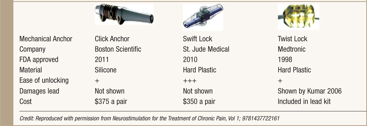
Anchors are used to stabilize the leads to fascia or the supraspinous ligament. Good anchoring technique plays a major role in prevention of lead migration—the most common etiology for future treatment failure and surgical revision. All SCS system manufacturers supply their anchoring systems. There are 2 types of anchors: traditional silicon anchors with suture sleeves and mechanical anchors. Mechanical anchors have been developed to provide better holding force than traditional anchors and to also bypass the step of tying the anchor to the lead (Table 71-1).
TABLE 71-1. Mechanical Anchors Developed by Three SCS System Manufacturers
Pulse Generators
Three types of generators are available: radiofrequency (RF), primary cell (non-rechargeable) battery, and rechargeable battery. RF systems are not used much anymore as fully implantable systems are widely available, more convenient and preferred by patients.
• Non-rechargeable systems (IPG) were introduced three decades ago and have a variable life span of 1 to 5 years depending on patient use and parameters of stimulation.
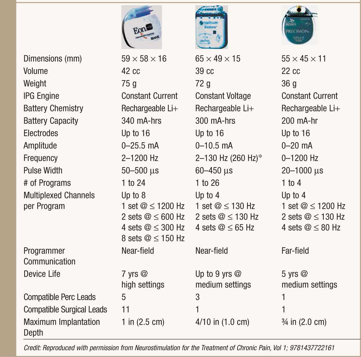
• Rechargeable IPGs offer renewable power source and a variable life span, typically longer than 5 years while maintaining high output stimulation (Table 71-2).
TABLE 71-2. Rechargeable IPG
Parameters of Stimulation
When initiating SCS, the minimum current at which patients perceive paresthesia is defined as the perception threshold (PT). As current continues to be increased, patients may experience discomfort at higher amplitudes. The minimum current at which patients perceive discomfort is defined as the discomfort threshold (DT). Typical stimulation is carried out between PT and DT.
Paresthesia coverage depends on the shape of the electrical field surrounding the nerve fibers as well as the recruitment of the nerve fibers. There are 3 variables characterizing the electrical stimulation of the spinal cord: frequency, amplitude, and pulse width. Fine tuning of the paresthesia field is achieved by modifying the following parameters:
• Amplitude (A, in mA or milliamperes). Affects the intensity and extent of paresthesiae. Increasing the amplitude expands the area of coverage but could result in uncomfortable stimulation. Typical range: 1.0 to 5 mA.
• Pulse width (PW, in μs or microseconds). PW is the duration of single delivered square stimulation pulse. Higher pulse width may help in recruiting smaller nerve fibers in the dorsal column. Pulse width range varies with IPG manufacturer with values ranging from 20 to 1000 μs.
• Frequency (F in Hz or hertz). Frequency is the number of pulses per second. Frequency affects the quality of paresthesia and may be perceived by patients as “smooth” sensation or more of a “thump” sensation.
The use of higher amplitudes, higher pulse widths, and higher frequencies would obviously increase the energy consumption and tax recharging frequency.
INTRAOPERATIVE TECHNICAL STEPS OF PERCUTANEOUS TRIAL OF SPINAL CORD STIMULATION
• Prior to implant of a spinal cord stimulation device, a trialing period ranging from 3 to 7 days or longer takes place.
• Trial success may not be related to duration of trial or number of leads, though a minimum duration of 3 days should be considered except under extenuating circumstances.
• The consensus of most of the literature suggests that >50% pain relief is the outcome for judging a successful SCS trial.
• A trial of SCS can be performed as a staged procedure or with no intention for lead reuse. If performed as staged procedure, an incision is made and leads are secured to deep fascia and an extension is tunneled and exteriorized to the contralateral side of future IPG implant site. In case of an unsuccessful trial, this would require a new surgical procedure to remove the leads.
• The overwhelming majority of percutaneous implanters place leads through a modified Tuohy needle with no intention to leave the lead in place for long-term use. These trial leads can be easily removed in the office without requirement of any surgical procedure.
Trial Procedure
1. Patient is placed in the prone or lateral decubitus position with optimal interlaminar space exposure and spine alignment.
2. Sterile techniques are followed throughout.
3. Epidural access is achieved with a modified Tuohy needle using the loss of resistance (LOR) technique under guidance of fluoroscopy.
4. Needle bevels are turned to facilitate lead steering (Figure 71-7A).
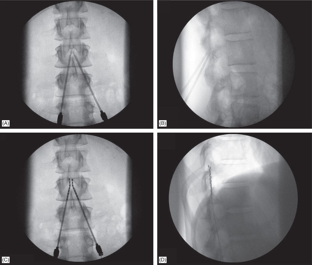
Figure 71-7. Technique of lead placement. Fluoroscopic views: (A) bilateral Tuohy needle placement; (B) lateral fluoroscopic view of confirmation of epidural access by both Tuohy needles; loss of resistance can be performed in this view; (C) lead steering into the epidural space; (D) later view confirms needle positioning on the posterior epidural space.
5. Lateral view is preferred while performing LOR (Figure 71-7B).
6. Needle entry level into the epidural space for percutaneous lead placement depends, in part, on anticipated final placement of the lead(s); and should be at least 2 to 3 vertebral levels below target lead tip position.
Technical Issues
• Common needle entry for lower extremity and/or axial low back pain occurs around the mid to upper lumbar region (Figure 71-8).
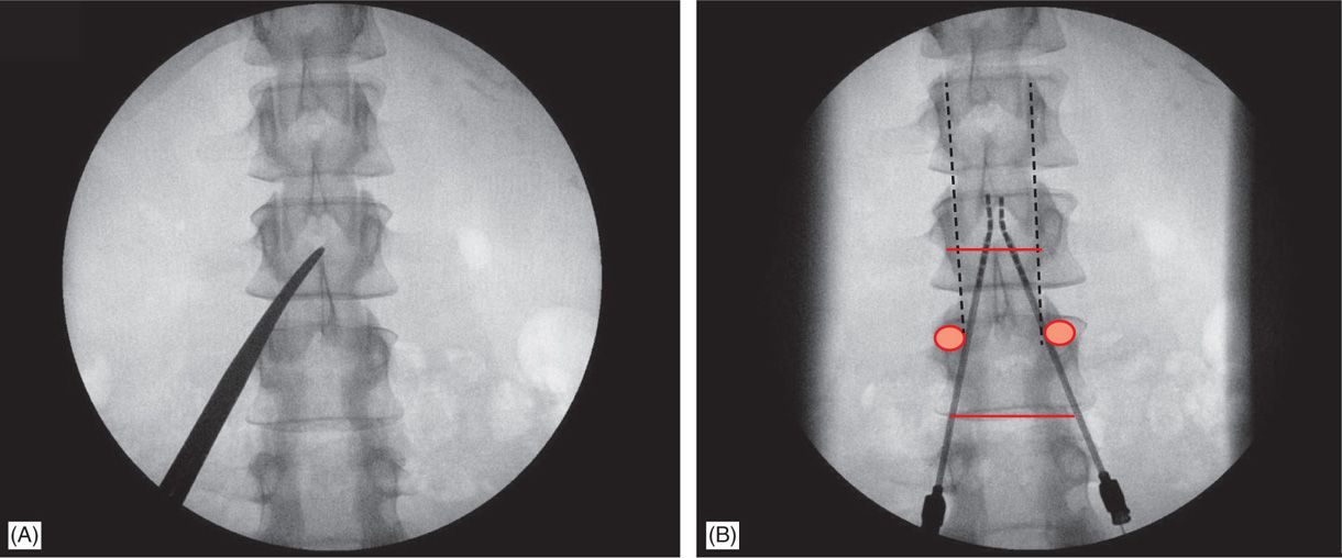
Figure 71-8. Technique of lead placement. Posteroanterior (PA) view is used initially to visualize spine anatomy and identify the anatomical landmarks which are marked by opaque instruments (A). Skin entry should occur at some point between the ipsilateral two pedicles below the desired interlaminar space, depending on patient’s body habitus and spinal anatomy (A and B). Needle entry into the epidural space should occur as close as possible to midline (B).
• Skin entry commonly is marked along a line joining the L2, L3, or L4 pedicles (Figure 71-8). Entry into the epidural space should be as flat as possible, depending in part, on the body habitus of the patient.
• Entry into the epidural space, should occur between one to two vertebral body levels cephalad to the skin entry point (Figure 71-8).
• Because the epidural space is obliterated in cases of previous laminectomy/spine fusion, entry into the epidural space should occur above such levels, at virgin sites.
• A paramedian approach should be used to avoid traction forces of the supraspinous and interspinous ligaments as well as the possibility of the spinous processes causing fracture of a lead placed through a midline approach.
• The percutaneous implanter should not hesitate to use a longer than standard epidural needle to ensure the angle of approach to the epidural space is shallow (<45 degrees angle with the skin whenever possible).
• Entry of the needle into the epidural space should occur as close as possible to the midline to ensure posterior placement of the epidural lead (Figures 71-7 and 71-8).
• A lateral view should be taken to ensure the lead has not migrated anteriorly in the epidural space (Figure 71-9C).
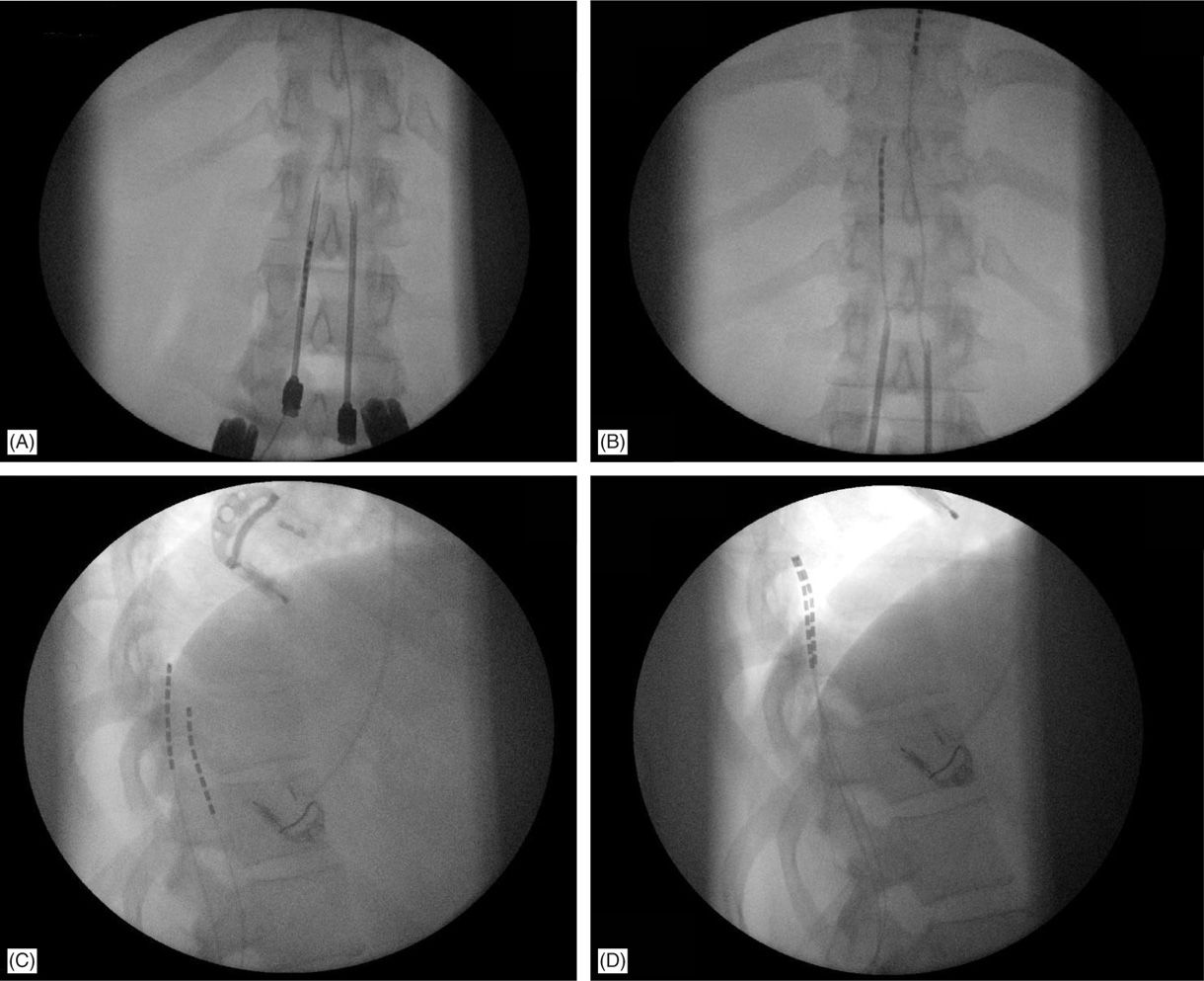
Figure 71-9. Lateral fluoroscopic view is necessary for appropriate lead placement. (A) Tuohy needle access in the epidural space; (B) leads are floated and steered smoothly cephalad into the epidural space toward the target continuously in the AP view; (C) lateral fluoroscopic view shows wrong placement of the left lead on the anterior epidural space; (D) lead was withdrawn and steered into posterior epidural space initially in the lateral view, than to appropriate location on AP view and final confirmation on the lateral view.
• Rotation of the bevel of a near-midline Tuohy needle will determine the initial steering direction of the leads into the epidural space.
• Leads are threaded though the needle and steered in the PA view, close to midline, after posterior epidural positioning is confirmed.
• Once lead tips are sited at the appropriate vertebral segment (see coverage segment: “Lead Location and Paresthesia Coverage”), they are connected through an extension to an external power source and stimulation testing would commence. During this phase, the physician’s interaction with the patient and the manufacturer representative assisting with stimulation parameter programming is important. Small movements in lead position and various stimulation electrode configuration patterns and parameters are employed to achieve >80% overlap between pain area and paresthesia coverage.
• Final lead placement should always be individualized to the patient’s response during intraoperative mapping:
![]() For upper extremity coverage, lead tips are commonly placed between C2 and C7. Needle insertion may occur in the upper thoracic region between T2 and T6 (Figure 71-10). A choice exists between the upper and lower thoracic region.
For upper extremity coverage, lead tips are commonly placed between C2 and C7. Needle insertion may occur in the upper thoracic region between T2 and T6 (Figure 71-10). A choice exists between the upper and lower thoracic region.
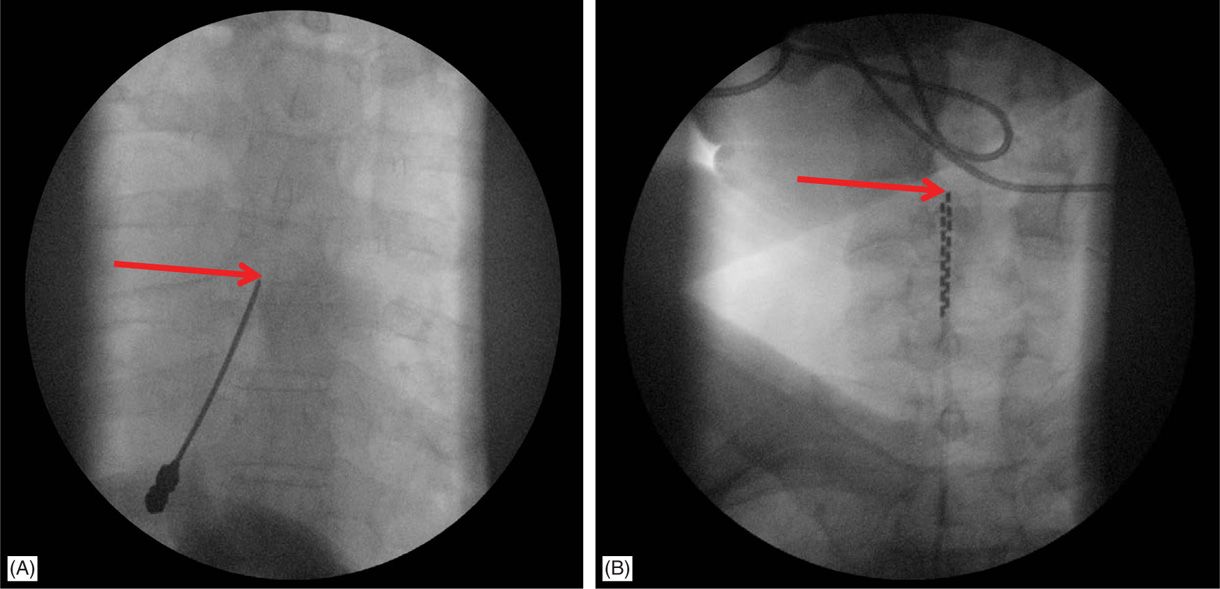
Figure 71-10. Cervical placement of SCS leads for upper extremity coverage. (A) Epidural access at T4-T5 intralaminar space is sought for cervical spinal cord stimulation; (B) leads are steered cephalad to C4-C6 for coverage of the upper extremity.
![]() The upper thoracic area is a stable and good site for needle placement. Skin entry location of T2 to T6 allows the needle to advance in a shallow orientation to the epidural space; however, placement at this level requires a high degree of operator skill and is not recommended for novices or for physicians with limited experience and limited volume of SCS trials.
The upper thoracic area is a stable and good site for needle placement. Skin entry location of T2 to T6 allows the needle to advance in a shallow orientation to the epidural space; however, placement at this level requires a high degree of operator skill and is not recommended for novices or for physicians with limited experience and limited volume of SCS trials.
![]() The mid-thoracic area, between T5 and T9, may be most difficult to access epidurally due to anatomic angulation of the spinous processes.
The mid-thoracic area, between T5 and T9, may be most difficult to access epidurally due to anatomic angulation of the spinous processes.
![]() Epidural entry into the lower thoracic spine is similar to entry into the upper lumbar epidural space.
Epidural entry into the lower thoracic spine is similar to entry into the upper lumbar epidural space.
![]() For coverage of the lower extremities, mid to low thoracic lead tip placement is common and entry into the epidural space is generally accomplished anywhere from T12-L1 to L4-L5 depending on anticipated final lead tip position.
For coverage of the lower extremities, mid to low thoracic lead tip placement is common and entry into the epidural space is generally accomplished anywhere from T12-L1 to L4-L5 depending on anticipated final lead tip position.
• Percutaneous leads should travel at least 2 vertebral bodies inside the epidural space for increased lead stability.
• Given sufficient pain relief (>50% relief over baseline levels) and pleasant experience with stimulation, leads are removed in physician’s office a few days after a temporary percutaneous trial and the patient and implanter typically come to a consensus to proceed with a permanent implant.
• Permanent implant is scheduled a few weeks after the trial which allows sufficient time for any minor tissue trauma to heal as well as any indolent infection from the trial to manifest prior to permanent implant.
• In the case of no or minimal pain relief, permanent implantation is not performed.
Lead Location and Paresthesia Coverage
The following lead locations have been typically mentioned to achieve specific coverage:
• High cervical regions such as C2 can cover regions of the posterior occiput and occasionally the lower jaw.
• C2-C4 stimulation provides coverage of the neck, shoulder, and upper extremities and the lower face as a result of involvement of the descending nucleus of the trigeminal nerve.
• C5-C6 stimulation affects the entire upper extremity including the hand.
• C7-T1 may cover the arms, anterior chest wall, or the axilla.
![]() Occasionally, placement between C4 and T1 may result in coverage of upper and lower extremities, particularly when using current fractionation.
Occasionally, placement between C4 and T1 may result in coverage of upper and lower extremities, particularly when using current fractionation.
• Lateral placement at T11-T12 covers the anterior thigh.
• T11-L1 can cover the posterior thigh and the foot.
• T8-T10 midline placement of the electrodes in general seems to provide the best coverage for lower extremity pain.
• Low back pain may be very difficult to cover because mid-thoracic stimulation can also affect the chest and abdominal wall and stimulation at lower levels preferentially recruits lower extremity fibers; T7-T8 levels are usual targets.
There have been case reports demonstrating 4 limb paresthesias with leads placed at C1-C2 (with retrograde paddle surgical leads) and in the lower cervical region (and down to T2; with percutaneous leads). This observation of 4-limb stimulation has been useful in the rare patient with pain in upper and lower extremities and may circumvent placement of a second generator and 2 additional leads.
Fluoroscopic Views
Fluoroscopic clarity of spine anatomy is aided by appropriate patient positioning on the surgical table.
• Posteroanterior (PA) view is used initially to visualize spine anatomy and identify the anatomical landmarks. A slight (5-10 degrees) caudal tilt helps aligning vertebral end plates of the upper lumbar spine. According to the entry level, in the PA view:
![]() Spinous processes should be identified and aligned precisely at vertebral midline.
Spinous processes should be identified and aligned precisely at vertebral midline.
![]() Vertebral end plates should be aligned to crisp, linear horizontal position.
Vertebral end plates should be aligned to crisp, linear horizontal position.
![]() The pedicles at the epidural entry level and 2 levels below should be identified.
The pedicles at the epidural entry level and 2 levels below should be identified.
![]() Skin entry should occur at some point between the ipsilateral 2 pedicles below the desired interlaminar space, depending on patient’s body habitus and spinal anatomy (Figure 71-8).
Skin entry should occur at some point between the ipsilateral 2 pedicles below the desired interlaminar space, depending on patient’s body habitus and spinal anatomy (Figure 71-8).
![]() Needle entry into the epidural space should occur as close as possible to midline (Figures 71-7A and 71-8B).
Needle entry into the epidural space should occur as close as possible to midline (Figures 71-7A and 71-8B).
• The lateral view is used to confirm needle tip positioning as well as to advance the Tuohy needle, especially when the “loss of resistance” (LOR) technique is ambiguous. Frequent comparison between AP and lateral views ensures correct needle tip positioning in the middle of the posterior epidural space.
• The lateral view is particularly useful in cases whereby 2 Tuohy needles are placed unilaterally in the same interlaminar level (Figure 71-11).
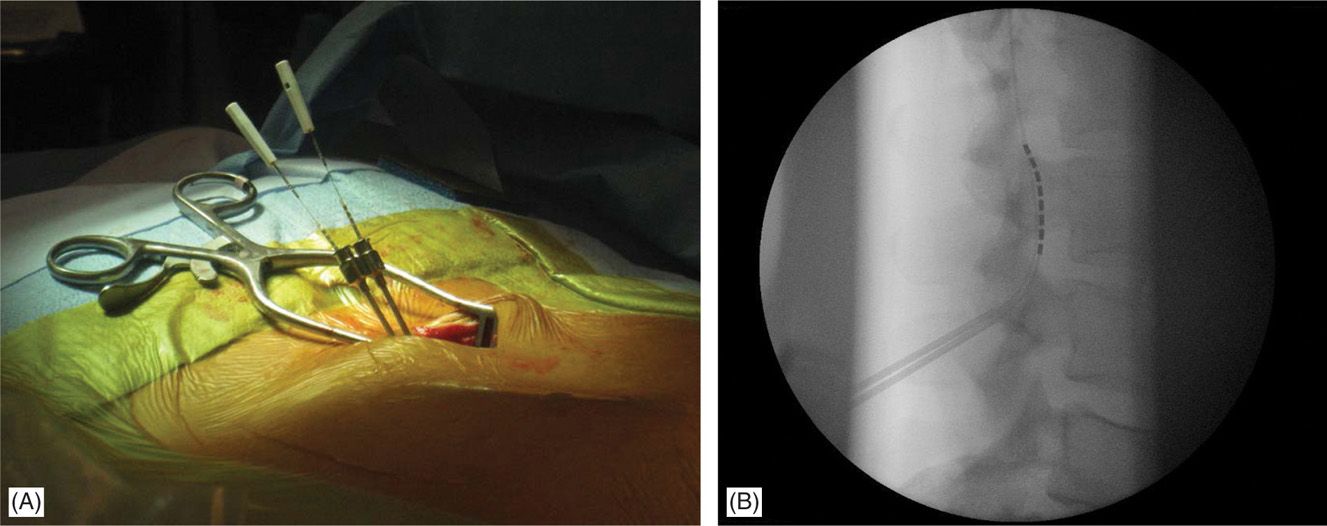
Figure 71-11. Lateral approach to SCS. Unilateral, same intralaminar space placement of Tuohy needles using lateral fluoroscopy (A). First needle confirmed in the epidural space serves also as a guide for the second needle access to epidural space (B).
• Lead steering is performed in PA view (Figures 71-7C, 71-9A and B, and 71-15B). However, the lateral view may be used when driving the lead, to confirm location in the posterior epidural space versus anterior epidural space (Figure 71-9C-D).
• Pulsed mode fluoroscopy (with half- or quarter-dose exposure, as opposed to continuous fluoroscopy) is helpful in reducing radiation exposure while steering the SCS lead to its final positioning, slightly off the midline over the dorsal column.
• Needle entry too far off midline and lead steering way off midline will likely result in erroneous placement of the lead in the anterior epidural space and that can be confirmed on lateral fluoroscopy (Figure 71-9C).
• Once final positioning is confirmed, including satisfactory patient paresthesias at acceptable programming parameters, a single fluoroscopic image is obtained as a reference.
• Lead anchoring is then performed, either to the supraspinous ligament or fascia in permanent implants or to skin in trials; another single frame roentgenogram is taken to confirm that the lead(s) did not move from the desired position.
Permanent Implant
Permanent implant generally follows a successful SCS trial. Percutaneous SCS implant is typically an outpatient procedure and patients are discharged with oral analgesics for postoperative pain and usually 2 to 3 days of antibiotic prophylaxis dependent also on risk factors and comorbidities.
• The implantable pulse generator (IPG) site is determined. Anatomical considerations, patient preferences and esthetics determine the IPG location. This position, along with skin entry point and lead tip target determine lead length.
• Prophylactic intravenous antibiotics should be administered within 1 hour of the permanent implant.
• The patient is taken to the OR and positioned on the surgical table (Figure 71-6A and B).
• Sterile surgical preparation takes place initially with a “defatting” isopropyl alcohol prep followed by chlorhexidine (Figure 71-12). Many implanters use an Ioban drape over the surgical site. Surgical gown, mask, and protective head and foot wear should be used.
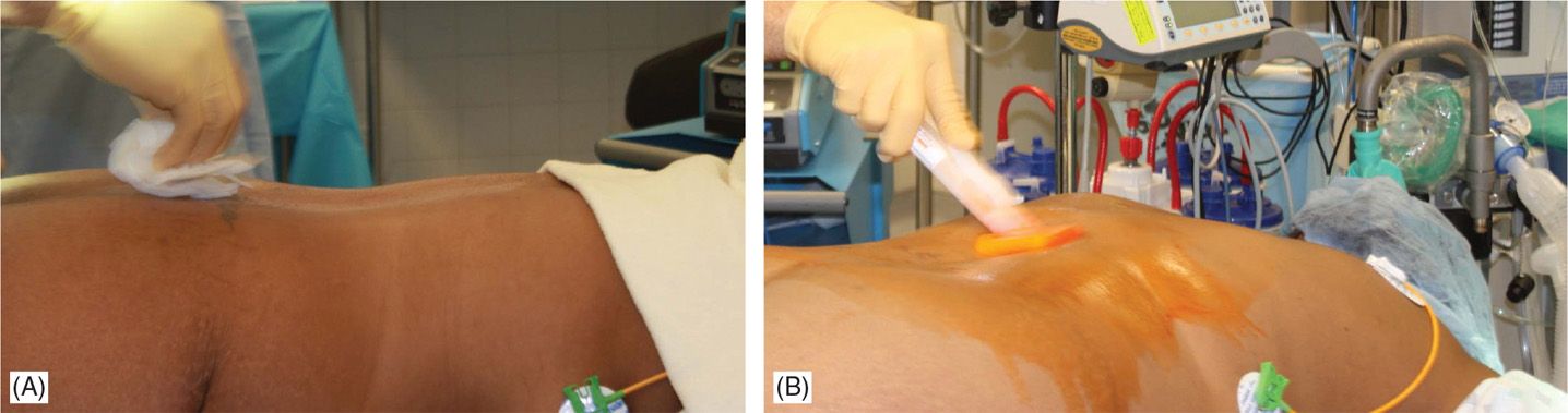
Figure 71-12. Procedure steps-operative field preparation. Sterile surgical prep takes place initially with defattening isopropyl alcohol (A) followed by chlorhexidine (B). Many implanters use an Ioban drape over the surgical site. Surgical gown, mask, and protective head and foot wear should be used.
• Fluoroscopy and opaque instruments are used to mark anatomical landmarks (Figures 71-8 and 71-13). Decision on the level of interlaminar space access is made. Sufficient local anesthetic is used to anesthetize the skin and needle trajectory.
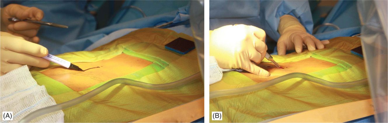
Figure 71-13. Procedure steps—fluoroscopic anatomy and incision. Fluoroscopic guidance and opaque instruments are used to identify the anatomical landmarks. After marking the incision line (A) starting from nearly 1.5 levels from intended intralaminar space a 4-5 cm incision is made (B).
• At this point, needle access for lead placement is achieved similarly to that described for the trial. A skin incision before skin needle entry (Figure 71-13B) or afterward with the modified Tuohy needle in place is made longitudinally (~5 cm) and dissection down to the fascia/supraspinous ligament is performed with the help of electrocautery (Figure 71-14A). Local anesthetic is applied along the needle path (Figure 71-14B). Hemostasis is achieved with electrocautery carefully, as the probe should not come in contact with the needle.
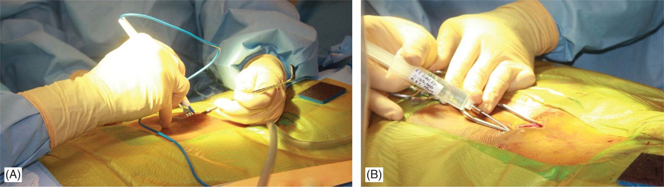
Figure 71-14. Procedure steps—fluoroscopic anatomy and incision. Sharp dissection to the level of fascia is commenced and electrocautery is used for good hemostasis (A). Using Tuohy needle and following a paramedian trajectory tissues layers are anesthetized with a mixture of lidocaine 0.5% and bupivacaine 0.25%.
• Two leads may be placed at the same interlaminar space using a paramedian approach with one needle penetrating on each side of midline. However, superimposed placement of both needles from the same paramedian side is also useful (Figure 71-11). The first needle placed would serve as an excellent marker for where the posterior epidural space lies on the lateral view. Caution should be used not to damage the lead with the second needle; hence, placement of the second needle should occur inferior to the first needle when both needles enter the epidural space on the same side. A paramedian approach avoids tension forces of the supraspinous and interspinous ligaments on the lead; as well as avoids spinous processes from shearing or fracturing the lead as might occur with a midline approach.
Entry into the epidural space should be as flat as possible, depending in part on the body habitus of the patient (Figure 71-15A). Entry into the epidural space should occur between 1 to 2 vertebral levels cephalad to the fluoroscopic skin entry point (Figure 71-8). Implanters may access the epidural space using fluoroscopic guidance in either PA or lateral position (Figures 71-7B and 71-8). The latter, however, requires familiarity with the posterior epidural line in this view. Lead steering can be is performed in AP view and under live fluoroscopy for exact positioning (Figure 71-15B-D). Occasionally a combination of epidural and subcutaneous leads is used to achieve a better coverage for low axial postlaminectomy pain (Figure 71-16).
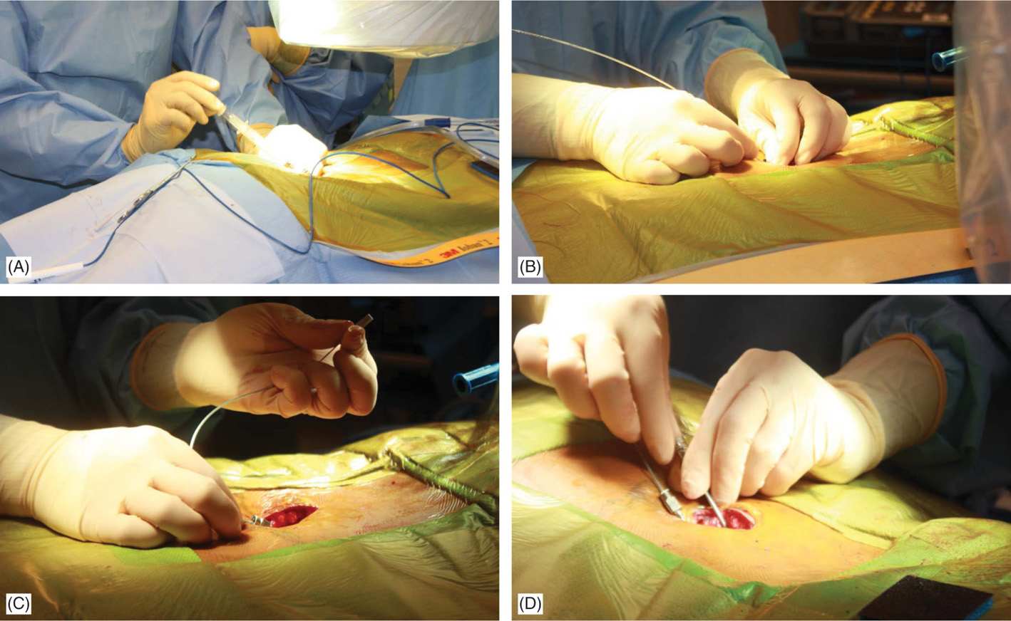
Figure 71-15. Procedure steps—lead placement. Loss of resistance is performed using a glass syringe and fluoroscopic guidance with AP or lateral views. Entry into the epidural space should be as close as possible to each side of fluoroscopic spinal cord midline (A). Post epidural access lead should be floated without much resistance in the epidural space (B). Lead is steered into the epidural space to the desired level (C). Rotating the bevel of the Tuohy needle can change the initial lead direction as desired (D).
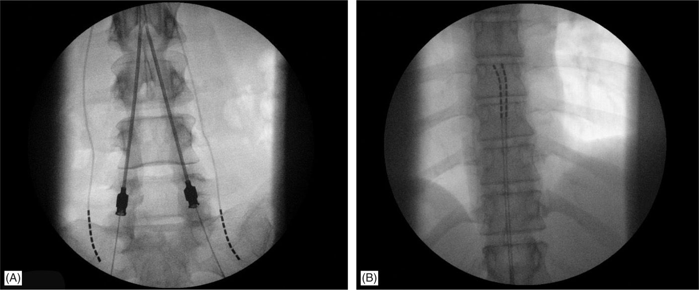
Figure 71-16. Combination of epidural and subcutaneous lead placement on a patient with postlaminectomy syndrome.
A lateral view should be taken to ensure the lead has not migrated anteriorly in the epidural space (Figure 71-9C), even though patients may experience discomfort during steering in the anterior epidural space or stimulation would result in muscle twitching.
SUBCUTANEOUS CUT-DOWN AND LEAD ANCHORING TECHNIQUES
After lead final placement, the fluoroscopic view would serve as a guide to ensure no change in the position of the leads has occurred. Meticulous anchoring of the leads is essential to prevent subsequent migration of the lead array. Anchors should be sited as proximally as possible on the lead with the proximal part of the anchor end dipping into the deep fascial tissue.
Nonabsorbable sutures should be placed into deep fascial planes or around the supraspinous ligament that will hold the anchor in place through its suture sleeves.
Currently, all manufacturers have mechanical anchors (Table 71-1) that secure the lead independent of the need to tie a suture around both lead and anchor. A suture is still taken through the fascia/supraspinous ligament to secure the mechanical anchor/lead complex through the suture sleeves of the anchor.
Frequent fluoroscopic images during the anchoring process and a final fluoroscopic image in both the PA and lateral views at the end of this process ensures that there has been no lead migration.
Generator Site Location and Preparation
• Generators can be placed in the buttock, the abdominal wall, the flank, along the mid-axillary line, or in the subclavicular area (for cervical leads with upper thoracic needle placement). For buttock placement, the generator is placed above where the patient sits but below the belt line. However, generator placement in the buttock may predispose patients more to lead migration. A single incision generator placement may be performed just off the midline in patients whose body habitus may allow such positioning (Figures 71-17 and 71-18).
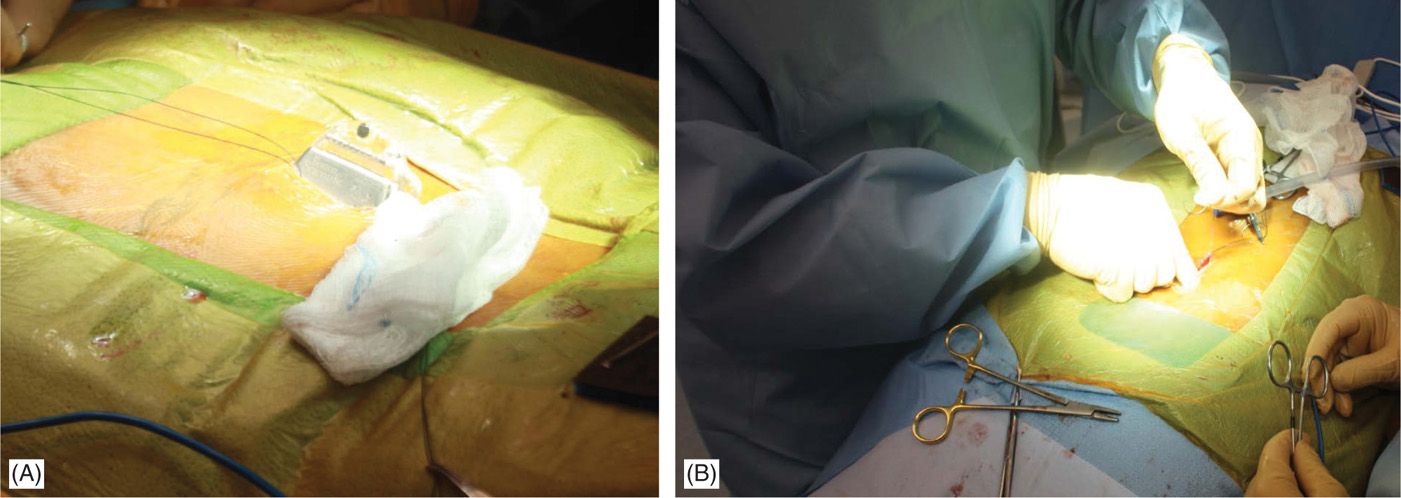
Figure 71-17. Procedure steps—single incision technique. A pocked is made by dissecting above the fascia laterally (left or right) below the incision edge (A). IPG is fixed to fascia with two Surgilon sutures (B) to prevent rotation or even erosion.
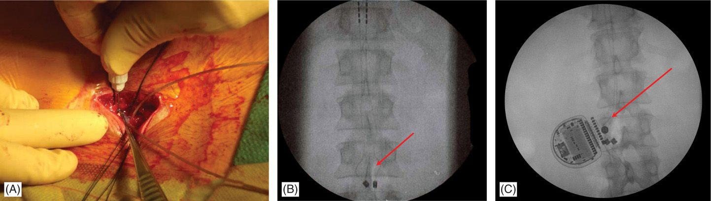
Figure 71-18. Single incision technique images. Advantages of this technique are reduced operating time and less postoperative pain. (A) Leads are secured onto fascia and through the same incision a subcutaneous pocked is made by careful dissection just above the fascia; (B) fluoroscopic view of the anchored leads; (C) fluoroscopic view of the IPG and anchors. Single incision technique (no need for tunneling; IPG placed 2-4 cm from anatomical midline; system implanted through a single incision).
• The depth of the pocket is commonly 1 to 3 cm and recommendations vary among the companies for actual depth of generator placement. Ideally, the generator is placed deep enough to avoid subsequent discomfort or erosion but superficial enough to allow for recharging and interrogation of the system with subsequent programming.
• When the generator is not sited at the lead(s) incision site, the lead(s) is/are tunneled from the anchor site to the pocket using a specialized tunneling device. It is advisable to leave a strain relief loop in the back incision as insurance against subsequent patient movement that might dislodge the lead(s) or cause migration.
• The electrical contact sites on the lead should be inspected for blood or tissue products. If tainted, the lead contacts should be cleaned with a wet, then dry, sponge prior to insertion into the generator. After connecting to the generator, excess lead is coiled and maintained underneath the generator. The IPG is placed with the inscription up toward the skin side.
• The integrity of the system should be confirmed with an impedance check prior to closure.
• The generator is sutured into the pocket to prevent its migration, flipping over, or twiddling by the patient. A final AP and lateral fluoroscopic image is obtained to demonstrate no migration has occurred during the anchoring process.
• In 2006, Pyles introduced the notion of single incision for the implantation of the SCS leads and IPG device in the lumbar spine. Hayek reported at the International Neuromodulation Society meeting on 26 patients receiving single incision SCS implants (Figures 71-17 and 71-18). Kumar and colleagues suggested that the traditional placement of the generator in the buttock pocket might lead to increased strain and fulcrum effect on the leads and anchors. Having only one incision may also decrease the amount of postoperative pain that patients experience. There is also reduced operating time that may reduce the likelihood of time-sensitive complications such as infection, which usually occurs at the generator incision site. A potential complication that is unique to this technique is that revision surgery may be more difficult if the generator is enveloped in the same planes of scar tissue as the electrodes and the anchors; should an infection occur, the potential of spread to the epidural space may be higher given proximity of the generator to the spine.
POSTPROCEDURE CONSIDERATIONS
• The patient should be followed up at the clinic on postoperative day 5-7.
• The implanted patient should be encouraged to call with any signs of infections such as fever, exquisite pain at generator site, skin erythema and excessive edema.
• Patients are advised to call the pain service for any procedure-related complications and/or any unexpected neurological deficit.
• Patients should be monitored closely for the following: fever, bleeding, numbness, exacerbation of symptoms, neurological deficits, weakness, extreme pain, and positional headache suggesting dural puncture. Most common neurological complication in SCS implantation procedures is inadvertent dural puncture. Reports in the literature indicate an incidence of less than 1% in experienced hands.
MONITORING OF POTENTIAL COMPLICATIONS
Most complications of SCS are not life threatening and can be resolved by explanation of the system:
• Technical complications include electrode migration, electrode breakage, hardware malfunction, and other complications related to the hardware.
• Biological complications include infection, seroma, headache, neurological sequelae, pain at the implantation site, and allergic reaction.
• Other complications include undesirable stimulation, changes in stimulation with position changes, system tolerance, and skin erosion.
CLINICAL PEARLS AND PITFALLS
Clinical Pearls
• A shallow needle entry angle into the epidural space greatly facilitates lead placement.
• Needle entry into the epidural space should occur as close as possible to the anatomic midline (spinous process).
• Leads should be advanced under fluoroscopy while maintaining a course along or just off the anatomic midline in a posteroanterior view.
• Percutaneous leads should travel at least 2 vertebral bodies inside the epidural space to allow for improved lead stability.
• Careful anchoring of the leads and placing strain relief loops may decrease the risk of lead migration.
• Mechanical anchors may reduce the risk of lead migration.
Pitfalls
• Proper training and background is an absolute prerequisite to practicing SCS.
• Surgeon’s experience and careful patient selection are important considerations for curbing SCS complications.
• Novices or practitioners with limited SCS experience or volume of cases should not attempt cervical SCS placement and should refrain from tackling complex cases.
• Antibiotic prophylaxis and good surgical skills are likely to result in lower infection rates.
• Overuse of the therapy may have significant untoward consequences.
Related posts:


Stay updated, free articles. Join our Telegram channel

Full access? Get Clinical Tree


