CHAPTER 27
Sacroiliac Joint Denervation Using Synergy System
INTRODUCTION
The sacroiliac (SI) joint is a common source of chronic low back pain (LBP) with a prevalence rate of 13% to 30%.1–6 There is mounting evidence that radiofrequency (RF) neurolysis may provide long-term analgesia in this patient population. Techniques for RF neurolysis using conventional RF electrodes have been reported achieving modest outcomes.7–9 More recently, the use of novel cooled RF electrodes for RF neurolysis of the sacroiliac joint provided clinically meaningful efficacy over longer time intervals.10–12
Factors leading to a successful outcome following RF neurolysis include adequate diagnosis and accurate electrode placement, which relies on a good understanding of the neuroanatomy.13,14 Accurate electrode placement may be particularly important when treating sacroiliac-mediated pain as the precise innervation of the SI joint has yet to be elucidated. A review of the literature demonstrates that the L5 dorsal ramus and the lateral branches of the S1-S3 are frequently implicated in SI joint pain.1–14 The L5 dorsal ramus is reliably accessible at the lateral base of the S1 superior articular pillar (Figure 27-1). It courses along the junction formed between the base of the S1 superior articular process (SAP) and the superior edge of the sacral ala, while the lateral branches of the sacral dorsal roots do maintain an unpredictable distribution across the posterior sacrum.1–14
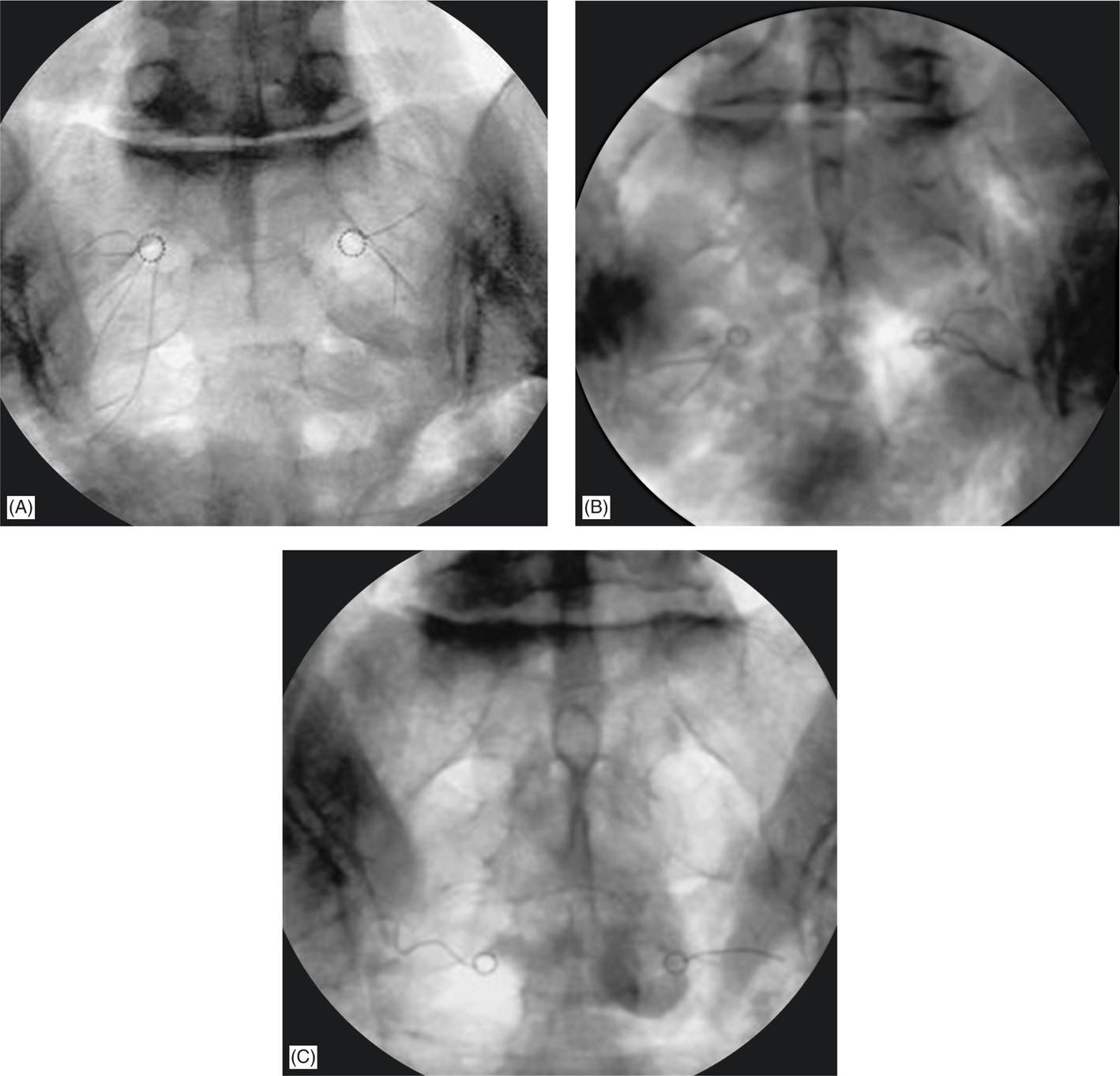
Figure 27-1. Anatomical position of dorsal ramus of the L5 nerve root. Maximum neural coagulation is achieved by placing the electrode adjacent and parallel to the course of nerve along the base of the SAP (A and B). The target point for electrode insertion is then identified by rotating the C-arm of the fluoroscope until the lateral edge of the S1 SAP is clearly visible. Once the target point is identified, the electrode is inserted using the “tunnel view.” The trajectory of the electrode is along the sagittal plane to ensure placement of the electrode along the course of the L5DR.
RELEVANT ANATOMY
• Dissection studies revealed that the upper dorsal portion of the SI joint is primarily innervated by the posterior dorsal ramus of L5, and the lateral branches of S1-S3 (Figures 27-1 and 27-2).
• Complete denervation of these nerves should provide at least partial sacroiliac pain relief in patients whose pain is posteriorly mediated.
• Thus, the L5 dorsal ramus is lesioned as standard practice, in addition to the lateral branches of S1-S3, to denervate the SI joint using cooled RF (Figure 27-3).
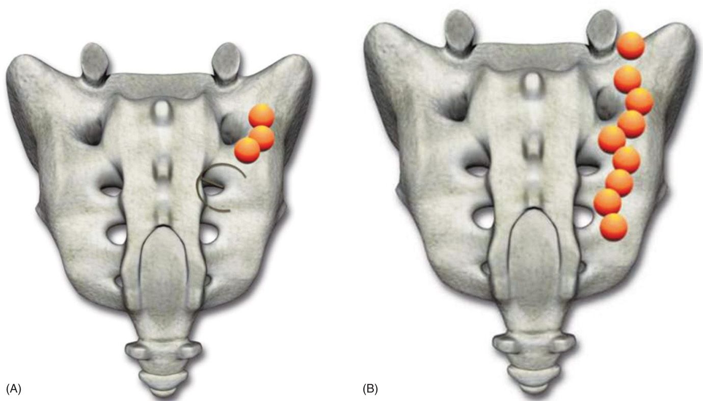
Figure 27-2. RF Lesions should be 8 to 10 mm from lateral edge of the sacral foramina. Target sites should be no more than 50 degrees apart (1:40 on a clock face) to achieve optimal lesion overlap. Epsilon (A) is used to judge distance for lesioning 8 to 10 mm from the lateral edge of the posterior foraminal aperture. Epsilon indicates appropriate spacing between target sites; 2:30, 4:00, 5:30 (right) at S1 and S2 and 2:30 and 5:30 for S3 (A and B). (Reproduced with permission from Kimberly-Clark Corporation.)
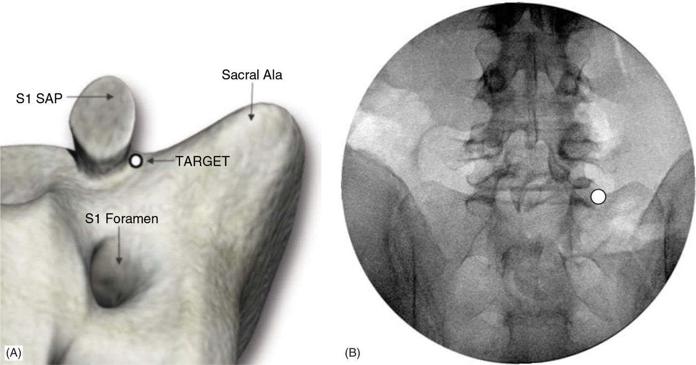
Figure 27-3. Due to the spherical nature of a cooled RF lesion, variation electrode trajectory would have no effect on the orientation of lesion. The targeted lateral sacral branches are maximally coagulated when tip of the cooled RF electrode is positioned with sufficient proximity to any branches, regardless of trajectory. Here illustrated is a spherical nature of achieved lesion when cooled RF is used via synergy system. (Reproduced with permission from Kimberly-Clark Corporation.)
The advantages of cooled RF electrode are:
• It creates larger lesions than conventional RF electrodes (Figures 27-3 and 27-4).
• These larger lesions provide a means of overcoming the anatomical variation of the target nerves and are more likely to interrupt the afferent lateral branches. These lesions are created by the much larger focal energy delivered.
• The circulating water removes heat from the tissue adjacent to the electrode, allowing power delivery to be increased without causing high impedance and tissue charring around the electrode (Figures 27-3 to 27-5).
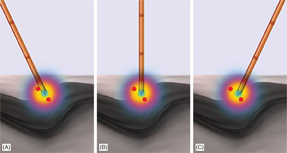
Figure 27-4. (A) Three 27-gauge spinal needles are shown piercing the skin over the sacral area. (B) A 27-gauge 3.5-in Quincke needles are positioned into most lateral aspect of S1, S2, S3 posterior sacral foramina under AP imaging. Proper positioning is then confirmed under lateral view. (Reproduced with permission from Kimberly-Clark Corporation.)
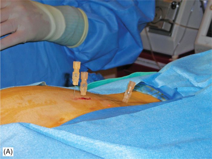
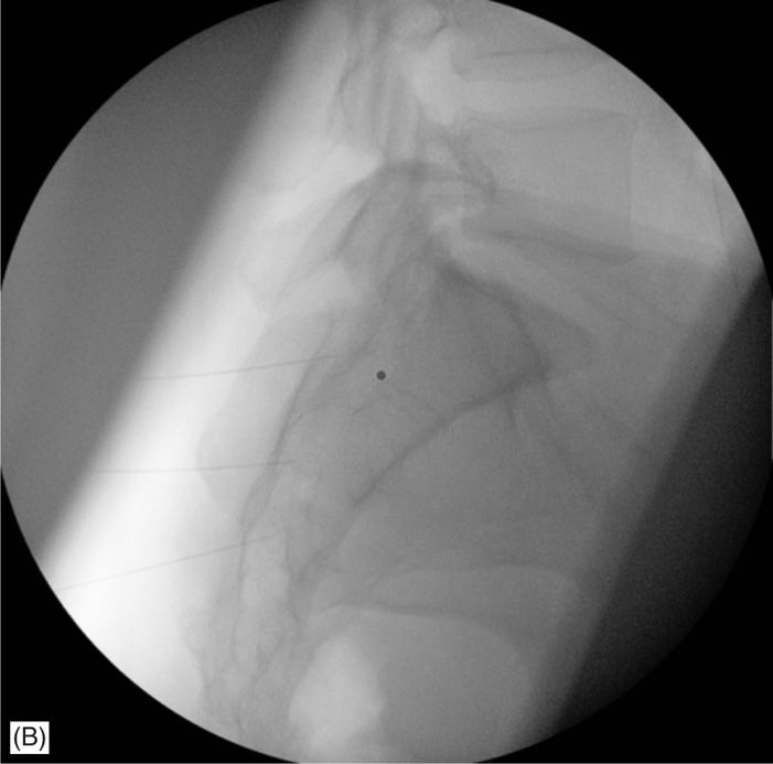
Figure 27-5. (A) Shown here (middle, black) is a cooled electrode inserted via 1 of 2 introducers placed appropriately in the sacral area. The electrode is connected to the generator via electrical cable (shown black) and the tubing used for electrode cooling by the water pump (shown transparent). (B) Two introducers are needed to facilitate the procedure, for example, while the ablation is conducted using electrode positioned via 1 of the introducers, other is being repositioned under fluoroscopy.
BASIC CONCERNS AND CONSIDERATIONS
Patient Selection
Candidates for lateral branch denervation using the Pain Management Synergy System must have a history of chronic back pain originating below the L5 spinal level for >6 months and must meet the following selection criteria.
Selection Criteria/Indications
Criteria for idiopathic sacroiliac region pain are:
• Predominant axial/mechanical pain below L5.
• >80% pain relief from two separate, low-volume, high-concentration intra-articular blocks.
• Blocks should be performed with fluorographic confirmation of needle placement and joint capsule integrity using both anterior-posterior and lateral views.
• Positive indication of physical examination (Fortin, Patrick, Genslean, etc).
• Chronic pain for >6 months.
• Failure to achieve adequate improvement with comprehensive nonoperative treatment at minimum: nonsteroidal anti-inflammatory and physical therapy.
• Other possible causes of low back pain have been ruled out.
• No indication of intervertebral disc involvement, and failure to obtain prolonged improvement from facet injections, or RF rhizotomies.
Contraindications
Patients will be excluded if they meet any of the following criteria:
• New neurologic deficit
• Spinal pathology that may impede recovery such as spina bifida occulta, spondylolisthesis at L5/S1, or severe scoliosis
• Pregnancy
• Systemic infection or localized infection at the anticipated introducer entry site
• History of coagulopathy or unexplained bleeding
Relative Contraindications
• Irreversible psychological barriers to recovery
• Radiculopathy
• Immunosuppression (eg, AIDS, cancer, diabetes, other surgery within last 3 months)
PREOPERATIVE CONSIDERATIONS
Fluoroscopic Views
• Start with anterior-posterior imaging of the L5/S1 disc space with slight cranial tilt to open the S1 and S2 sacral foramina on the operative side. This facilitates placement of the 27-gauge 3.5-in Quincke needles into the most lateral aspect of S1, S2, and S3 posterior sacral foramina as the internal reference points.
• Lateral views to confirm proper marker placement and to confirm the RF electrode lesioning tips are not in the canal.
Equipment
• Three 27-gauge 3.5-in spinal needles to be used as internal reference points
• Epsilon ruler for guidance
• Three 17-gauge cold radiofrequency synergy introducer
• Synergy radiofrequency probe
• 10-mL syringe for local anesthetic
• 25-gauge 1.5-in needle for local anesthesia
Medications
• 0.5% lidocaine for local anesthesia
• 2% lidocaine for anesthesia prior to lesioning
• 0.5% bupivacaine for anesthesia after lesioning
Brief Overview
• Moderate sedation is needed and an optional bowel prep.
• Lesions should be 8 to 10 mm from lateral edge of foramen.
• Target sites should be no more than 50 degree apart (1:40 on a clock face) to achieve lesion overlap (see Schematic 1), and only one introducer entry point through the skin at each level (3 o’clock for a right procedure).
• The Epsilon is used to judge distance for lesioning, which is 8-10 mm from the lateral edge of the posterior sacral foramina (PSFA).
• Epsilon indicates appropriate spacing between target sites.
• S1 and S2: 2:30, 4:00, 5:30 (for right) positions.
• S3: 2:30 and 5:30 positions.
• Lesion DR L5 (1 lesion).
• Set temperature at 60°C to achieve target tissue temperature for 2:05 minutes; 25 second ramp time.
Procedural Technique
• The patient is placed in the prone position with a pillow under the abdomen to reduce lumbar lordotic curvature.
• Continuous hemodynamic monitoring is initiated including blood pressure and pulse oximetry. IV sedation is administered incrementally to allow the patient to remain comfortable and conversant throughout the procedure.
• C-arm A/P fluoroscopy with cranial tilt is used to visualize the sacrum at the L5/S1 disc space.
• The skin is infiltrated with 0.5% lidocaine over the desired target entry sites after sterile prep and drape.
• Three 27-gauge 3.5-in Quincke needles are placed into the S1, S2, and S3 PSFA under anterior-posterior (AP) view to establish internal reference points (Figure 27-4).
• Beginning at the S1 level, a 17-gauge cold radiofrequency synergy introducer with stylet is inserted at the 3 o’clock (for right reference) position (Figure 27-5) and advanced until bony contact with the posterior sacrum.
• The introducer width is measured with Epsilon so that the tip is 8 to 10 mm from the lateral edge of the PSFA (Figure 27-2).
• The distance between the introducer and the aperture of PSFA of S1 was measured using the Epsilon ruler (Baylis Medical Company, Montreal; Figure 27-2). A depth marker is fixed to the level of the skin and lateral fluoroscopy is used to confirm proper placement outside of the canal (Figure 27-6). The stylet is removed.
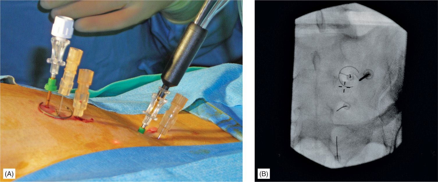
Figure 27-6. Assessment of the trocar with introducer and electrode depth. Adequate depth of the trocar with introducer needs to be achieved with tip of the trocar lying on the sacral plate (upper needle shade). As the electrode is 2 mm shorter than trocar, there is an intentional gap from the sacral plate (lower needle shade). This would allow better heat dissipation and should not be corrected by pushing electrode deeper to the surface of the sacral plate.
• The RF probe is subsequently inserted via the same introducer. Correct probe placement is confirmed in the lateral view and should be slightly off bone (Figure 27-6).
• RF energy is delivered for 2 minutes and 30 seconds at 60°C as the target electrode temperature.
![]() Three lesions are created at the S1 level. They are about 1 cm apart from one another using the Epsilon ruler, creating a strip of lesioned tissue lateral to the S1 foramen.
Three lesions are created at the S1 level. They are about 1 cm apart from one another using the Epsilon ruler, creating a strip of lesioned tissue lateral to the S1 foramen.
![]() This same procedure is repeated for each subsequent sacral level; however, only two lesions are created at S3 (Figure 27-2).
This same procedure is repeated for each subsequent sacral level; however, only two lesions are created at S3 (Figure 27-2).
• The notch between the ala of the sacrum and the superior articular process (SAP) of the sacrum is visualized in the AP view for L5DR denervation (Figures 27-2 and 27-7).
![]() 0.5% lidocaine is used for local skin anesthesia at this site.
0.5% lidocaine is used for local skin anesthesia at this site.
• The 17-gauge cold radiofrequency synergy introducer is inserted through the skin just lateral and inferior to the target point and directed toward the notch.
![]() The introducer is advanced until osseous contact at the base of the S1 SAP at its lateral midline (Figures 27-1 and 27-7).
The introducer is advanced until osseous contact at the base of the S1 SAP at its lateral midline (Figures 27-1 and 27-7).
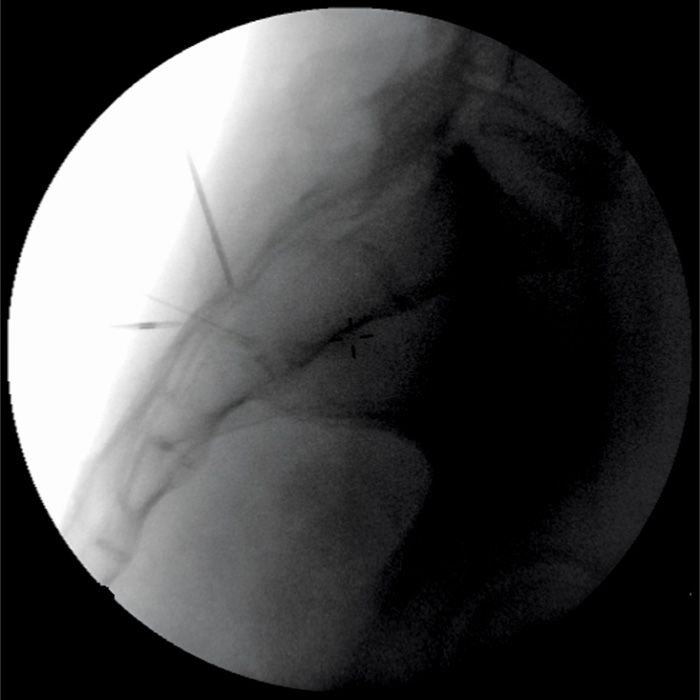
Figure 27-7. Anterior-posterior view of the cooled radiofrequency electrode positioned just lateral to the base of SAP.
• The depth of insertion is confirmed in the lateral view where the introducer tip is advanced no further ventral than the AP midline of the SAP, the z-joint space (Figure 27-8). This is to avoid injury to the segmental nerve root.
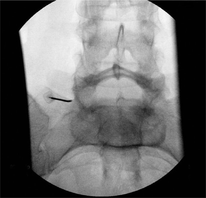
Figure 27-8. Lateral view of appropriately positioned introducer for the insertion of the cooled RF electrode. The tip of the trocar with introducer (and later RF electrode) is positioned posterior to the midline of the lateral fluoroscopic width of SAP.
• The stylet is removed and subsequently replaced with the cooled RF electrode.
![]() 1 to 2 mL of 0.5% bupivacaine is injected after lesioning.
1 to 2 mL of 0.5% bupivacaine is injected after lesioning.
• Again, RF energy is delivered for 2 minutes and 30 seconds at 60°C as the target electrode temperature. A lesion was created around the tip of the electrode using the Pain Management Generator (Baylis Medical Company, Montreal) at a target temperature of 60°C for 2 minutes and 30 seconds.
• Optionally, a second lesion is created 6 to 8 mm inferior to the initial target location but with the same needle entry point.
• The patient is then monitored prior to discharge.
POSTPROCEDURE FOLLOW-UP
Complications
Most complications are minor and consistent with lumbar/sacral neurectomy.
• Some patients may experience increased pain which is typically transient and resolves within 6 weeks.
• Localized numbness over the medial quadrant of the buttock.
• Increased lower back pain.
• Prolonged itching.
Potential Complications
• Infection
• Bleeding
• Osteitis or periostitis
CLINICAL PEARLS
• Cooled RF temperatures capable of coagulating nerve tissues are achieved at a distance of 4 to 6 mm from the electrode. Margin of safety need to be maintained and not to be confused with much lesser forward heat dissipation from conventional electrodes.
• The use of the cooled RF electrode to lesion the L5DR (and not conventional RF electrode) may have several advantages, to maximize the size of an effective lesion, simplify the cooled RF procedure, and to minimize patient discomfort.
• If higher impendence than the 500 ohm is observed, the electrode repositioning needs to be performed by reintroducing the stylet. Electrode itself should not be excessively manipulated.
• Repeated lateral fluoroscopic views add to the safety of this procedure, preventing unintended placement into posterior sacral foramina.
Related posts:


Stay updated, free articles. Join our Telegram channel

Full access? Get Clinical Tree


