Pulmonary Artery Catheterization
Harvey Steven Reich
Since their introduction into clinical practice in 1970 by Swan et al. [1], balloon-tipped, flow-directed pulmonary artery (PA) catheters have found widespread use in the clinical management of critically ill patients. However, in recent years, both the safety and efficacy of these catheters have been brought into question. In this chapter, I review the physiologic basis for their use, some history regarding their development and use, the concerns raised about their use, and suggestions for appropriate use of the catheters and the information obtained from them.
Physiologic Rationale for Use of the Pulmonary Artery Catheter
In unstable situations, during which hemodynamic changes often occur rapidly, clinical evaluation may be misleading [2]. PA catheters allow for direct and indirect measurement of several major determinants and consequences of cardiac per-formance—preload, afterload, cardiac output (CO)—thereby supplying additional data to aid in clinical decision making [3].
Cardiac function depends on the relationship between muscle length (preload), the load on the muscle (afterload), and the intrinsic property of contractility. Until the development of the flow-directed PA catheter, there was no way to assess all of these using one instrument in a clinically useful way at bedside. The catheter allows the reflection of right ventricular (RV) preload (right atrial pressure), RV afterload (PA pressure), left ventricular preload—PA occlusion pressure (PAOP) or pulmonary capillary wedge pressure (PCWP)—and contractility (stroke volume or CO). Left ventricular afterload is reflected by the systemic arterial pressure. This information allows the calculation of numerous parameters, including vascular resistances. No other tool allows the gathering of such a large amount of information.
Controversies Regarding Use of The Pulmonary Artery Catheter
Despite all of the advantages of the PA catheter, a number of clinical studies have been published in the past decade that have shown either no benefit or an increased risk of morbidity or mortality associated with its use. (See Table 4-1 for a summary of the evidence for its utility.) Consequently, a number of clinicians have elected to minimize the use of this monitoring device.
Furthermore, the relationship of central venous (CV) pressure and PA pressure to predict ventricular filling was studied in normal volunteers by Kumar et al. [4] who found there was a poor correlation between initial CV pressure and PAOP, with both respective end diastolic ventricular volume and stroke volume indices. Their data call into question the basic tenet of the theoretical benefit of the PA catheter.
Indications for Pulmonary Artery Catheter Use
Clinicians who use a PA catheter for monitoring should understand the fundamentals of the insertion technique, the equipment used, and the data that can be generated. The Pulmonary Artery Catheter Education Program (PACEP) has been developed by seven specialty organizations, along with the NHLBI and the FDA and is available at http://www.pacep.org.
The use of the PA catheter for monitoring has four central objectives: (a) to assess left or right ventricular function, or both, (b) to monitor changes in hemodynamic status, (c) to guide treatment with pharmacologic and nonpharmacologic agents, and (d) to provide prognostic information. The conditions in which PA catheterization may be useful are characterized by a clinically unclear or rapidly changing hemodynamic status. Table 4-2 is a partial listing of the indications. Use of PA catheters in specific disease entities is discussed in other chapters.
Catheter Features and Construction
The catheter is constructed from polyvinylchloride and has a pliable shaft that softens further at body temperature. Because polyvinylchloride has a high thrombogenicity, the catheters are generally coated with heparin. Heparin bonding of catheters, introduced in 1981, has been shown to be effective in reducing catheter thrombogenicity [43,44]. The standard catheter length is 110 cm, and the most commonly used external diameter is 5 or 7 French (Fr) (1 Fr = 0.0335 mm). A balloon is fastened 1 to 2 mm from the tip (Fig. 4-1); when inflated, it guides the catheter (by virtue of fluid dynamic drag) from the greater intrathoracic veins through the right heart chambers into the PA. When fully inflated in a vessel of sufficiently large caliber, the balloon protrudes above the catheter tip, thus distributing tip forces over a large area and minimizing the chances for endocardial damage or arrhythmia induction during catheter insertion (Fig. 4-2). Progression of the catheter is stopped when it impacts in a PA slightly smaller in diameter than the fully inflated balloon. From this position, the PAOP is obtained. Balloon capacity varies according to catheter size, and the operator must be aware of the individual balloon’s maximal inflation volume as recommended by the manufacturer. The balloon is usually inflated with air, but filtered carbon dioxide should be used in any situation in which balloon rupture might result in access of the inflation medium to the arterial system (e.g., if a right-to-left intracardiac shunt or a pulmonary arteriovenous fistula is suspected). If carbon dioxide is used, periodic deflation and reinflation may be necessary, since carbon dioxide diffuses through the latex balloon at a rate
of approximately 0.5 cc per minute. Liquids should never be used as the inflation medium.
of approximately 0.5 cc per minute. Liquids should never be used as the inflation medium.
TABLE 4-1. Evidence Basis for the PA Catheter | |||||||||||||||||||||||||||||||||||||||||||||||||||||||||||||||||||||||||||||||||||||||||||||||||||||||||||||||||||||||||||||||||||||||||||||||||||||||||||||||||||||||||||||||||||||||||||||||||||||||||||||||||||||||||||||||||
|---|---|---|---|---|---|---|---|---|---|---|---|---|---|---|---|---|---|---|---|---|---|---|---|---|---|---|---|---|---|---|---|---|---|---|---|---|---|---|---|---|---|---|---|---|---|---|---|---|---|---|---|---|---|---|---|---|---|---|---|---|---|---|---|---|---|---|---|---|---|---|---|---|---|---|---|---|---|---|---|---|---|---|---|---|---|---|---|---|---|---|---|---|---|---|---|---|---|---|---|---|---|---|---|---|---|---|---|---|---|---|---|---|---|---|---|---|---|---|---|---|---|---|---|---|---|---|---|---|---|---|---|---|---|---|---|---|---|---|---|---|---|---|---|---|---|---|---|---|---|---|---|---|---|---|---|---|---|---|---|---|---|---|---|---|---|---|---|---|---|---|---|---|---|---|---|---|---|---|---|---|---|---|---|---|---|---|---|---|---|---|---|---|---|---|---|---|---|---|---|---|---|---|---|---|---|---|---|---|---|---|---|---|---|---|---|---|---|---|---|---|---|---|---|---|---|
| |||||||||||||||||||||||||||||||||||||||||||||||||||||||||||||||||||||||||||||||||||||||||||||||||||||||||||||||||||||||||||||||||||||||||||||||||||||||||||||||||||||||||||||||||||||||||||||||||||||||||||||||||||||||||||||||||
A variety of catheter constructions is available, each designed for particular clinical applications. Double-lumen catheters allow balloon inflation through one lumen, and a distal opening at the tip of the catheter is used to measure intravascular pressures and sample blood. Triple-lumen catheters have a proximal port terminating 30 cm from the tip of the catheter, allowing simultaneous measurement of right atrial and PA or occlusion pressures. The most commonly used PA catheter in the ICU setting is a quadruple-lumen catheter, which has a lumen containing electrical leads for a thermistor positioned at the catheter surface 4 cm proximal to its tip (Fig. 4-1) [45]. The thermistor measures PA blood temperature and allows thermo-dilution CO measurements. A five-lumen catheter is also available, with the fifth lumen opening 40 cm from the tip of the
catheter. The fifth lumen provides additional central venous access for fluid or medication infusions when peripheral access is limited or when drugs requiring infusion into a large vein (e.g., dopamine, epinephrine) are used. Fig. 4-2 shows the balloon on the tip inflated.
catheter. The fifth lumen provides additional central venous access for fluid or medication infusions when peripheral access is limited or when drugs requiring infusion into a large vein (e.g., dopamine, epinephrine) are used. Fig. 4-2 shows the balloon on the tip inflated.
TABLE 4-2. General Indications for Pulmonary Artery Catheterization | ||
|---|---|---|
|
Several special-purpose PA catheter designs are available. Pacing PA catheters incorporate two groups of electrodes on the catheter surface, enabling intracardiac electrocardiographic (ECG) recording or temporary cardiac pacing [46]. These catheters are used for emergency cardiac pacing, although it is often difficult to position the catheter for reliable simultaneous cardiac pacing and PA pressure measurements. A 5-lumen catheter allows passage of a specially designed 2.4-Fr bipolar pacing electrode (probe) through the additional lumen (located 19 cm from the catheter tip) and allows emergency temporary intracardiac pacing without the need for a separate central venous puncture. The pacing probe is Teflon coated to allow easy introduction through the pacemaker port lumen; the intracavitary part of the probe is heparin impregnated to reduce the risk of thrombus formation. One report demonstrated satisfactory ventricular pacing in 19 of 23 patients using this catheter design (83% success rate) [47]. When a pacing probe is not in use, the fifth lumen may be used for additional central venous access or continuous RV pressure monitoring.
Continuous mixed venous oxygen saturation measurement is clinically available using a fiberoptic 5-lumen PA catheter [48]. Segal et al. [49] described a catheter that incorporates Doppler technology for continuous CO determinations. Catheters equipped with a fast-response (95 milliseconds) thermistor and intracardiac ECG monitoring electrodes are also available. These catheters allow determination of the RV ejection fraction and RV systolic time intervals in critically ill patients [50,51, 52, and 53]. The calculated RV ejection fraction has correlated well with simultaneous radionuclide first-pass studies [52].
Aside from the intermittent determination of CO by bolus administration of cold injectate, PA catheters have been adapted to determine near continuous CO by thermal pulses generated by a heating filament on the catheter to produce temperature changes [54]. The accuracy and reliability of CO determination by this heating-cooling cycle have been confirmed by several studies [55,56,57 and 58].
Pressure Transducers
Hemodynamic monitoring requires a system able to convert changes in intravascular pressure into electrical signals suitable for interpretation. The most commonly used hemodynamic monitoring system is a catheter-tubing-transducer system. A fluid-filled intravascular catheter is connected to a transducer by a fluid-filled tubing system. (For more details, see the discussion in Chapter 3.)
Insertion Techniques
General Considerations
Manufacturers’ recommendations should be carefully followed. All catheter manufacturers have detailed insertion and training materials.
PA catheterization can be performed in any hospital location where continuous ECG and hemodynamic monitoring are possible and where equipment and supplies needed for cardiopulmonary resuscitation are readily available. Fluoroscopy is not essential, but it can facilitate difficult placements. Properly constructed beds and protective aprons are mandatory for safe use of fluoroscopic equipment. Meticulous attention to sterile technique is of obvious importance; all involved personnel must wear sterile caps, gowns, masks, and gloves, and the patient must be fully protected by sterile drapes.
The catheter should be inserted percutaneously (not by cutdown) into the basilic, brachial, femoral, subclavian, or internal jugular veins using techniques described in Chapter 2. Threading the catheter into the pulmonary artery is more difficult from the basilica, brachial, or femoral vein.
Typical Catheter Insertion Procedure
The procedures for typical catheter insertion are as follows:
Prepare and connect pressure tubing, manifolds, stopcocks, and transducers. Remove the sterile balloon-tipped
catheter from its container. Balloon integrity may be tested by submerging the balloon in a small amount of fluid and checking for air leaks as the balloon is inflated (using the amount of air recommended by the manufacturer). Deflate the balloon.
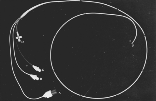
FIGURE 4-1. Quadruple-lumen pulmonary artery catheter. A: Connection to thermodilution cardiac output computer. B: Connection to distal lumen. C: Connection to proximal lumen. D: Stopcock connected to balloon at the catheter tip for balloon inflation. E: Thermistor. F: Balloon. Note that the catheter is marked in 10-cm increments.
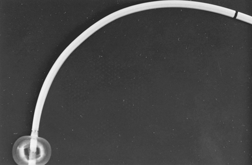
FIGURE 4-2. Balloon properly inflated at the tip of a pulmonary artery catheter. Note that the balloon shields the catheter tip and prevents it from irritating cardiac chambers on its passage to the pulmonary artery.
Insert a central venous cannula or needle into the vein as described in Chapter 2. Using the Seldinger technique, thread the guidewire contained in the catheter kit into the vein and remove the catheter or needle (Figs. 4-3 and 4-4).
Make a small incision with a scalpel to enlarge the puncture site (Fig. 4-5). While holding the guidewire stationary, thread a vessel dilator-sheath apparatus (the size should be 8 Fr if a 7-Fr catheter is to be used) over the guidewire and advance it into the vessel, using a twisting motion to get through the puncture site (Fig. 4-6). The dilator and sheath should only be advanced until the tip of the sheath is in the vessel—estimated by the original depth of the cannula or needle required to access the vein. At that point, the dilator and guidewire are held stationary and the sheath is advance off the dilator into the vessel. Advancing the dilator further may cause great vessel or cardiac damage.
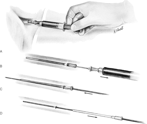
FIGURE 4-3 A: Easy blood aspiration has been demonstrated using the guidewire introducer needle. B: The inner needle is removed. C: The spring guidewire is advanced, soft end first, through the cannula into the vessel. D: With the guidewire held in place, the cannula is withdrawn from the vessel by being pulled over and off the length of the guidewire.
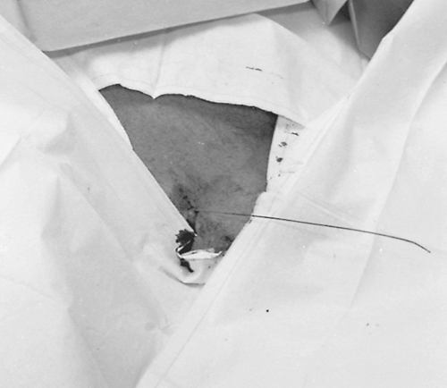
FIGURE 4-4. The spring guidewire, stiff end protruding, is now located in the subclavian vein.
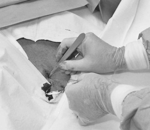
FIGURE 4-5. A small incision is made with a scalpel to enlarge the puncture site.
Remove the guidewire and vessel dilator, leaving the introducer sheath in the vessel (Fig. 4-7). Suture the sheath in place.
Attach stopcocks to the right atrium and PA ports of the PA catheter and fill the proximal and distal catheter lumens with flush solution. Close the stopcocks to keep flush solution within the lumens and to avoid introduction of air into the circulation.
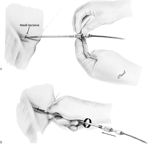
FIGURE 4-6 A: The vessel dilator-sheath apparatus is threaded over the guidewire and advanced into the vessel. B: A twisting motion is used to thread the apparatus into the vessel.
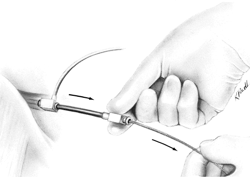
FIGURE 4-7. The guidewire and vessel dilator are removed, leaving the introducer sheath in the vessel.
If a sterile sleeve adapter is to be used, insert the catheter through it and pull the adapter proximally over the catheter to keep it out of the way. Once the catheter is advanced to its desired intravascular location, attach the distal end of the sleeve adapter to the introducer sheath hub.
Pass the catheter through the introducer sheath into the vein (Fig. 4-8). Advance it, using the marks on the catheter shaft indicating 10-cm distances from the tip, until the tip is in the right atrium. This requires advancement of approximately 35 to 40 cm from the left antecubital fossa, 10 to 15 cm from the internal jugular vein, 10 cm from the subclavian vein, and 35 to 40 cm from the femoral vein. A right atrial waveform on the monitor, with appropriate fluctuations accompanying respiratory changes or cough, confirms proper intrathoracic location (Fig. 4-9, center). If desired, obtain right atrial blood for oxygen saturation from the distal port. Flush the distal lumen with heparinized saline and record the right atrial pressures. (Occasionally, it is necessary to inflate the balloon to keep the tip from adhering to the atrial wall during blood aspira-tion.)
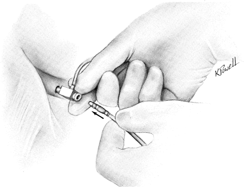
FIGURE 4-8. The catheter is passed through the introducer sheath into the vein.
With the catheter tip in the right atrium, inflate the balloon with the recommended amount of air or carbon dioxide (Fig. 4-9A). Inflation of the balloon should be associated with a slight feeling of resistance—if it is not, suspect balloon rupture and do not attempt further inflation or advancement of the catheter before properly reevaluating balloon integrity. If significant resistance to balloon inflation is encountered, suspect malposition of the catheter in a small vessel; withdraw the catheter and readvance it to a new position. Do not use liquids to inflate the balloon, as they might be irretrievable and could prevent balloon deflation.
With the balloon inflated, advance the catheter until a RV pressure tracing is seen on the monitor (Fig. 4-9, center). Obtain and record RV pressures. Catheter passage into and through the RV is an especially risky time in terms of arrhythmias. Maintaining the balloon inflated in the RV minimizes ventricular irritation (Fig. 4-9B), but it is important to monitor vital signs and ECG throughout the entire insertion procedure. Elevating the head of the bed to 5 degrees and a right tilt position will facilitate the passage of the catheter through the right ventricle and minimize the generation of arrhythmias [59].
Continue advancing the catheter until the diastolic pressure tracing rises above that in the RV (Fig. 4-9, center), indicating PA placement (Fig. 4-9C). If a RV trace still appears after the catheter has been advanced 15 cm beyond the original distance needed to reach the right atrium, suspect curling in the ventricle; deflate the balloon, withdraw it to the right atrium, then reinflate it and try again. Advancement beyond the PA position results in a fall on the pressure tracing from the levels of systolic pressure noted in the RV and PA. When this is noted, record the PAOP (Fig. 4-9, center, D) and deflate the balloon. Phasic PA pressure should reappear on the pressure tracing when the balloon is deflated. If it does not, pull back the catheter with the deflated balloon until the PA tracing appears. With the balloon deflated, blood may be aspirated for oxygen saturation measurement. Watch for intermittent RV tracings indicating slippage of the catheter backward into the ventricle.
Carefully record the balloon inflation volume needed to change the PA pressure tracing to the PAOP tracing. If PAOP is recorded with an inflation volume significantly lower than the manufacturer’s recommended volume, or if subsequent PAOP determinations require decreasing amounts of balloon inflation volume as compared to an initial appropriate amount, the catheter tip has migrated too far peripherally and should be pulled back immediately.
Secure the catheter in the correct PA position by suturing or taping it to the skin to prevent inadvertent advancement. Apply a germicidal agent and dress appropriately.
Order a chest radiograph to confirm catheter position; the catheter tip should appear no more than 3 to 5 cm from the midline. To assess whether peripheral catheter migration has occurred, daily chest radiographs are recommended to supplement pressure monitoring and checks on balloon inflation volumes. An initial cross-table lateral radiograph may be obtained in patients on positive end-expiratory pressure (PEEP) to rule out superior placements.
Special Considerations
In certain disease states (right atrial or RV dilatation, severe pulmonary hypertension, severe tricuspid insufficiency, low CO syndromes), it may be difficult to position a flow-directed catheter properly. These settings may require fluoroscopic guidance to aid in catheter positioning. Infusion of 5 to 10 mL of cold saline through the distal lumen may stiffen the catheter and aid in positioning. Alternatively, a 0.025-cm guidewire 145 cm long may be used to stiffen the catheter when placed through the distal lumen of a 7-Fr PA catheter. This manipulation should be performed only under fluoroscopic guidance by an experienced operator. Rarely, nonflow-directed PA catheters (e.g., Cournand catheters) may be required. Because of their rigidity, these catheters have the potential to perforate the right heart and must be placed only under fluoroscopy by a physician experienced in cardiac catheterization techniques.
Physiologic Data
Measurement of a variety of hemodynamic parameters and oxygen saturations is possible using the PA catheter. A summary of normal values for these parameters is found in Tables 4-3 and 4-4
Pressures
Right Atrium
With the tip of the PA catheter in the right atrium (Fig. 4-9A), the balloon is deflated and a right atrial waveform recorded (Fig. 4-10). Normal resting right atrial pressure is 0 to 6 mm Hg. Two major positive atrial pressure waves, the a wave and v wave, can usually be recorded. On occasion, a third positive wave, the c wave, can also be seen. The a wave is due to atrial contraction and
follows the simultaneously recorded ECG P wave [60]. [61] The a wave peak generally follows the peak of the electrical P wave by approximately 80 milliseconds [62]. The v wave represents the pressure generated by venous filling of the right atrium while the tricuspid valve is closed. The peak of the v wave occurs at the end of ventricular systole when the atrium is maximally filled, corresponding to the point near the end of the T wave on the ECG. The c wave is due to the sudden motion of the atrioventricular valve ring toward the right atrium at the onset of ventricular systole. The c wave follows the a wave by a time equal to the ECG P-R interval. The c wave is more readily visible in cases of P-R prolongation [62]. The x descent follows the c wave and reflects atrial relaxation. The y descent is due to rapid emptying of the atrium after opening of the tricuspid valve. The mean right atrial pressure decreases during inspiration with spontaneous respiration (secondary to a decrease in intrathoracic pressure), whereas the a and v waves and the x and y descents become more prominent. Once a multilumen PA catheter is in position, right atrial blood can be sampled and pressure monitored using the proximal lumen. It should be noted that the pressures obtained via the proximal lumen may not accurately reflect right atrial pressure, due to positioning of the lumen against the atrial wall or within the introducer sheath. The latter problem is more frequently encountered in shorter patients [63].
follows the simultaneously recorded ECG P wave [60]. [61] The a wave peak generally follows the peak of the electrical P wave by approximately 80 milliseconds [62]. The v wave represents the pressure generated by venous filling of the right atrium while the tricuspid valve is closed. The peak of the v wave occurs at the end of ventricular systole when the atrium is maximally filled, corresponding to the point near the end of the T wave on the ECG. The c wave is due to the sudden motion of the atrioventricular valve ring toward the right atrium at the onset of ventricular systole. The c wave follows the a wave by a time equal to the ECG P-R interval. The c wave is more readily visible in cases of P-R prolongation [62]. The x descent follows the c wave and reflects atrial relaxation. The y descent is due to rapid emptying of the atrium after opening of the tricuspid valve. The mean right atrial pressure decreases during inspiration with spontaneous respiration (secondary to a decrease in intrathoracic pressure), whereas the a and v waves and the x and y descents become more prominent. Once a multilumen PA catheter is in position, right atrial blood can be sampled and pressure monitored using the proximal lumen. It should be noted that the pressures obtained via the proximal lumen may not accurately reflect right atrial pressure, due to positioning of the lumen against the atrial wall or within the introducer sheath. The latter problem is more frequently encountered in shorter patients [63].
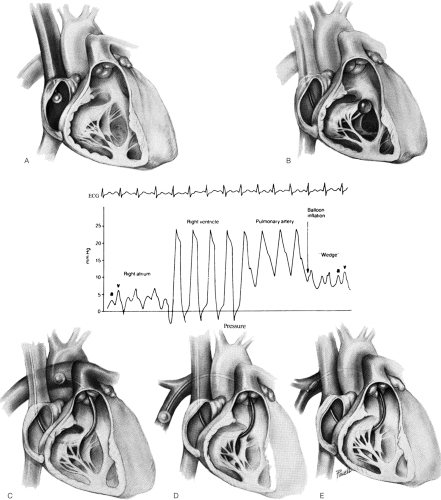 FIGURE 4-9 A: With the catheter tip in the right atrium, the balloon is inflated. B: The catheter is advanced into the right ventricle with the balloon inflated, and right ventricle pressure tracings are obtained. (Center): Waveform tracings generated as the balloon-tipped catheter is advanced through the right heart chambers into the pulmonary artery. [Adapted from Wiedmann HP, Matthay MA, Matthey RA: Cardiovascular pulmonary monitoring in the intensive care unit (Part 1) Chest 85:537;1984, with permission.] C: The catheter is advanced through the pulmonary valve into the pulmonary artery. A rise in diastolic pressure should be noted. D: The catheter is advanced to the pulmonary artery occlusion pressure position. A typical pulmonary artery occlusion pressure tracing should be noted with a and v waves. E: The balloon is deflated. Phasic pulmonary artery pressure should reappear on the monitor. (See text for details.) |
TABLE 4-3. Normal Resting Pressures Obtained during Right Heart Catheterization | ||||||||||||||||||||||||||
|---|---|---|---|---|---|---|---|---|---|---|---|---|---|---|---|---|---|---|---|---|---|---|---|---|---|---|
| ||||||||||||||||||||||||||
TABLE 4-4. Approximate Normal Oxygen Saturation and Content Values | ||||||||||||||||||||||||||||||
|---|---|---|---|---|---|---|---|---|---|---|---|---|---|---|---|---|---|---|---|---|---|---|---|---|---|---|---|---|---|---|
| ||||||||||||||||||||||||||||||
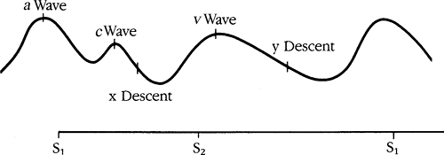 FIGURE 4-10. Stylized representation of a right atrial waveform in relation to heart sounds. (See text for discussion of a, c, and v waves and x and y descents.) S1, first heart sound; S2, second heart sound.
Related posts:Stay updated, free articles. Join our Telegram channel
Full access? Get Clinical Tree
 Get Clinical Tree app for offline access

|


