Chapter 25 Pacemakers and defibrillators
Summary
• Temporary pacing can be achieved in a number of ways; none are ideal.
• The indications for permanent pacemakers and implantable defibrillators are expanding. These devices are becoming increasingly complex.
• Strong sources of electromagnetic interference, diathermy for instance, can interact with pacemakers and defibrillators.
• Consultation with a cardiac electrophysiologist or cardiac technician is essential to understand the detailed functioning of these devices and to plan the treatment of patients.
Basic cardiac electrophysiology
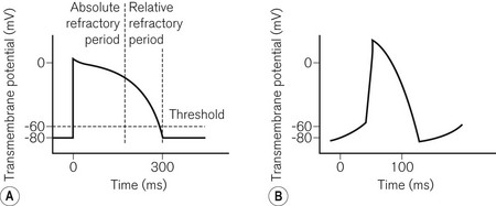
To understand pacemaker and defibrillator functioning, an understanding of normal cardiac electrophysiology is necessary. The myocardium consists of an interconnected network of myocytes. At rest, the myocyte interior is maintained at a negative potential (−80 mV) in relation to the extracellular fluid. This is due to the relative impermeability of the plasma membrane, differential intra- and extracellular ion concentrations and active ion transporters. Either because of the spontaneous inward leak of positively charged ions, in the sinus node for example, or because of an external electrical stimulus, the potential difference across the membrane decreases. At a threshold potential (approximately −70 mV in ventricular myocytes) various ion channels become activated producing further ion influx. This leads to myocyte depolarization and the action potential (Fig. 25.1). Calcium influx leads to the release of additional intracellular calcium stores activating the contractile apparatus, a process described as excitation-contraction coupling.
Pacemakers
The NASPE/BPEG code
1. VVI. A single lead is placed in the ventricle, for pacing (VVI) and sensing (VVI). If the ventricular rate is above the minimum set (the base rate), pacing is inhibited (VVI). Otherwise pacing occurs.
2. AAI. A single lead is placed in the atrium. It functions in a similar way to the VVI and is used for sick sinus syndrome where AV nodal conduction is normal.
3. DDD. Leads are present in the atrium and ventricle. Both chambers (hence dual) can be paced (DDD) and sensed (DDD). If activity in either chamber is sensed a pacing stimulus will be inhibited. If no ventricular activity follows atrial activity, ventricular pacing will be triggered (DDD representing the dual responses of inhibition or triggering).
4. VOO/AOO/DOO. These are the simplest pacing modes. No sensing occurs (_O_) and therefore there can be no response to sensing (__O); the chamber(s) is paced at a fixed rate. This mode is used temporarily where the sensing of external noise could lead to the inappropriate inhibition of pacing, e.g. diathermy. It is also known as asynchronous pacing.
5. VDD. Only one lead is used which paces the ventricle (VDD). An electrode further up the lead is positioned in the atrium allowing dual chamber sensing (VDD). This allows physiological pacing, i.e. ventricular activity follows atrial at a physiological PR interval as long as atrial pacing is unnecessary. This mode is uncommon and is used as an alternative to DDD pacing in order to reduce system complexity.
6. The presence of an (R) as the fourth letter denotes a pacemaker able to increase the paced heart rate in response to the patient’s activity (see below, Software).
Pacing terminology
A number of pacing terms require explanation:
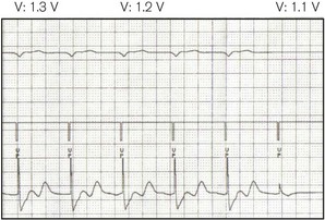
• Threshold (Fig. 25.2) – the minimum stimulus needed to capture the heart. It is given as current (amperes) or voltage (volts) over a time period (pulse width, ms).
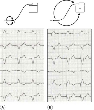
• Unipolar/bipolar – refers to the arrangement (Fig. 25.3) of the negatively charged cathode and the positively charged anode. In the bipolar circuit, the cathode and the anode are separated by a short distance at the pacing lead tip. The circuit is localized to the immediate myocardium. In the unipolar circuit, the cathode is at the pacing lead tip with the anode at a distance; in the permanent pacing system it is found in the pacing box. The unipolar pacing circuit is larger and, therefore, produces a larger pacing artefact on the ECG. While there is little difference between the pacing characteristics of these two conformations, bipolar sensing is less susceptible to external noise.
• Impedance – this represents the total resistance to current flow in the pacing circuit. This resistance occurs in the leads, at the lead–myocardial interface for endocardial leads and in the tissue between the cathode and the anode. Fractures in the leads increase impedance, while insulation breaks reduce it.
Temporary pacing
Transvenous pacing
This is the usual method for temporary pacing. A thin, semi-flexible, shaped, bipolar pacing lead is normally used. The central circulation is accessed via the internal jugular, subclavian or femoral veins, the first of these being preferable as there is a lower risk of complication (e.g. pneumothorax with the subclavian route, infection and deep vein thrombosis with the femoral). Furthermore, with the internal jugular approach, the veins used for permanent pacing are not directly punctured. The lead is manipulated into position at the right ventricular apex under X-ray guidance. Some leads may have a central shapeable stylet to allow more accurate positioning. Others have a tip-mounted flotation balloon to allow non-radiographic positioning. Active fixation (screw tipped) leads are also available to prevent lead displacement. In most cases one ventricular lead is used. Atrial pacing and dual chamber pacing are also possible. For temporary transvenous pacing, due consideration must be given to the possible need for permanent pacemaker insertion and the impact thereon of infection and local complications at vascular access. It is hence advisable to avoid the subclavian route and to use ultrasound guidance for vascular puncture. Various guidelines are listed in the bibliography section at the end of this chapter.
The pacing lead is connected to an external box which allows various programming options:
1. Mode: usually VVI (’demand’) or VOO (‘asynchronous’ or ‘fixed rate’)
2. Output: either the output voltage or current is programmable, the pulse width being fixed. Maximum outputs are higher than with permanent systems as battery size is unrestricted and the threshold is more unstable
3. Sensitivity: the threshold above which electrical activity will be detected as cardiac. This is usually measured in millivolts, a higher value indicating lower sensitivity
4. Rate: usually 30–150 or even higher for the overdrive pacing of tachyarrhythmias.
Transoesophageal and transgastric pacing
An electrode (on a device similar to an oesophageal stethoscope or nasogastric tube),1 placed in the oesophagus, can capture the left atrium, while in the stomach ventricular pacing may be possible. Transoesophageal atrial pacing (TAP) is a simple and safe method for temporary treatment of bradyarrhythmias and is particularly applicable to use during anaesthesia.2 Because voltages of up to 20V or more may be required to achieve capture (Fig. 25.2), a signal amplifier is needed if using an ordinary external (transvenous) pacing box (signal generator). TAP, like transgastric pacing, is rarely used because of unfamiliarity with the technique and scarcity of equipment.
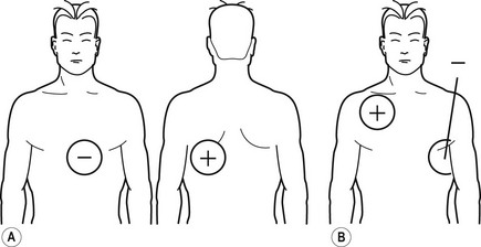
Transcutaneous pacing
In the peri-arrest situation it may be difficult to position a transvenous temporary wire. It is possible to capture the ventricle by passing a large enough current through the chest using specially designed electrodes (Fig. 25.4). These electrodes may also be used for monitoring and defibrillation.


Stay updated, free articles. Join our Telegram channel

Full access? Get Clinical Tree


