Chapter 2 Measurement of pressure and gas flow
Force, pressure and flow
Pressure is force per unit area over which the force acts, i.e.
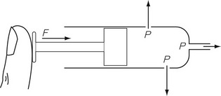
In any gas or liquid, pressure acts in all directions equally, whereas force acts in a given direction. For example, in a full hypodermic syringe, the liquid can be pressurized by applying a force to the plunger of the syringe. This is applied in the direction of travel of the plunger. However, if there were a leak in the barrel of the syringe, the liquid would squirt out sideways from the leak, as well as from the syringe outlet (Fig. 2.1), due to the pressure created by the force acting in all directions within the barrel of the syringe. The amount of pressure generated depends on the area of cross section of the barrel since it is over this area that the force acts. Thus, the pressure generated in a syringe with a small bore is higher than that generated in a syringe with a large bore for the same force applied to the plunger.
All the individual gas laws, i.e. Boyle’s Law, Charles’s Law and Gay Lussac’s Law, can be summarized in the equation below using the Ideal Gas Law which relates the pressure and volume of a given mass of gas to its temperature:

where P is the pressure of the gas, V its volume, T its temperature, R a constant and n the number of moles of gas present. Measuring the change in the number of moles (n) of a gas in a stream gives a measurement of the number of atoms moving in the flow and is called Molar or Mass Flow.
Atmospheric pressure and partial pressure
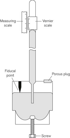
The definition of bar given above shows that the air exerts a pressure called atmospheric pressure. Atmospheric pressure is measured using a barometer, the simplest form of which is the Fortin barometer (Fig. 2.2). This consists of a long transparent tube, sealed at one end, which is filled with mercury and inverted with its open end in a bath of mercury exposed to atmospheric pressure. The atmospheric pressure acting on the surface of the mercury in the bath will support a column of mercury of about 760 mm above the surface of the mercury in the bath, leaving a virtual vacuum between the surface of the mercury in the tube and the sealed tube end. The height of column of mercury is measured using a Vernier scale at the top of the tube, which can be adjusted using a knob next to the barometer tube.
Partial pressure
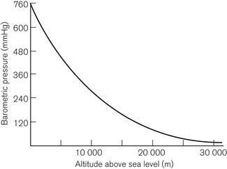
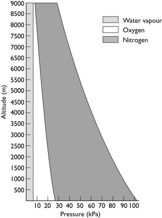
This is Dalton’s Law of Partial Pressures and shows that each gas exerts its own partial pressure independent of its companions. For example, if air is 20% oxygen and 80% nitrogen, then for an atmospheric pressure of 760 mmHg, the partial pressure of oxygen will be 152 mmHg and the partial pressure of nitrogen will be 608 mmHg. However, as Figure 2.3 shows, barometric pressure falls with altitude. Thus, when treating a patient at high altitude, a larger percentage of oxygen is required to supply the same partial pressure of oxygen. It is this partial pressure, not percentage of gas, which is clinically most important. The relationship between altitude and the partial pressure of the components of atmospheric air is shown in Figure 2.4.
Absolute, differential and gauge pressures
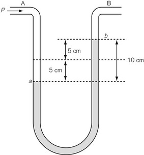
Differential pressure measurement is used where the difference in pressure between two points is required. The simplest differential pressure measurement system is the manometer, as shown in Figure 2.5. This takes the form of a U-shaped tube, partially filled with liquid such as water. Gas at pressure P is applied to end A, with end B open to the atmosphere (so having atmospheric pressure applied to it). The pressure at A causes water to be pushed to the other limb of the U so that the level in the right-hand limb moves to point b above where it was before the pressure was applied, and the water in the left-hand limb is depressed below its original level. If both move by a distance of 5 cm then the difference in water level created is 10 cm, indicating a pressure difference between A and B of 10 cmH2O. Since the end B is open to atmosphere, the pressure at A can be thought of as being above atmospheric and is referred to as gauge pressure and is sometimes denoted by placing a ‘g’ after the pressure unit, e.g 10 cmH2O g. If the ends A and B are at different points within a closed system, such as between the pleural cavity and the alveoli, then the pressure measured is a true differential pressure.
Methods of measuring pressure
Mechanical methods
Bourdon gauge
The Bourdon gauge (Fig. 2.6) is robust, inexpensive and can withstand high pressures. It consists of a curved flattened tube, elliptical in section. When pressure is applied, the tube expands and in doing so attempts to straighten out. Levers, gears or a rack and pinion mechanism translate this movement to a dial pointer. The inlet has a constriction within it to protect the gauge from sudden increases in applied pressure. This gauge is normally used in anaesthesia to indicate cylinder and pipeline pressures. In this application, the pressures measured are much greater than atmospheric pressure. As the response to the applied pressure is determined by the mechanical properties of the Bourdon gauge tube, it effectively measures absolute pressure.
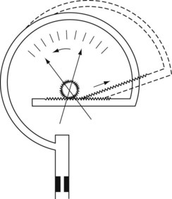
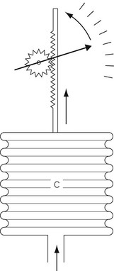
Aneroid gauge
The mechanical principles of an aneroid gauge are shown in Fig. 2.7. It measures absolute pressure and, as with the Bourdon gauge, the movement generated by application of pressure to a chamber is translated into movement of a dial by a mechanical linkage. The amount of movement generated is controlled by the compliance of the aneroid chamber so that the more rigid the chamber the higher the pressure that the gauge will indicate. The sensitivity of the gauge can be controlled by the gearing ratio of the rack and pinion. Where encountered in anaesthetic devices, aneroid gauges are relatively delicate and sensitive but able to indicate low pressures. They may be used to measure airway pressure or blood pressure. If the chamber is sealed and evacuated, the gauge becomes the familiar aneroid barometer. Electronic sensors of pressure have largely superseded the aneroid gauge.
Electronic methods
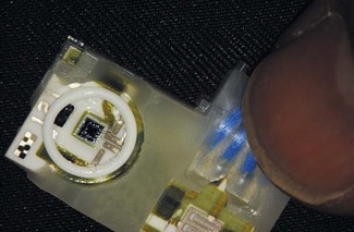
Solid-state electronic pressure transducers
Electronic pressure gauges (transducers) are now the commonest method for the measurement of pressure and (in modified forms) force, in anaesthetic machines and devices such as blood pressure machines or infusion pumps. They can be used for both absolute measurements and differential measurement, depending on how they are housed and mounted. A typical solid-state electronic pressure transducer is shown in Fig. 2.8.


Stay updated, free articles. Join our Telegram channel

Full access? Get Clinical Tree


