CHAPTER 55
Intra-Articular Joint Injections
INTRODUCTION
In the past, the purpose for gaining intra-articular access of joints has been predominant for aspiration of synovial fluid and injection of corticosteroid. Over recent years, other options of intra-articular injections have been emerging, including viscosupplementation as well as biologic therapies such as platelet-rich plasma and stem cell therapy. It is anticipated that many more options will be available in the future and physicians carrying for patients with joint pathologies will want to develop expertise in performing intra-articular injection techniques.
Physicians treating musculoskeletal diseases have been taught an understanding of pathophysiology, functional anatomy, and biomechanics. In addition, physicians need to develop injection experience and a kinesthetic sense of feel as the needle traverses tissue planes and anatomical structures. Physicians who have gained significant fluoroscopic-guided injection experience typically have a much better respect for traversing tissue planes and understanding how a needle behaves when it is guided toward a target. An intra-articular injection is often part of a complex diagnostic and treatment algorithm, and physicians need to have a specific plan as to what will be the next step based on response to the procedure. A patient who benefits for 7 to 14 days may require much more complicated management and planning treatment than the patient who benefits for 6 months after the injection.
Anatomical Landmarks
A key to intra-articular injections is the process of identifying specific anatomical and topographical landmarks. It is recommended to utilize a systematic approach of anatomical landmark localization and skin marking before every procedure. In addition to understanding landmarks, one also needs to have a keen understanding of the anatomy that needs to be avoided during the procedure, such as nerves, vessels, ligaments, tendons, etc.
Selection of needles, medications, and equipments:
• Sterile gloves
• Sterile fenestrated drape
• 4 × 4 gauze soaked with povidone-iodine solution (Betadine)
• 30-gauge 0.5- or 1-in needle for subcutaneous infiltration
• 25-gauge 2-in needle, 25-gauge 3.5-in Quincke needle, 22-gauge 3.5-inch Quincke needle, 22-gauge 5-in Quincke needle
• Quincke needles are styleted, and have a relatively dull tip that does not cut into articular cartilage as readily as a standard sharp beveled needle
• 3-cc syringes
• Hemostat, especially if intra-articular access is for the purpose of aspiration, in order to stabilize the needle to switch syringes.
• Extension tubing to facilitate syringe changes from local anesthetic, to contrast, to injection solution. It also keeps the syringe and hands out of the way of the radiographic picture during fluoroscopic injections.
• Local anesthetic (lidocaine, bupivacaine)
• Proposed injectate (deposteroid, viscosupplement)
• Skin marker
• Radiographic marker for fluoroscopic identification of structures
• Paperclip or similar object for ultrasound identification of structures
Indications
• Symptomatic degenerative shoulder joint disease
• Fluid aspiration for diagnosis and treatment
• Viscosupplementation (not FDA approved)
Contraindications
Contraindications to any intra-articular injection will include:
• Uncooperative or noncompliant patient
• Allergy to previous or proposed medications
• Previous severe steroid flare
• Bacteremia
• Hemarthrosis
• Impending joint replacement surgery within days
• Infectious arthritis
• Joint prosthesis
• Osteochondral fracture
• Periarticular cellulitis
• Poorly controlled diabetes mellitus
• Uncontrolled bleeding or coagulopathy
Relative contraindications include crystalline steroid injections near critical arteries or weight bearing joints. Large crystalline steroids potentially may have mechanical erosive effects with weight-bearing activity immediately following corticosteroid injection and therefore it has been recommended by some to limit weight-bearing activity for a time following a steroid injection.1 It is this author’s preference to use triamcinolone (a smaller particle) rather than Depo-Medrol (a larger particle). Betamethasone may also be an option. Steroids can cause a significant, though transient, increase in blood glucose.2,3 Diabetic patients should therefore be counseled to monitor for hyperglycemia after the procedure.
Preoperative Considerations
• Risk factors for avascular necrosis (AVN)
• Diabetes
• Patients on dialysis
• Hemoglobinopathy
• Previous steroid use
• Cushing’s syndrome
• Radiation exposure
• Hyperglycemia in diabetic patients
• Immune deficiency or elevated risk for potential infection
• Anticoagulation therapy or patients with coagulation disorders
Every physician doing intra-articular injections on a regular basis will eventually have to face the decision as to whether or not one should inject into the intra-articular space of a total joint arthroplasty. The complication of an infection in a total joint arthroplasty can be disastrous, involving removal of the hardware, insertion of devices imbedded with antibiotics, months of antibiotic treatment, and revision of the arthroplasty procedure. However, there may be times when the benefit outweighs the risk and the physician may perform the procedure. One needs to be concerned about the potential activation of latent infections such as Mycobacterium tuberculosis, Nocardia, Cryptococcus, Pneumocystis, Borrelia burgdorferi, toxoplasmosis, etc, when utilizing corticosteroids.
Reducing Pain of Injection
Reduction of the pain of the procedure will also reduce the anxiety and stress in the patient, and can reduce patient concerns and fear of a possible repeat procedure. Simple technical considerations can be made which can substantially reduce pain associated with intra-articular injections, which often require only a slight change in technique or just an extra minute of time. The following are a few brief techniques that can be utilized to reduce the pain of an injection:
• Quick insertion of the needle through skin that has been placed under tension. Depending on the location on the body, skin can have different tensions and texture. On occasion, simply placing a finger or thumb on the skin and stretching the skin taut and quickly (but smoothly) inserting the needle can have a substantial effect on reducing pain.
• The use of topical vapocoolant over the skin can reduce the pain of an injection, there are some questions regarding its sterility. Therefore, weigh the potential risk in a specific patient and specific location before considering a topical vapocoolant.
• Perform a brief sterile skin prep followed by vapocoolant and a subcutaneous injection of 1% buffered lidocaine, and then a complete sterile skin prep prior to the procedure.
• Use buffered lidocaine subcutaneously to provide substantial reduction in the pain. Lidocaine is acidic and has a characteristics sting when injected because of the acidity. Buffering the acidity and creating a neutral pH offers significant reduction in the pain of the injection.
A single dose vial of buffered lidocaine can be made as follows:
• In a 50-cc vial of 1% lidocaine, removed 5 cc from the vial and discard it. Then inject 4.5 cc of 8.4% sodium bicarbonate into the vial. This provides you 49.5 cc of 1% buffered lidocaine.
• Alternatively, in a syringe, mix lidocaine and 8.4% sodium bicarbonate at a ratio of 10:1.
Some more tips to reduce the pain of injection:
• Utilize a 30-gauge 0.5″ or 1″ needle to inject local anesthetic subcutaneously prior to injection. Raise a small skin bleb to reduce the pain of injection and patient anxiety prior to the injection procedure.
• Application of distractive maneuver. Touch, pressure, or skin stimulation in a location away from the site of injection or a simple tissue pinch just prior to needle insertion or at the time of needle insertion can provide a distraction which can reduce pain of a needle insertion.
• Utilization of sedatives. Although IV conscious sedation is rarely indicated for simple intra-articular injections, on occasion the utilization of an anxiolytic prior to injection can reduce anxiety and the pain experienced by anxious patients. Alternatively, consider oral benzodiazepine before the procedure.
Postprocedural Considerations
• Apply gentle pressure with gauze for hemostasis and apply sterile bandage.
• Observe the patient for any signs of syncope, lightheadedness or dizziness immediately following the procedure.
• Perform a passive range of motion to determine subjective response to local anesthetic.
• For weight-bearing joints (hips and knees), support the patient when first standing, to avoid potential collapse from limb weakness.
• Evaluate patient’s symptomatic response of the injection.
• Give patient a pain diary to monitor symptomatic response over the course of 5 to 7 days post injection.
Monitoring of Potential Complications
The patient is to contact the physician if there is any increased skin temperature, erythema, swelling, or signs of infection.
ULTRASOUND-GUIDED JOINT INJECTIONS
Ultrasound-guided interventional procedures are rapidly becoming a popular emerging technology. With imaging resolution improving and the portability of new ultrasound technology as well as elimination of radiation exposure, ultrasound is anticipated to continue to grow in popularity. Images of confirmed initial needle placement as well as post injection position should be saved. Ultrasound-guided injections should be performed with the following basic principles:
• Perform a baseline ultrasound assessment and explore clinical anatomical landmarks for the planned injection.
• The choice of transducer depends on the size of the patient and the depth of the structure. Use 7.5 to 15, higher frequency transducer for shoulder and curvilinear only 3.5 to 7 for obese patients.
• Find the optimal ultrasound window that will allow visualization of the needle at the tissue target. The use of a paperclip (Figure 55-1) or similar localizing device will aid in the rapid identification of the injection site.
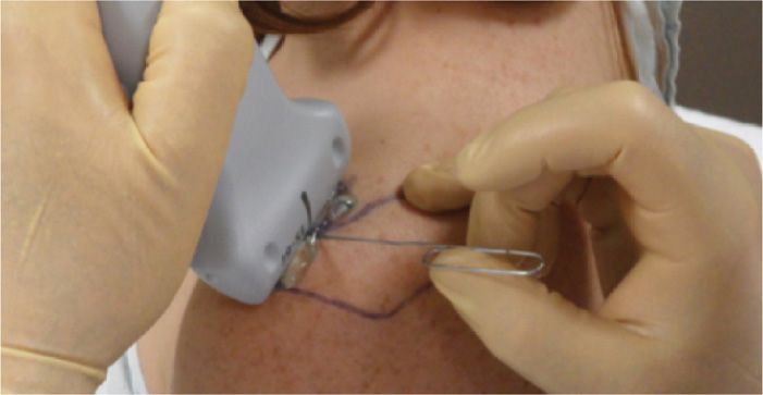
Figure 55-1. Ultrasound marker.
• Create a sterile technique protocol so that the surface of the probe and skin is sterile during the injection procedure.
• Place a thin layer of sterile gel on the skin surface.
• Monitor the progress of needle progression directed toward target site continuously with particular focus on the needle tip.
• Needles typically have to be slightly larger for visualization during ultrasound-guided procedures.
• Visualize the injected solution during and after the injection.
• Save or print visualized image with properly placed needle before and after the injection for purpose of documentation.
There are a few additional steps to maintain sterility when performing ultrasound-guided intra-articular injections. Utilization of ultrasound requires an assistant to maintain sterility. The ultrasound transducer head can be held upright by the cord using an assistant and the physician with sterile gloves can apply a large sterile bio-occlusive dressing (such as Tegaderm) over the transducer head (Figure 55-2A-C). The transducer head is now sterile and can be handled by the physician with sterile gloves. An assistant prior to the procedure can then apply a thin layer of Betadine gel or sterile surgical lubricant (Figure 55-3) over the transducer head. Alternatively, one can use a sterile sleeve and sterile ultrasound gel (Figure 55-4), being sure to place gel on the transducer before placing it in the sleeve, securing it with the supplied sterile rubber bands, and then using sterile gel between the sleeve and the patient.
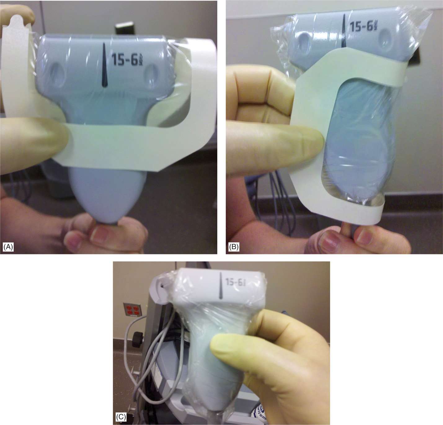
Figure 55-2. Ultrasound probe with bio-occlusive cover (A, B, C).
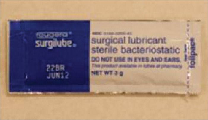
Figure 55-3. Sterile surgical lubricant.
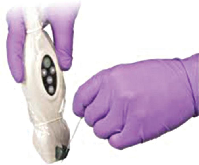
Figure 55-4. Ultrasound sterile sleeve.
INTRA-ARTICULAR INJECTION OF GLENOHUMERAL JOINT
The functional anatomy and biomechanics of the shoulder is complex. There are 4 basic approaches to the intra-articular space of the shoulder discussed in this chapter.
1. Anterior approach
2. Posterior approach
3. Superior approach
4. Lateral approach
The intra-articular injections can be performed by:
• Non-image-guided blind technique
• Fluoroscopy-guided technique
• Ultrasound-guided intra-articular injections
BLIND JOINT INJECTIONS
Disadvantages of blind injections:
• Poor accuracy rates of blind injections, which can be as low as 27% to 42% relying on anatomical landmarks and palpation alone.
• Misplaced injections can result in an intra-tendinous injection (which can lead to tendon weakening), skin depigmentation, soft tissue damage.
• Negative effects on clinical outcome.
Advantages of blind injections:
• Simple and safe injection to perform as an in-office procedure
• No exposure to ionizing radiation
• Reduced expense
Each anatomical approach and method offers advantages and disadvantages. Utilizing image-guided injections obviously offers confirmation of intra-articular placement and resolves some of the inherent inaccuracies of blind procedures. A posterior approach avoids the subclavian artery, subclavian vein, and neural elements of the brachial plexus as well as offers a psychological advantage of the needle being out of the patient’s field of vision. In contrast, the anterior approach offers the advantage of more reproducible bony landmarks such as the coracoid process to help to guide the injection.
Glenohumeral intra-articular injections may be done for the purpose of diagnostic or therapeutic maneuvers. If intra-articular contrast is being injected for the purpose of MRI arthrogram, one needs to consider the approach and avoid a needle traversing through structures that may be of clinical interest. For example, an anterior approach may need to be avoided if one is interested in the subscapularis, glenohumeral ligament or anterior labrum, and it may be more appropriate to utilize a posterior approach in preparation for this particular patient’s MRI.4 If a therapeutic injection is being considered, one may need to consider what imaging may need to be performed after the procedure, since certain types of injections can create abnormal signal on an MRI following an injection, which may interfere in interpretation. Physicians should have knowledge of multiple approaches to the glenohumeral joint to avoid creating an abnormality on MRI in the future or to overcome anatomical variations and body habitus issues.
The technology of ultrasound-guided procedures will probably overcome many of the issues of blind injections and maintain acceptable accuracy rates for intra-articular placement.5–10 Some who defend blind injections will state that clinical experience may play a role in accuracy of intra-articular injections.11 Regardless of a physician’s preference of blind versus image-guided glenohumeral injections, it is important for a physician to possess the skills for blind injection procedures. There can be great variability in the techniques and approaches for glenohumeral joint injections.7, 8 and 12
Relevant anatomy (Figure 55-5):
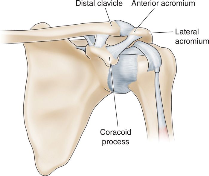
Figure 55-5. Anterior shoulder landmarks (Gray’s anatomy): A = lateral acromiom, B = anterior acromiom, C = distal clavicle, D = coracoid process.
• Humeral head
• Biceps tendon
• Acromion
• Coracoid process
BLIND GLENOHUMERAL INJECTION WITH ANTERIOR APPROACH
There are 2 anterior approaches that will be discussed in this section. The first is the standard anterior approach and the second is the rotator interval approach.
Anterior Schneider Technique
The anterior Schneider technique is one of the most commonly used blind intra-articular glenohumeral joint injection.13 Accuracy of this approach can vary, but in a cadaver study of 50 shoulders, 96% of injections were accurately administered into the glenohumeral joint with only 4% in the surrounding soft tissues and capsule.13–15 This technique is more commonly performed in a supine position, which is the author’s preferred position.
Positioning of the patient:
• Position patient in supine position. Place a small pillow or rolled towel under the elbow to eliminate extension of the shoulder (Figure 55-6).
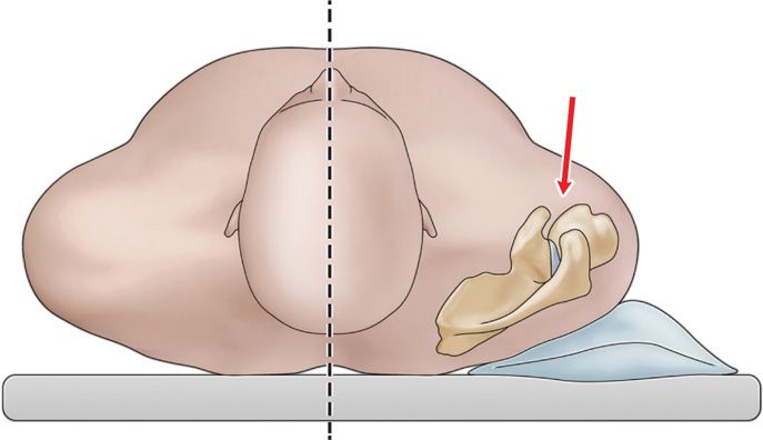
Figure 55-6. Position of patient for anterior approach.
• Externally rotate the humerus to open the joint space and move the biceps tendon further away from the injection site (Figure 55-7).
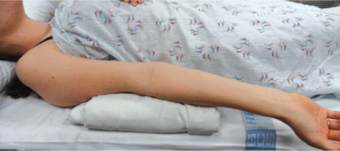
Figure 55-7. Anterior shoulder injection position.
Intraoperative technical steps:
• Carefully palpate the tip of the coracoid process and mark skin for reference. Pressure-mark the skin with a retracted ballpoint pen at a location just below and slightly medial to the coracoid process.
• Sterile skin prep this region and raise a skin bleb utilizing a 30-gauge 1-in needle with 1% buffered lidocaine.
• Attached to spinal needle to a 3-cc syringe filled with 1% buffered lidocaine, and while guiding the needle to the target site, infiltrate local anesthetic sequentially for purpose of loss of resistance technique.
• Advanced the needle in a trajectory that will place the needle tip at the distal humeral head just anterior to the joint line (Figure 55-8). You will experience a distinct fibrous end-feel when you contact the articular capsule overlying the humeral head.
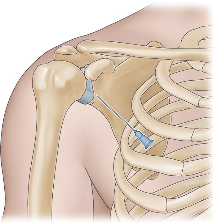
Figure 55-8. Anterior shoulder injection.
• Inject local anesthetic while passing through the thick fibrinous capsule and you will experience a slight loss of resistance when the needle tip traverses the articular capsule and enters the joint space.
Another option is to have the patient sitting with the patient’s hand in the lap and the shoulder muscles relaxed.
• The glenohumeral joint can be palpated by placing the fingers between the coracoid process and the humeral head.
• As the shoulder is internally rotated, the humeral head can be felt turning inward and the joint space can be felt as a groove just lateral to the coracoid process (Figure 55-9).
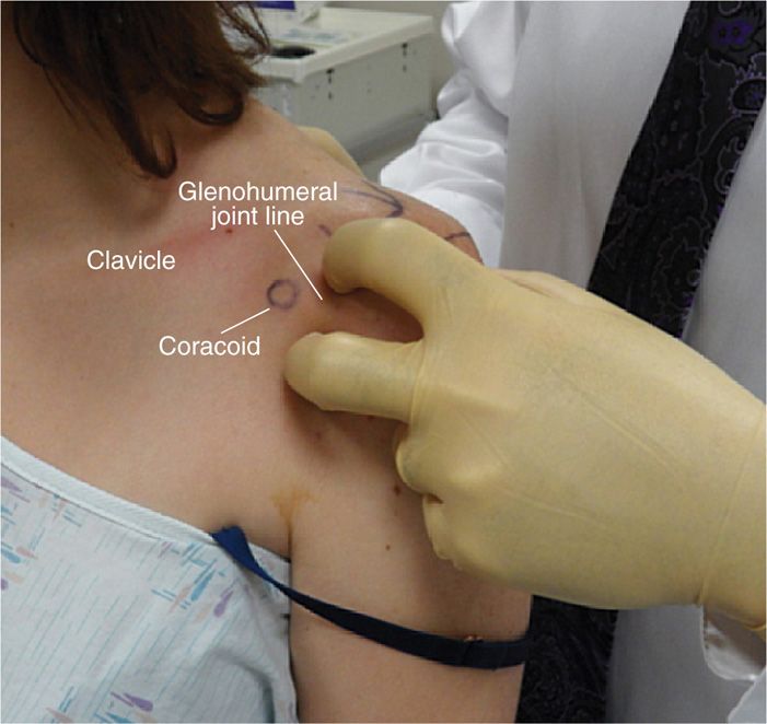
Figure 55-9. Anterior glenohumeral examination.
• Position the patient with the humerus slightly externally rotated to open the joint space.
• Skin mark the coracoid process and sterilely prep the anterior shoulder region.
• Raise a skin bleb of 1% buffered lidocaine just lateral to the coracoid process. Remember that the coracoacromial artery lies medial to the coracoid.
• The needle is directed in a posterior direction, slightly medial. Infiltrate local anesthetic as the needle is advanced into the fibrous capsule.
• Once loss of resistance is experienced after traversing the articular capsule, the needle tip will be within the intra-articular space of the shoulder.
• It is helpful to direct the needle slightly superior as well to avoid the neurovascular bundle.
Clinical Pearl
• This technique is helpful for heavier patients. With the contralateral sterile glove hand, place one finger above the insertion site and one finger below the insertion site and feel for the joint line and the humeral head. Guiding the needle toward the humeral head is then facilitated and avoids the needle contacting the glenoid labrum.
The Rotator Interval Method
A modified anterior approach is through the rotator cuff interval, which is a thick, dense triangular space found between the supraspinatus and subscapularis tendons (Figure 55-10).16 The needle is advanced to the medial upper quadrant of the humeral head, which avoids penetration of the subscapularis tendon and traversing important structures such as the glenohumeral ligaments and labrum, which may be of interest on MRI arthrogram if the injection is being done for that purpose. It may interfere with imaging findings if the coracohumeral ligament and rotator cuff interval are in question. Therefore, one needs to consider any potential imaging and the structures that will be of interest following the injection. This technique can be done in a supine or sitting position. We will describe this method in a supine position. This technique is used to avoid key structures such as the subscapularis, glenohumeral ligaments, glenoid labrum.
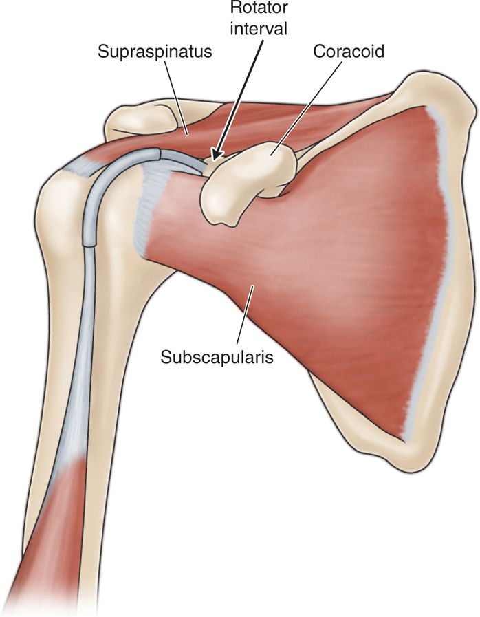
Figure 55-10. Rotator interval approach.
Relevant anatomy:
• Coracoid process
• Sulcus between humeral head and coracoid
Positioning of the patient:
• Patient is positioned supine with the arm externally rotated to open up the joint space and move the biceps tendon further away from the needle insertion.
Intraoperative technical steps:
• Palpate the coracoid process and mark the skin site.
• Palpate between the humeral head and the coracoid process (Figure 55-9).
• Mark the region just lateral to the coracoid process and leave a skin impression with the tip of a retracted ballpoint pen.
• Sterile prep this insertion site and perform subcutaneous local anesthetic injection with 1% buffered lidocaine via a 30-gauge needle.
• A 3-cc syringe filled with 1% buffered lidocaine on a 25-gauge 2-in spinal needle (or other needle of choice) is guided from the point just lateral to the coracoid process posterior and slightly medial as well as 5 to 10 degrees cephalad.
• Infiltrate local anesthetic as the needle is advanced into the fibrous capsule. Once loss of resistance is experienced after traversing the articular capsule, the needle tip will be within the intra-articular space of the shoulder.
• Inject local anesthetic and deposteroid.
Clinical Pearls and Pitfalls
• This technique provides a means to perform an intra-articular injection without penetrating important anatomical structures such as to glenohumeral ligament, subscapularis, and avoiding the glenoid labrum.
• This is a popular technique with radiologists performing gadolinium injections prior to MRI for purpose of MRI arthrogram.
Anterior-Superior Approach
This is a rather novel approach that one should be aware of to perform in certain circumstances. Since the needle does enter the superior aspect of the joint, one must keep in mind that the biceps tendon wraps around the humeral head and inserts at the superior glenoid. Utilizing this technique, it has been shown that periodically the needle can pierce the biceps tendon, potentially weakening the tendon.
This technique utilizes the anterior aspect of the acromioclavicular joint as the predominant landmark (Figure 55-11).
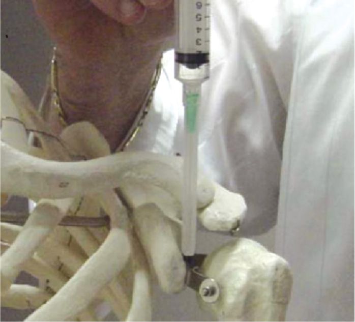
Figure 55-11. Superior approach to the anterior glenohumeral joint.
• Notice the relationship of the anterior margin of the acromion, the anterior margin of the distal clavicle and the tip of the coracoid.
• These structures will provide a slight protuberance palpated under the skin.
• The physician performing the procedure should be well acquainted with topographical anatomy and not confuse the coracoid for the anterior margin of the acromion. This would place the needle into a neurovascular bundle.
• It is helpful to mark the skin at the lateral acromion (A), anterior margin of the acromion (B), anterior distal clavicle (C), and coracoid process (D) to avoid this confusion (Figure 55-12).
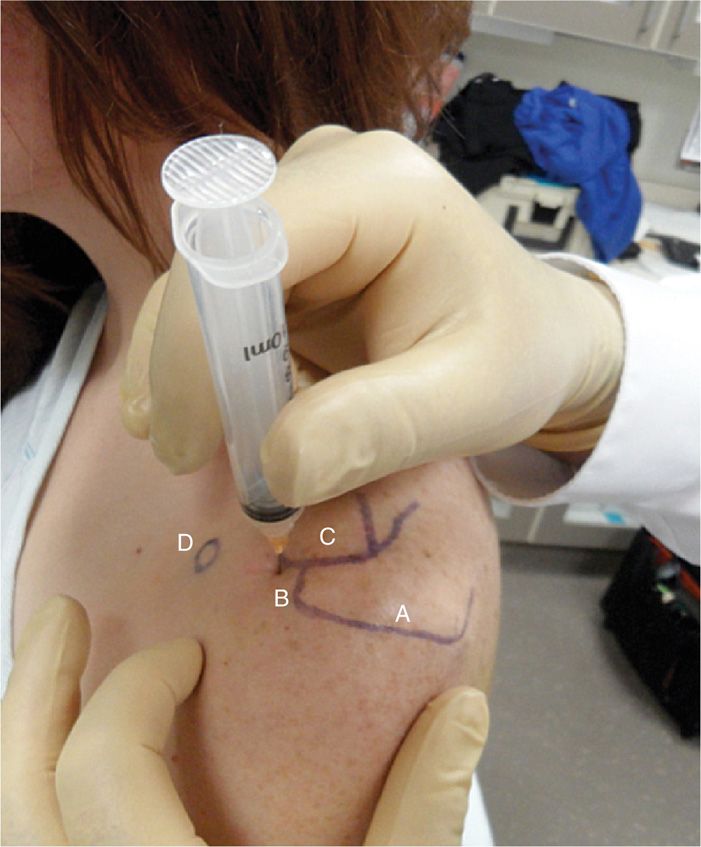
Figure 55-12. Superior approach to the anterior glenohumeral joint.
• This technique provides an alternative access to the glenohumeral joint capsule when an alternative approach may be needed.
Positioning of the patient:
• Place patient in the seated position with the elbow flexed and the arm externally rotated in order to rotate the bicipital tendon away from the traversing needle (Figure 55-13).
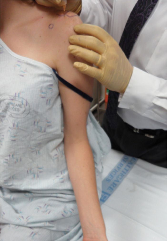
Figure 55-13. Arm positioned with elbow flexed and arm externally rotated.
Selection of needles:
• Use a 25-gauge 2-in needle so that the needle traversing near the biceps tendon is small and, if it inadvertently does pierce the biceps tendon, it causes less damage.
Intraoperative technical steps:
• Palpate and mark the coracoid process, the distal clavicle and the anterior lateral aspect of the acromial process. A skin bleb is raised just anterior to the distal clavicle.
• The arm must be positioned in an externally rotated position to rotate the long head of the biceps tendon away from the needle. It is still possible to traverse the long head tendon at the superior aspect of the joint if one directs the needle to the most superior aspect of the acromion.
• Utilizing a 3-cc syringe filled with 1% lidocaine, infiltrate small amounts of local anesthetic and then slowly advanced the needle sequentially to maintain adequate local anesthesia. After the needle meets the resistance of the fibrous capsule, a slight loss-of-resistance can be felt while injecting the local anesthetic. With the needle in place, gently passively internally and externally rotate the shoulder. If this rotation movement is accompanied by movement of the needle, the tip should be in proper position.17
Clinical Pearls and Pitfalls
• This injection technique has demonstrated issues of inaccuracy when compared to other approaches.
• One of the problems with this approach is that the needle can pierce the biceps tendon as it wraps around over the superior humeral head to attach to the superior labrum damaging the biceps tendon.
BLIND GLENOHUMERAL INJECTION BY POSTERIOR APPROACH
Indications:
• When there is a need to avoid anterior glenohumeral soft tissues and structures for purposes of MRI arthrography or for other medical reasons, a posterior approach offers an excellent option for gaining intra-articular access.
Relevant anatomy:
• Posterior-lateral acromion
• Teres minor muscle
• Infraspinatus muscle
Positioning of the patient:
• The patient is typically placed in a seated position.
• A prone position can also be utilized.
Intraoperative technical steps:
• Identify posterior-lateral edge of the acromion.
• Mark the needle entry zone 3 to 4 cm below the acromion and 2 cm medial to the posterior-lateral margin of the acromion. This point corresponds to the transition between the teres minor muscle and the infraspinatus muscle18 (Figure 55-14).
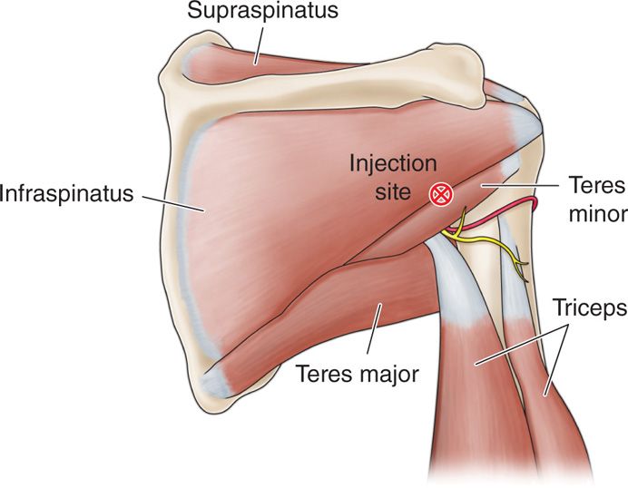
Figure 55-14. Posterior shoulder anatomy: Sup = supraspinatus, Inf = infraspinatus, TMi = teres minor, TMa = teres major, X = injection site.
• Inject a skin bleb with 1% buffered lidocaine utilizing a 30-gauge 0.5-in needle.
• Attach a 3-cc syringe to the spinal needle and hold the needle with a dominant hand; with the nondominant hand anterior to the shoulder, place a finger directly over the coracoid process. The coracoid process and the palpation finger will be a guide to the trajectory of the needle.
• Direct the needle horizontally, being careful not to allow the needle drift cranially or caudally. Guide the needle to the distal humeral head, just lateral to the joint line (Figure 55-15).
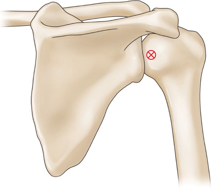
Figure 55-15. Posterior approach to the shoulder.
• Perform sequential infiltration of local anesthetic as needed for patient comfort while advancing the needle. Once the needle comes into contact with the fibrous capsule, perform a slight infiltration of local anesthetic and watch for a slight loss-of-resistance as the needle is advanced further. The needle tip should now be within the intra-articular space of the shoulder (Figure 55-16).
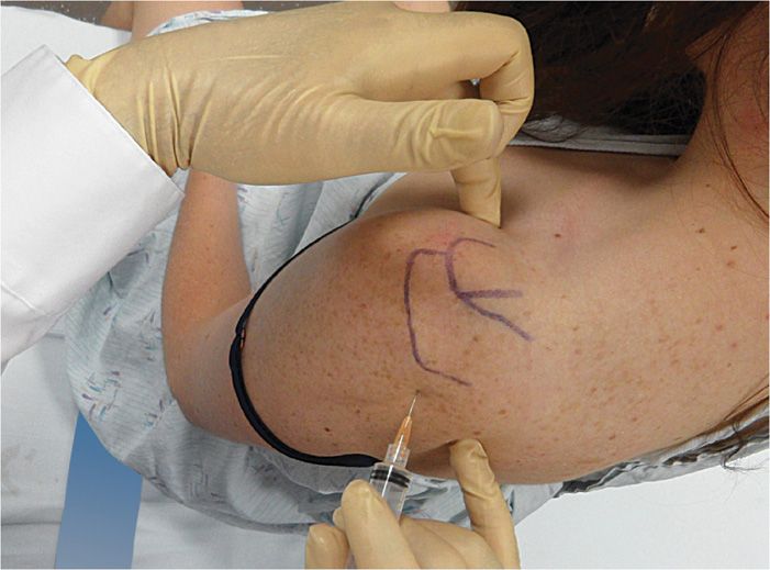
Figure 55-16. Posterior shoulder needle position.
• Aspirate to ensure that the needle had not entered into a vessel and then remove the lidocaine syringe and attach the syringe containing the injectate solution.
FLUOROSCOPIC-GUIDED GLENOHUMERAL INJECTIONS
The main advantage of fluoroscopic-guided glenohumeral joint injection over blind injection is that the needle position can be confirmed and injection of contrast medium can be controlled. For an accurate diagnostic injection, and for those patients with an altered anatomy, fluoroscopic-guided glenohumeral joint injections are important techniques.
Relevant anatomy (Figure 55-17):
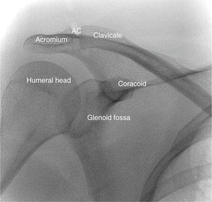
Figure 55-17. Shoulder fluoroscopic landmarks.
• Humeral head
• Coracoid process
• Glenoid and glenoid labrum
Fluoroscopic views:
• Anterior-posterior view tilted parallel to angle of the scapula (25-30 degrees) (Figure 55-18).
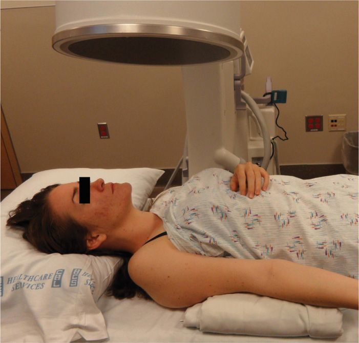
Figure 55-18. Fluoroscopic positioning.
• Patient also can be positioned slightly obliquely to the ipsilateral side with the fluoroscopy unit to remain in a straight posterior-anterior without tilt.
Positioning of the patient:
• Patient is positioned supine on the fluoroscopy table for the anterior approaches and prone for the posterior.
Selection of needles and medications:
• Use a 25-gauge 2-in needle
• Extension tubing to facilitate syringe exchanges from local anesthetic, to contrast, and to injection solution. Extension tubing keeps the syringe and hands out of the way of the radiographic image.
• Nonionic contrast for intra-articular confirmation and documentation of contrast spread.
• Viscosupplementation material (not FDA approved).
Intraoperative technical steps:
• 4 approaches can be utilized
![]() Anterior interval approach
Anterior interval approach
![]() Anterior approach
Anterior approach
![]() Lateral approach
Lateral approach
![]() Posterior approach
Posterior approach
Anterior Approach
• Place radio opaque marker, and mark the skin just inferior to and lateral to the coracoid process under fluoroscopy (Figure 55-19).
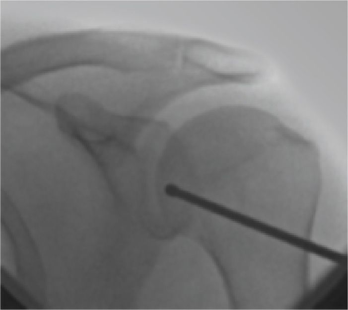
Figure 55-19. Injection site marked.
• After sterile skin prep, perform local anesthetic infiltration.
• Insert spinal needle with extension tubing attached performing sequential local anesthetic injections through the trajectory for patient comfort until contact was made with the fibrous capsule at the distal humeral head.
• The target is the distal humeral head and not the glenoid.
• Avoid trying to put the needle into the joint space between the humeral head and glenoid to avoid potential damage to the glenoid labrum.
• Inject contrast and confirm arthrography (Figure 55-20).
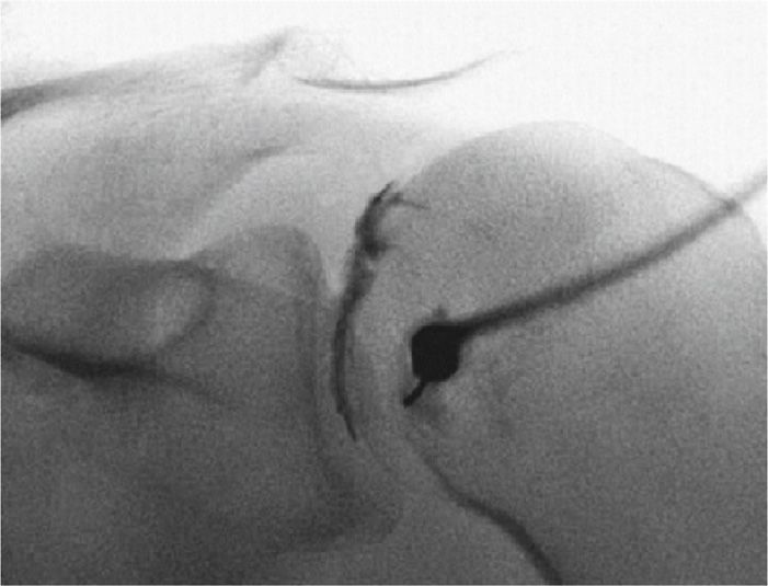
Figure 55-20. Anterior intra-articular injection.
• Save image for documentation.
• Switch syringes and complete injection.
Anterior Interval Approach
• Use similar radiographic positioning over the region 1 cm lateral to the coracoid process, and skin mark this region.
• Sterile prep and drape the skin and inject 1% buffered lidocaine subcutaneously and into deeper tissues.
• Insert Quincke needle attached to the extension tubing, directed toward the distal upper outer quadrant of the humeral head.
• Attached a 3-cc syringe filled with 1% buffered lidocaine and perform sequential local injections as needed through the trajectory until gentle contact was made with the fibrous capsule just over the head of the humerus.
• Inject local anesthetic while passing through the fibrous capsule, performing a loss-of-resistance technique until contact was made with the humeral head. It is helpful to place the bevel against the humeral head.
• Inject contrast and confirm intra-articular placement.
• Save image for documentation.
• Remember that the interval approach avoids the subscapularis tendon, the glenohumeral ligaments, and the glenoid labrum.
Lateral Approach
• Patient is positioned supine, and the lateral aspect of the proximal humerus identified by fluoroscopy.
• Skin entry point is marked at the inferior border of the capsule (at the inferior border of the humeral tuberosity) at the lateral or anterolateral aspect of the humerus (Figure 55-21).
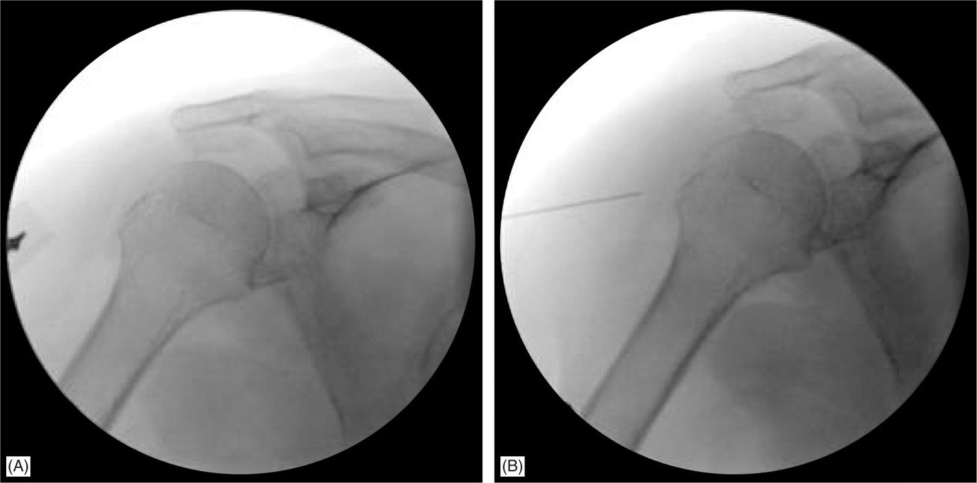
Figure 55-21. Lateral shoulder approach.
• Sterile prep the skin and drape, and inject 1% buffered lidocaine subcutaneously and into deeper tissues.
• Insert Quincke needle attached to the extension tubing and direct toward the proximal outer quadrant of the humeral head.
• Attached a 3-cc syringe filled with 1% buffered lidocaine and perform sequential local injections as needed through the trajectory until gentle contact was made with the fibrous capsule just over the head of the humerus.
• Inject local anesthetic while passing through the fibrous capsule performing a loss-of-resistance technique until contact was made with the humeral head.
• Inject contrast and confirm intra-articular placement (Figure 55-22).
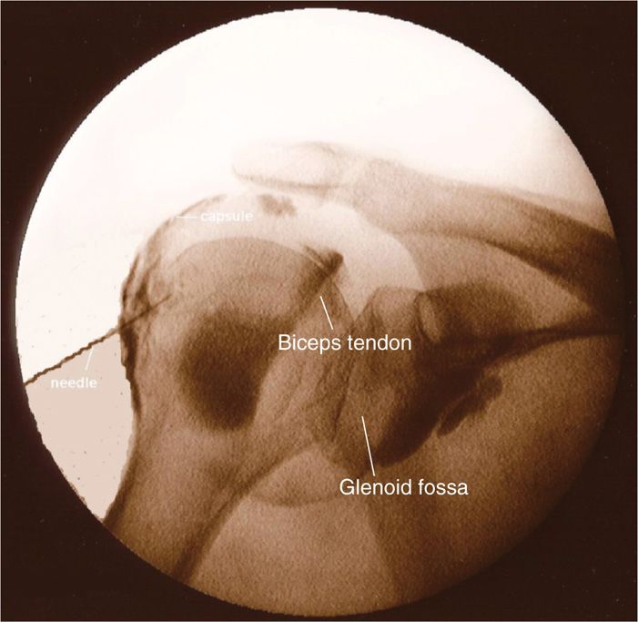
Figure 55-22. Lateral shoulder arthrogram.
• Save image for documentation.
• Capsular adhesions may require large volumes (10-20 cc) of normal saline or very dilute local anesthetic to perform “adhesiolysis” (Figure 55-23).
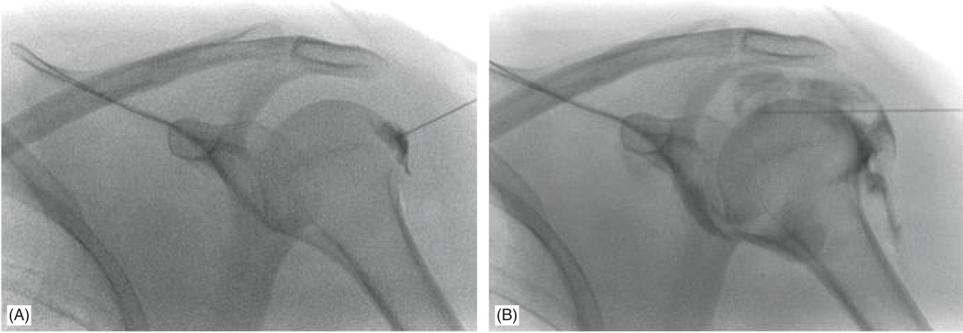
Figure 55-23. Lateral shoulder approach “adhesiolysis.”
Posterior Approach
• The posterior fluroscopic-guided approach requires special prone patient positioning. Once positioning is optimized, a posterior approach utilizing fluoroscopy is a simple procedure. This technique avoids the glenohumeral ligament, subscapularis tendon, and the glenoid labrum.
• Patient will need to be positioned in a oblique posterior-anterior position of approximately 25 degrees (Figure 55-24), a Grashey view,19 or the C-arm will need to be obliqued until the joint line is sharp.
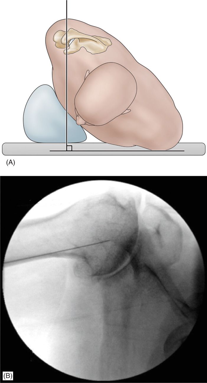
Figure 55-24. Posterior shoulder approach position.
• Externally rotate the humerus to create a laxity of the posterior capsule, which can help with needle placement.
• Once patient is positioned, use radiopaque pointer to target the distal humeral head just lateral to the joint space (Figure 55-25).
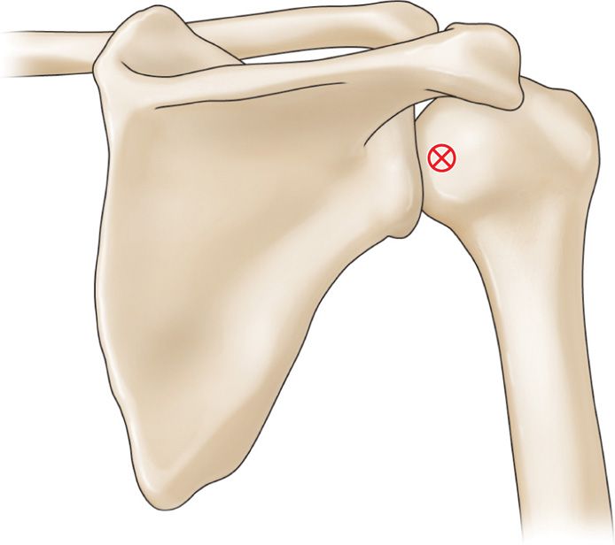
Figure 55-25. Posterior shoulder approach.
• Skin prep and drape this region and perform subcutaneous local anesthesia injection with 1% buffered lidocaine.
• Guide Quincke needle with attached extension tubing to the humeral head similar to what was done with the anterior approaches.
• Perform local anesthesia sequentially through the trajectory for patient comfort and use a loss-of-resistance technique while entering the articular capsule.20
• The target is the humeral head just lateral to the joint line.
• Avoid trying to insert the needle into the joint space between the humeral head and glenoid.
• Inject contrast, confirm intra-articular placement (Figure 55-26).
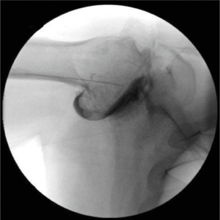
Figure 55-26. Posterior shoulder arthrogram.
• Save image for documentation.
Clinical Pearls
• It is helpful to apply slight downward pressure during the injection of the contrast solution to ensure it is through the posterior capsule and enters the intra-articular space.
• Keep in mind that a true AP view requires obliquing the fluoroscopy unit or tilting the patient.
• Many radiologists prefer a posterior approach because the needle does not traverse important anterior structures that are often of clinical interest in magnetic resonance imaging studies such as the anterior capsule, anterior glenoid labrum, and subscapularis tendon.
• If one suspects posterior labral pathology or pathology in the posterior shoulder, then an anterior approach or a rotator cuff interval approach may be more appropriate if the intra-articular injection is performed for the purpose of MRI arthrogram.
ULTRASOUND-GUIDED ANTERIOR GLENOHUMERAL INJECTION
Studies have demonstrated the efficacy of ultrasound when performing intra-articular glenohumeral injections.6, 21, 22 More recently, ultrasound-guided glenohumeral joint injection was found to be significantly less time consuming and more successful on the first attempt compared to fluoroscopic imaging.23 The ultrasound method described below is a technique initially described by Valls.27
Positioning of the patient:
• Patient positioned in a seated or supine position.
• The author’s preference is to have the patient supine with the head turned and with the arm externally rotated to move the biceps tendon further away from the trajectory of the needle.
Ultrasound transducer:
• An ultrasound transducer 7.5 MHz linear array is typically utilized.
• If the patient is significantly obese, a lower frequency curved ultrasound transducer may need to be utilized to penetrate to deeper tissues.
Relevant anatomy under ultrasound:
• Conduct a brief examination prior to procedure and identify key anatomical structures required for the procedure, which include the coracoid process and the anteromedial portion of the humeral head.
• Transducer head will be positioned transversely as noted in Figure 55-27.
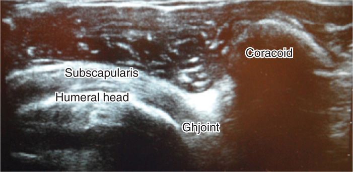
Figure 55-27. Ultrasound of the anterior shoulder.
• The coracoid process will be identified as a hyperechoic structure approximately 1 cm wide protruding anteriorly.
• The medial humeral head will appear as a homogeneous curvilinear or rounded structure with a hyperechoic layer; subchondral bone may show a hypoechoic layer (articular cartilage) (Figure 55-28).
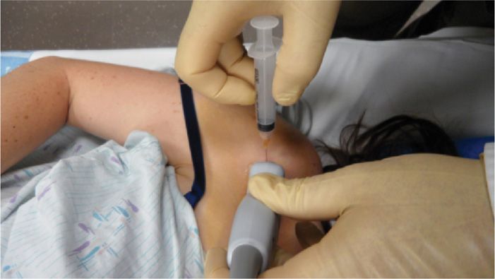
Figure 55-28. Ultrasound probe location.
• Identify the region just lateral to the coracoid process.
• Utilizing a paperclip under the ultrasound head, apply pressure to the skin to mark the needle entry zone (Figure 55-1).
• Wipe the gel off and then sterilely prep and drape this region of the shoulder in preparation for the injection.
Intraoperative technical steps:
• After ultrasound localization of injection site.
• Sterile skin prep and subcutaneous local anesthetic
• A 22-gauge spinal needle attached to extension tubing is directed from the region just lateral of the coracoid to the medial aspect of the humeral head.
• Images should be saved of the initial needle placement as well as postinjection confirmation.
• Remove the needle, clean the skin, apply pressure, then sterile bandage.
Clinical pearls and pitfalls:
• Gentle contact is made on the humeral head just lateral to the joint space with the bevel of the needle toward the bone.
• This provides a way for the bevel to “hug” the articular cartilage and improve injection within the intra-articular space.
ULTRASOUND-GUIDED POSTERIOR GLENOHUMERAL APPROACH
Positioning of the patient:
• Patient can be positioned sitting or prone or lateral decubitus on the contralateral shoulder.
Sonographic transducer:
• 7.5- to 14-MHz linear array transducer is used.
Relevant anatomy under ultrasound:
• Conduct a brief examination prior to procedure and identify key anatomical structures required for the procedure, which include the humeral head and glenoid labrum.
• Position the probe transversely across the joint.
• The humeral head will appear as a curvilinear homogeneous hypoechoic structure (articular cartilage) overlying a hyperechoic layer (cortical bone).
• You should be able to visualize the hyperechoic triangular glenoid labrum found between the humeral head and the glenoid at the joint margin (Figure 55-29).
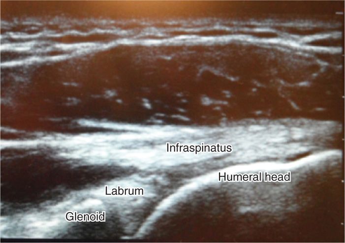
Figure 55-29. Ultrasound of posterior shoulder approach.
• Skin mark the region corresponding to the anterior medial aspect of the humeral head by sliding a paper clip under the transducer head and pressure mark the skin at this region.
• Wipe the gel off and then sterilely prep and drape this region of the shoulder in preparation for the injection.
Intraoperative technical steps:
• Perform subcutaneous local anesthesia with 1% buffered lidocaine over the sterilized prepped area and skin marked previously.
• Direct a 22-gauge needle “in plane” toward the distal humeral head just medial to the joint line.
• Turn the bevel toward the humeral head and allow the bevel to hug the bone.
• With continuous sonographic monitoring, infiltrate the intra-articular space of the humerus.
• Images should be saved of the initial needle placement as well as postinjection confirmation.
• Remove the needle, clean the skin, apply pressure, then sterile bandage.
Clinical pearls and pitfalls:
• This is the favorite approach of most physicians, since it avoids the neurovascular bundle.
INTRA-ARTICULAR INJECTIONS OF THE ACROMIOCLAVICULAR JOINT
• The acromioclavicular joint allows full abduction of the shoulder by acting as a pivot joint. The AC joint may be a source of pain from inflammation, arthritis, or impingement from spurs.
Indication:
• Patients with predominately acromioclavicular joint pain typically describe pain greater with horizontal adduction (cross chest) motions.
• Distal clavicle.
• Acromion.
• Acromioclavicular capsule.
• Coracoclavicular ligament.
• Coracoacromial ligament.
• The angle made by the junction of the distal clavicle and acromion can vary from individual to individual. It is helpful to palpate and identify this angle prior to injection.
• The joint space is slightly wider in the anterior than the posterior, which is helpful when inserting a needle (Figure 55-30).
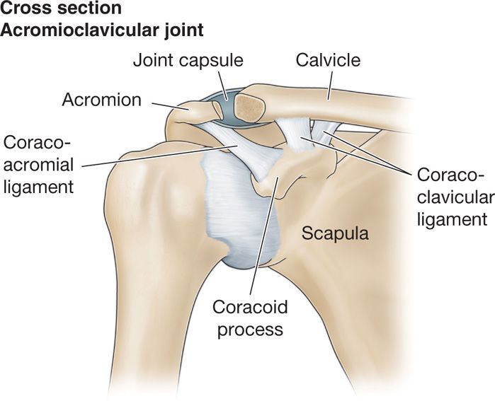
Figure 55-30. Acromioclavicular joint anatomy.
Preoperative considerations:
• Patient with significant osteoarthrosis of the acromioclavicular joint may be at risk for impingement of the rotator cuff tendon (predominantly supraspinatus), secondary to a joint spur extending from the anterior surface of the joint.
BLIND AC JOINT INJECTIONS
Blind AC joint injections require some experienced palpation skills, though the injection can be mastered with practice. If the injections are not placed intra-articularly, patients will not have symptomatic pain relief. It is not helpful to inject steroid over the superior aspect of the joint without entering the intra-articular space.
Positioning of the patient:
• The patient is placed in a seated position.
• It can be helpful for the patient to relax the shoulder and hold a heavy book, object or have an assistant gently distract the humerus downward to open the acromioclavicular joint.
Selection of needles, medications, and equipments:
• The author’s preference is to utilize a 27-gauge 1.5-in needle for this injection, although a 30-gauge 1-in needle can be used on thinner patients.
Intraoperative technical steps:
• With the patient seated, carefully palpate the acromioclavicular joint (Figure 55-31).
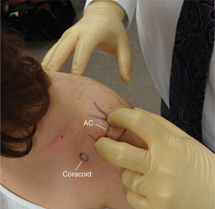
Figure 55-31. Blind acromioclavicular landmarks.
• Mark the skin overlying the exact location of the palpated joint line where the needle will be inserted.
• Inject 1% buffered lidocaine with a 30-gauge 0.25-in needle for local skin anesthesia.
• Direct a 27-gauge 1.5-in or 30-gauge 1-in needle downward and slightly medial into the joint.
Due to the variability in the acromioclavicular joint and a joint with osteoarthritic spurs, the needle may need to be redirected if the needle comes into contact with bone.
Postprocedural considerations:
• Perform passive movements of the patient’s shoulder, especially with horizontal adduction motion, to determine symptomatic response during the anesthetic phase of the injection.
• The subacromial bursa and articular capsule of the acromioclavicular joint can on occasion be contiguous, and therefore injections into the intra-articular acromioclavicular joint space can infiltrate into the subacromial bursa. This can confuse the diagnosis if the physician is unaware of this relationship.
• In patients with hypertrophic changes and osteoarthritis, it is sometimes helpful to do some local anesthetic injections over the superior aspect of the joint so that, in the event that bone was contacted and the needle had to be redirected, the patient will not experience significant discomfort.
FLUOROSCOPIC-GUIDED AC JOINT INJECTIONS
Those who are skilled to perform blind AC joint injection will find it very simple to do fluoroscopically guided AC joint injections. Patients who are quite obese can be a challenge, and fluoroscopy offers a quick and simple injection, which requires less manipulation of the needle, thus reducing pain and patient anxiety with the procedure.
Relevant anatomy:
• Acromion
• Clavicle
• Coracoid process
• Humeral head
Positioning of the patient:
• Typically the patient is placed in a supine position; however, if one does not have a fluoroscopy table, the patient can be positioned seated and the C-arm brought over the joint in a seated position.
• We will describe the procedure in supine position.
Fluoroscopic imaging:
• The angle of the fluoroscopy unit for AC joints will vary based on the joint angle of the patient.
• Typically, it does not require as much tilt as for the glenohumeral joint.
• Thus, start at approximately AP, take a single view and then adjust accordingly (Figure 55-29).
Selection needles and medication:
• Utilize a 27-gauge 1.5-in needle, although a 25-gauge needle for this injection.
• If contrast is to be used for confirmation, then extension tubing will be helpful to make syringe change easier without needle manipulation.
Intraoperative technical steps:
• With a radio-opaque pointer, mark the skin overlying the center of the AC joint (Figure 55-32).
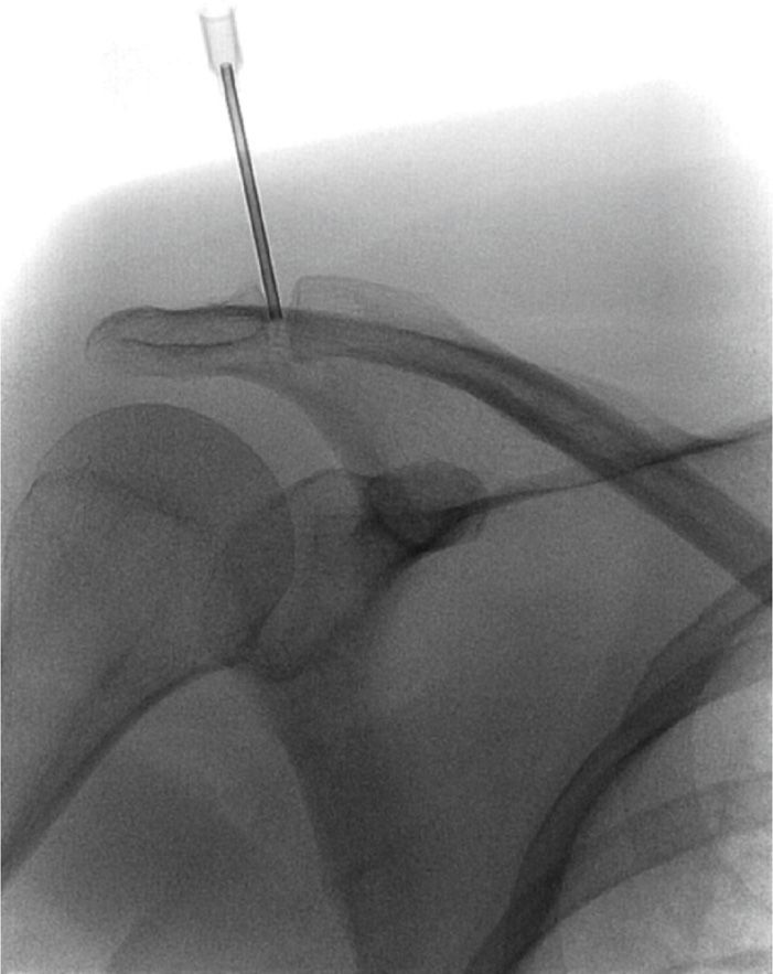
Figure 55-32. Acromioclavicular joint location.
• After a sterile prep and skin anesthesia, the needle is directed into the intra-articular space.
• Contrast can be injected for arthrogram confirmation but only a small volume should be used (Figure 55-33).
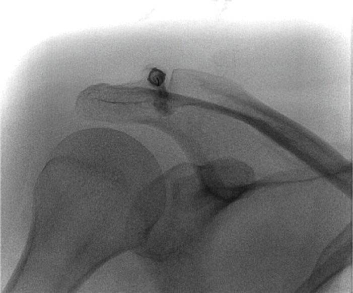
Figure 55-33. Contrast in the acromioclavicular joint.
• Following arthrogram confirmation, switch syringes and complete the injection.
Clinical pearls and pitfalls:
• Remember that the AC joint orientation varies widely and the fluoroscopic view therefore must be individualized.
• Use of an x-ray marker will greatly speed up the procedure by quickly localizing the skin insertion site.
ULTRASOUND-GUIDED AC JOINT INJECTION
Positioning of the patient:
• Patient can be positioned sitting or supine.
Sonographic transducer:
• A 7.5- to 14-MHz liner array ultrasound transducer is used with this injection.
Relevant anatomy under ultrasound:
• Conduct a brief examination prior to procedure and identify key anatomical structures required for the procedure, which include the joint itself, the clavicle, and the acromion.
• With the patient sitting, arm at the patient’s side, the acromioclavicular joint is evaluated in both the sagittal and coronal planes.
• In the coronal position, the clavicle will often sit slightly higher than the acromion.
• Move the transducer slowly anterior to posterior to examine the joint and the joint space (Figure 55-34). You will notice that the joint space is often wider in the anterior aspect.
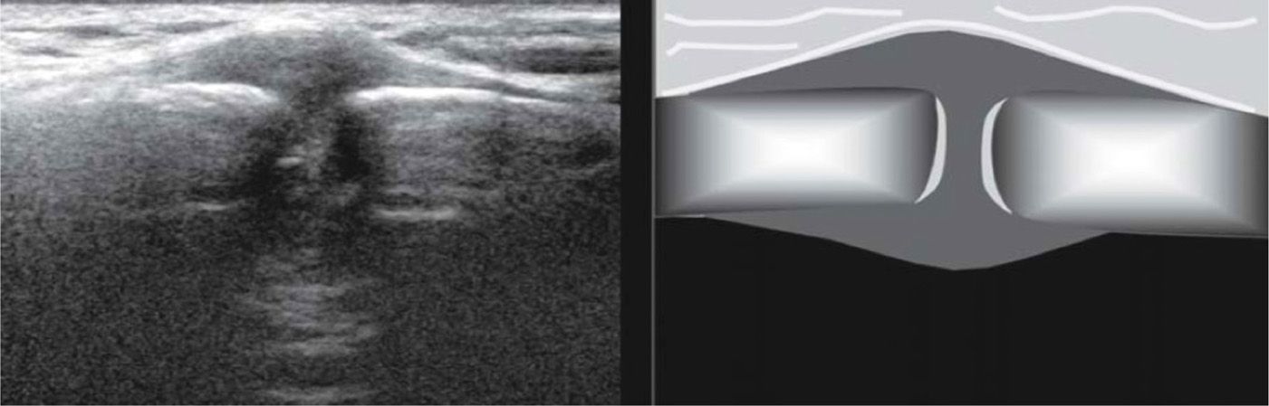
Figure 55-34. Acromioclavicular joint under ultrasound.
• Once the joint space is identified, there are 2 ways to accomplish the injection.
• One is to simply identify the exact location of the joint on the surface of the skin with ultrasound and then do the injection without guidance (“ultrasound localization”).
• The alternate technique is to guide the needle into the joint under continuous ultrasound observation (“ultrasound guidance”).
• The transducer is placed midline over the joint when doing diagnostic ultrasound, but, when performing an ultrasound-guided injection, the transducer head must be positioned medially, placing the transducer head over the lateral aspect of the joint if you plan to do an “in plane” injection.
• Utilizing a paperclip under the ultrasound head, apply pressure to the skin to mark the needle entry zone.
Intraoperative technical steps:
• A 27-gauge needle is directed in the transverse position or “out of plane.”
• The needle is more difficult to track when “out of plane” because the needle is not guided until the needle tip become visible under the ultrasound head.
• In-plane injections can be done but one has to slide the ultrasound head all the way over to the right or left and attempt to track the needle toward the joint.
• Another option is to track the needle down to the distal clavicle, which typically is slightly higher than the acromion, and, once the distal edge of the clavicle is contacted, remove the ultrasound head, tip the needle and syringe upright and then insert the needle into the intra-articular space.
• Images should be saved of the initial needle placement as well as postinjection confirmation.
• Remove the needle, clean the skin, apply pressure, then sterile bandage.
Clinical pearls and pitfalls:
• It is typically more efficient to do ultrasound localization (ultrasound assisted) rather than ultrasound guidance.
INTRA-ARTICULAR INJECTIONS OF HIP JOINT
The techniques of intra-articular injections of the hip are rather simple, since the articular capsule extends over the head of the femur and onto the neck, which makes it relatively simple to place the needle tip into the capsule. In this section, we will cover techniques for blind intra-articular injection as well as fluoroscopy and ultrasound-guided hip injection.
Indications:
• Symptomatic degenerative hip joint disease
• Fluid drainage for diagnosis and treatment
• Viscosupplementation
Relevant anatomy (Figure 55-35):
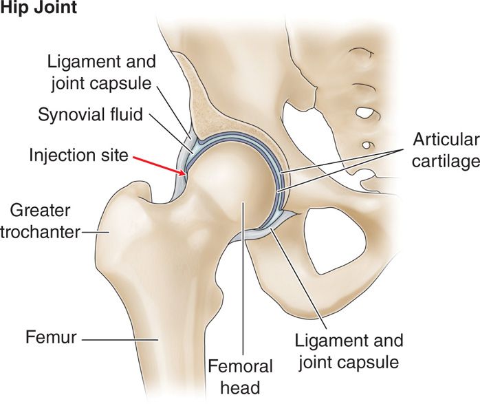
Figure 55-35. Hip anatomy.
• Femoral head
• Acetabulum
• Greater trochanter
BLIND INTRA-ARTICULAR HIP INJECTIONS
These injections have recently come under research scrutiny.9, 24 Kurup reported that utilizing anatomical landmarks resulted in a success rate with blind injections of only 65.1%. Based on this result, he suggested that hip injection should be carried out by a trained specialist under radiologic guidance.1 Ziv et al reported an overall success rate in 40 cadavers of 77.5%. He also indicated that in all 9 unsuccessful injections, the dye typically was located distal to the joint along the lateral aspect of the femoral neck. He did not find any dye from the injections located near neurovascular structures. Based on this, he concluded the accuracy of blind hip joint injections were similar to blind knee injections and therefore could be used safely in the standard office setting. The decision to accept the potential error rate of a blind intra-articular injection is a clinical decision that will have to be made based on the merits of a particular case. There may be circumstances where a blind intra-articular injection would be appropriate and other times when it would not. Blind intra-articular injection should not be utilized when the injections are performed as diagnostic. It is inappropriate to consider placement of a viscosupplementation injection into the intra-articular space of the hip joint without image-guided confirmation.
Relevant anatomy:
• Lateral aspect of greater trochanter.
• Superior aspect of greater trochanter.
Positioning os patient:
• Although the patient can be placed in the supine position, it is the author’s preference to use a lateral position. The patient is placed on the contralateral hip with the knee slightly flexed. However, the supine position may be more appropriate for bilateral positions, to avoid repositioning and re-prepping.
Selection of needles:
• A 3.5- to 5-in Quincke needle is used.
Intraoperative technical steps:
• Palpate and mark the superior aspect of the greater trochanter as well as 2 cm above the superior aspect of the greater trochanter.
• Prep and drape the superior aspect of greater trochanter.
• 1% buffered lidocaine injected subcutaneously 2 cm above the superior aspect of the greater trochanter. Local anesthetic can also be injected into deeper tissues along the proposed trajectory of the needle.
• Position the needle perpendicular to the skin and directed the needle perpendicular to the skin surface or slightly inferior. Exercise caution not to apply pressure on the needle that would cause the needle to curve or skive off course (Figures 55-36 and 55-37).
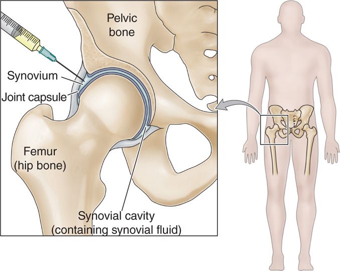
Figure 55-36. Blind hip injection.
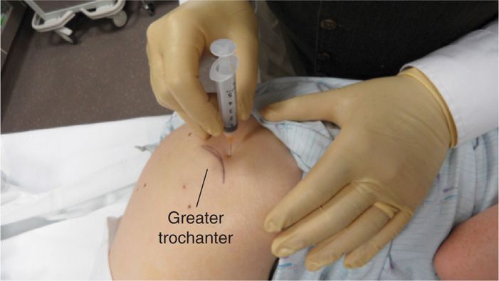
Figure 55-37. Blind hip injection
• Carefully feel for a fibrous end feel at the needle as the needle tip enters the articular capsule. If a bony end feel is encountered without the feel of the fibrous capsule, withdraw the needle completely and redirect the needle.
• Estimate the patient’s size and the potential depth of the injection. If the needle appears to be traveling too deep for the suspected endpoint, pull the needle back once again and redirect, because more likely the needle has skived off course.
• Do not inject unless you have contacted the fibrous capsule and gently tapped bone.
• Aspirate to reassure that the needle tip is not in a blood vessel, and then inject solution.
• Remove the needle and apply gentle pressure and sterile bandaid.
Clinical pearls and pitfalls:
• You must take into consideration the amount of adipose tissue or soft tissue overlying the greater trochanter when estimating the exact location of the superior aspect of the greater trochanter.
• The most common location for needle malposition is distal to the capsule. If the needle tip is felt to strike bone before one feels the capsule, then withdraw the needle and angle typically slightly more inferiorly; the needle tip should then enter the hip capsule.
FLUOROSCOPY GUIDED INTRA-ARTICULAR HIP INJECTION
Relevant anatomy (Figure 55-38):
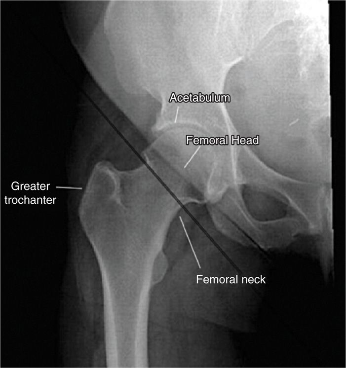
Figure 55-38. Fluoroscopic hip structures.
• Lateral aspect of greater trochanter
• Superior aspect of greater trochanter
• Acetabulum
• Femoral head
Fluoroscopic views:
• Straight anterior-posterior fluoroscopy view; no tube tilt required
Positioning of the patient:
• Supine position with leg slightly externally rotated.
Selection of the needles and medications:
• Occasionally a 5-in Quincke needle may be needed for the significantly obese patient.
• Nonionic contrast for intra-articular confirmation and documentation of medication spread.
• Viscosupplementation material (not FDA approved).
Intraoperative technical steps:
• Bring the fluoroscopy unit to center over the head of the femur.
• With a radio opaque pointer, confirm the location of the neck of the femur.
• Sterile skin prep and drape.
• 1% buffered lidocaine injected subcutaneously at the location noted below (depending upon technique) as well as inject into deeper tissues through the proposed trajectory of the needle.
• 2 approaches can be utilized: anterior and lateral.
Anterior approach (Figure 55-39):
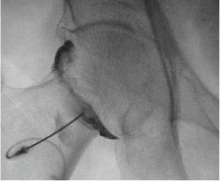
Figure 55-39. Intra-articular hip injection-anterior approach.
• Palpate anterior superior iliac spine and palpate the femoral pulse.
• Mark the region of the skin 2 cm below and 3 cm lateral to the palpated femoral pulse.
• Following local anesthesia, position the spinal needle, directing the needle at an angle of approximately 50 degrees to the skin.
• Advanced the needle directed to the top of the surgical neck below the head of the femur.
• The needle will be advanced through the capsular ligament, encounter a fibrous end feel with the needle tip, and then gently contact os.
• Inject small 1 to 2 cc of contrast for confirmation of position and save image for documentation.
• Switch syringes and inject proposed medication and removed the needle.
Lateral approach (Figure 55-40):
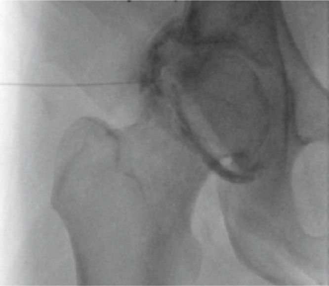
Figure 55-40. Intra-articular hip injection—lateral approach.
• Identify the greater trochanter and the femoral neck by fluoroscopy.
• From the lateral aspect of the thigh, advance the needle to the junction of the acetabulum and femoral neck, using a “loss of resistance” technique with the lidocaine syringe.
• Aspirate to ensure the needle tip is not in a blood vessel.
• Inject small 1 to 2 cc of contrast for confirmation of position and save image for documentation.
• Switch syringes and inject proposed medication and remove the needle.
• Do not attempt to place the needle tip between the acetabulum and the femur head but rather through the fibrous capsule just below the femur head.
• Because of the potential for pseudo-septic reactions if viscosupplementation material is not intra-articular, these injections should usually be performed under fluoroscopy or ultrasound guidance
ULTRASOUND-GUIDED INTRA-ARTICULAR HIP INJECTION
Positioning of the patient:
• Position patient in supine position with hips slightly externally rotated.
Sonographic transducer:
• Consider body habitus and determine whether a higher or lower frequency ultrasound transducer will need to be utilized to maximize visualization of anatomical landmarks.
• A higher frequency 7 to 15 MHz or 6 to 12 MHz linear array transducer can be utilized for visualization of the femoral head.
• It may be necessary to use lower frequencies in order to gain deeper penetration or change the ultrasound head to a 3- to 5-MHz curvilinear array transducer to gain better penetration on heavy patients.
Relevant anatomy under ultrasound:
• Conduct a brief examination prior to procedure and identify key anatomical structures required for the procedure, which include:
![]() Femoral nerve, artery, vein
Femoral nerve, artery, vein
![]() Anterior superior iliac spine (ASIS)
Anterior superior iliac spine (ASIS)
![]() Femoral head
Femoral head
![]() Femoral neck
Femoral neck
![]() Acetabulum
Acetabulum
![]() Acetabular labrum
Acetabular labrum
![]() Iliofemoral ligament
Iliofemoral ligament
• Ultrasound transducer is oriented in the sagittal plane just medial to the ASIS (Figure 55-41).
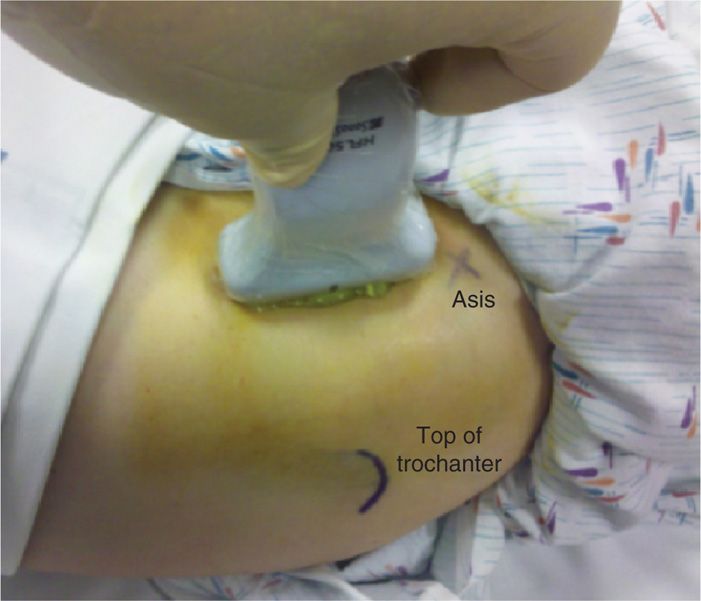
Figure 55-41. Ultrasound transducer for hip injection (head to the right).
• Transducer is moved medial until the hyperechoic, rounded appearance of the femoral head is seen (Figure 55-42).
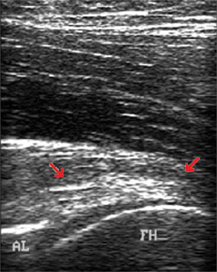
Figure 55-42. Ultrasound of the hip: FH = femoral head.
• Visualize the anterior acetabular labrum.
• Now rotate the transducer into the transverse plane and move transducer medially to identify the femoral nerve and vein. Confirm location of neurovascular structures and then move transducer back over the anterior hip joint in the sagittal plane.
• Rotate the inferior end of the transducer laterally approximately 30 degrees until the femoral neck comes into view.
• Note the hyperechoic iliofemoral ligament and hip capsule as well as overlying hypoechoic articular cartilage over the femoral head.
• Utilizing a paperclip under the ultrasound head, apply pressure to the skin to mark the needle entry zone.
• Wipe the gel off and then sterilely prep and drape this region of the hip in preparation for the injection.
Intraoperative technical steps:
• Maintain a 30-degree position of the transducer in the plane of the femoral neck and place the transducer as far laterally on the head-neck junction as possible.
• Marked the skin at the inferior end of the transducer.
• After ultrasound localization of injection site, sterile prep, and subcutaneous local anesthetic, a 22-gauge spinal needle attached to extension tubing is directed through the previously marked skin in the longitudinal plane of the ultrasound transducer and parallel to the femoral neck.
• Reposition transducer head to visualize the combination of the femoral neck and head as previously imaged.
• Tract the needle to the neck of the femur until the needle tip reaches the fibrous articular capsule and advance through the capsule, entering the intra-articular space (Figure 55-43).
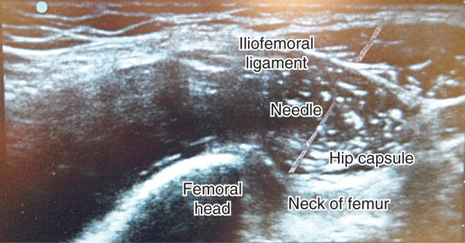
Figure 55-43. Ultrasound hip anatomy and needle.
• Inject local anesthetic (1-2 cc) to confirm intra-articular placement of the needle tip.
• Inject hip with planned injection solution and confirm echoic fluid entering the intra-articular space.
• Images should be saved of the initial needle placement as well as postinjection confirmation.
• Remove the needle, clean the skin, apply pressure, then sterile band-aid.
Clinical pearls and pitfalls:
• Sonographic-guided intra-articular hip injections have been shown to have an accuracy of 96% to 100%.25–27
INTRA-ARTICULAR INJECTIONS OF KNEE JOINTS
The knee joint contains the largest synovial space in the body and in the joint most often injected. There are several approaches to the intra-articular injections have been documented. Arthrocentesis of the knee is easy and relatively painless in a joint that is distended with fluid or when boggy synovial proliferation is present, though it may be much more difficult in joints with severe degenerative changes or distorted anatomy. The non-image-guided blind, fluoroscopy-guided, and ultrasound-guided intra-articular injections of the knee will be discussed below. Each approach and method offers advantages and disadvantages. Utilizing image-guided injections obviously offers confirmation of intra-articular placement and resolves some of the inherent inaccuracies of blind procedures. For most knee injections, the usual point of entry is on the extensor surface, avoiding the large nerves and major vessels that are usually present on the flexor surface. Optimal joint positioning should be accomplished to stretch the capsule and separate the joint ends to produce maximal enlargement and distraction of the joint or synovial cavity to be penetrated.
Indications:
• Symptomatic degenerative knee joint disease
• Synovial fluid aspiration for diagnosis and treatment
• Viscosupplementation
Relevant anatomy (Figure 55-44):
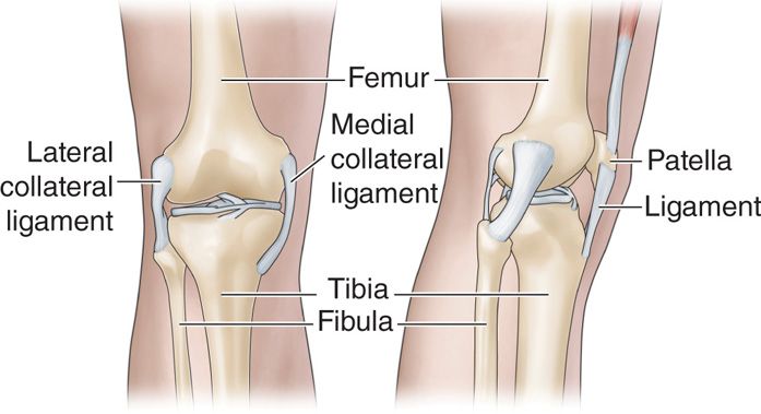
Figure 55-44. Knee anatomy.
• Palpation of knee joint line
• Patellar tubercle
• Patellar tendon
• Inferior pole of patella
Clinical pearls and pitfalls:
• Aspirate and document the volume and character (clear, cloudy, thin, etc) of the synovial fluid
• Viscosupplementation is relatively ineffective in patients with large-volume effusions.28, 29
BLIND INTRA-ARTICULAR INJECTIONS
There are multiple approaches for a blind intra-articular needle placement. Four approaches are common:
• The anteromedial approach
• Anterolateral approach
• Lateral mid-patellar approach
• Medial mid-patellar approach
The highest accuracy is seen in anterolateral and lateral mid-patellar approaches and the lowest is the medial mid-patella approach, which is why this author prefers the anterolateral approach.30 The lateral mid-patella approach has also shown to be quite accurate.31, 32
Confirmation of intra-articular injection can be made by injecting a small amount of air following the injection and then flexing and extending the knee and listening for a “squishy sound” caused by air bubbles within the fluid.
Intraoperative Technical Steps
Suprapatellar Approach
This approach is considered extra-articular because the needle does not enter the joint space directly, but still within the joint space because of the connection between the suprapatellar bursa and the joint space. As a result, fluid can be aspirated and medication injected without direct needle trauma to the articular cartilage. However, it is not an adequate approach for viscosupplementation, because of the high likelihood of extravasation:33
• Patient is placed supine with the knee in full extension.
• Palpate the superior aspect of the patella.
• Mark the skin 1 cm cephalad and 1 cm either medial or lateral of midline.
• Prep and drape the knee and inject subcutaneous 1% buffered lidocaine with a 30-gauge 1-in needle and then inject additional lidocaine in the trajectory of the needle to be used with the procedure.
• Depending on the injection substance, a 27-gauge 1.5-in needle, 25-gauge 1.5-in, or 22-gauge 1.5-in needle can be utilized. Smaller gauge needles can be used for injection and larger gauge needles for aspiration and viscosupplementation.
• If aspiration is to be performed, utilize a hemostat clamp once the needle is in place to stabilize the needle for purpose of switching syringes during the aspiration process.
• Enter the skin approximately 45 degrees from horizontal, aiming caudally and medially toward the middle of the patellar (Figure 55-45).
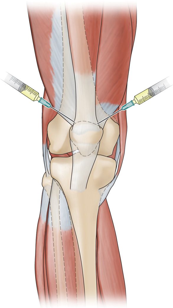
Figure 55-45. Suprapatellar approach knee injection. (From FPnotebook.com.)
Midpatellar Approach
• Patient is placed supine with the knee in full extension.
• Carefully palpate the superior and inferior aspect of the patella and mark the skin 1 cm lateral to the mid patella position.
• Prep and drape the knee and inject subcutaneous 1% buffered lidocaine with a 30-gauge 1-in needle and then inject additional lidocaine in the trajectory of the needle to be used with the procedure.
• Enter the skin obliquely, from a medial or lateral approach, aiming approximately 20 to 30 degrees medially toward the inferior patellar pole.
Infrapatellar Approach (Anteromedial Infrapatellar, Anterolateral Infrapatellar)
• The infrapatellar route is useful when the knee cannot be fully extended or only minimal fluid is present.
• Patient can be sitting or be placed in a supine position with the knee flexed 30 to 40 degrees (Figure 55-46).
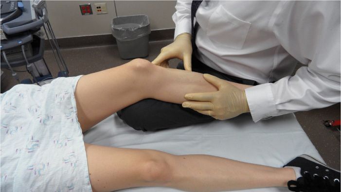
Figure 55-46. Positioning for the infrapatellar approach knee injection.
• The author’s preference is to slide the physician’s flexed knee under the patient’s knee for support and control (Figure 55-46).
• Carefully palpate and identify the injection site lateral or medial and inferior to the patella. Palpate the patella tendon, and then fall off the patella tendon to either the medial or lateral side.
• This depression or dimple is typically the best insertion site.
• Prep and drape the knee and inject subcutaneous 1% buffered lidocaine with a 30-gauge 1-in needle and then inject additional lidocaine in the trajectory of the needle to be used with the procedure.
• Insert a 25- or 27-gauge 1.5-in needle toward the inferior one-third of the patellar pole. Once the needle slides under the patella, the needle tip should be within the intra-articular capsule (Figure 55-47).
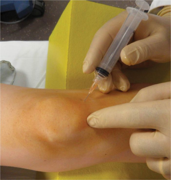
Figure 55-47. Infrapatellar approach knee injection.
• To test for intra-articular placement, inject small amount of local anesthetic. If the patient experiences pain with the injection, this typically signifies that the needle is still within the patellar fat pad. Reposition the needle slightly toward the inferior patellar pole. Once inside the intra-articular space, infiltration of the local anesthetic should not cause pain.
• Aspirate prior to injection. If synovial fluid aspiration is planned, one may want to choose a larger gauge needle for the aspiration procedure rather than the smaller 27- or 25-gauge needle.
Clinical Pearls and Pitfalls
• The most common reason for inaccurate needle placement or extra-articular needle placement is inadvertent injection into the patellar fat pad.
• Because the fat pad is richly innervated, it is painful when injected by any solution. The patient should not feel any pain with the injection. If the patient feels pain with the initial injection, it may be because the needle tip is within the fat pad and not in the intra-articular space.
• Increased pain and “pseudo-septic” reaction experienced by some viscosupplementation injections is caused by inadvertent injection into the patellar fat pad. Avoidance of this almost eliminates this problem.
• If the patient complains of pain, redirect the needle more toward the region just under the inferior patellar pole.
• Once the needle slides slightly under the patella it should reach the intra-articular space.
• Begin reinjecting again and monitor the patient’s subjective response. The initial discomfort the patient reported should resolve and the injection should be able to be carried out painlessly.
• This technique is an excellent way to ensure intra-articular placement of the needle.
FLUOROSCOPY-GUIDED INTRA-ARTICULAR INJECTION OF KNEE
Relevant anatomy:
• Medial and lateral patella femoral condyle
• Medial or lateral patellar facets
• Patellar tendon
• Medial and lateral tibial plateau
• Lateral and medial femoral condyles
Fluoroscopic views:
• Fluoroscopic views can be obtained in both the anterior-posterior as well as lateral views (Figure 55-48), based on preference of the physician and the injection technique utilized.
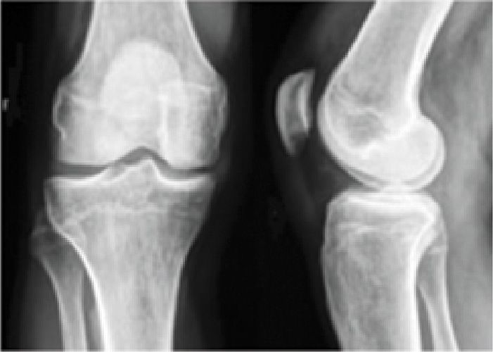
Figure 55-48. Fluoroscopic knee image.
• Some physicians prefer to rotate the image intensifier toward the feet until the joint line is as sharp as possible (Figure 55-49).
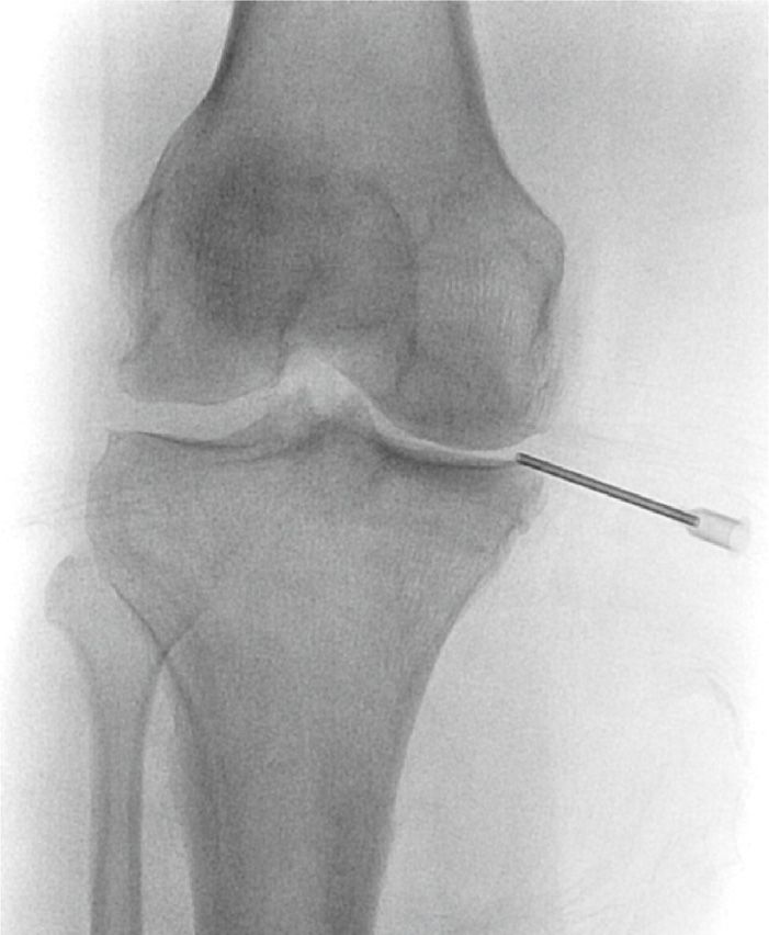
Figure 55-49. Knee joint line optimized.
Positioning of the patient:
• The patient is placed in supine position with a small pillow under the knee to place the knee in slight flexion of approximately 15 degrees (Figure 55-50).
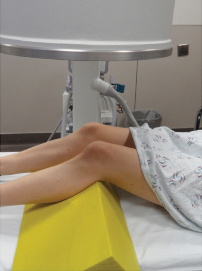
Figure 55-50. Knee support.
Selection of needles and medications:
• A 25-gauge 1.5-in needle can be used; however, some physicians prefer a 23-gauge or 22-gauge needle because it is better visualized under fluoroscopic imaging.
• Nonionic contrast for intra-articular confirmation and documentation of medication spread.
Intraoperative Technical Steps
Anterolateral or Anteromedial Patella Approach
Mark the area one fingerbreadth lateral or medial to the patella. Perform a sterile prep and drape.
Choice of lateral or medial depends on the patient’s greatest area of pain and the size of the joint space. Fluoroscopy allows the delivery of medication to the narrowest of joint spaces (Figure 55-51), which may be therapeutically valuable, especially with the use of viscosupplementation.
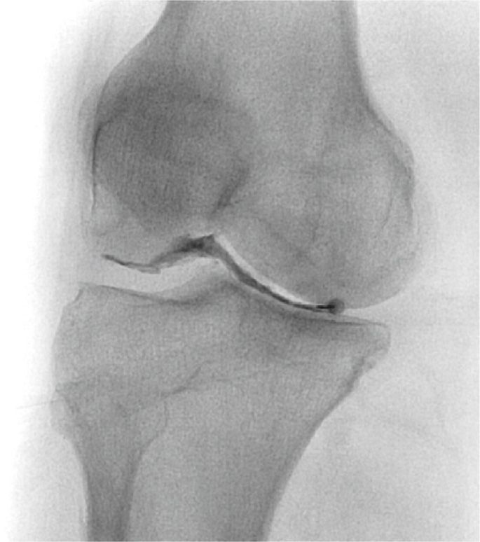
Figure 55-51. Medial joint line narrowing.
Anesthetize the region with 1% lidocaine with a 30-gauge needle.
• The needle is inserted shallowly in the soft tissues and then directed into the joint space.
• With an anterior-posterior view, the needle should be angled approximately 45 degrees medially and 45 degrees inferiorly toward the infrapatellar pole.
• With the rotated view, the needle is directed straight into the joint space.
• Position the fluoroscopy unit for a lateral projection and correct the angle of the trajectory if needed and guide the needle into the intra-articular space.
• The lateral view is not usually needed if a “loss of resistance” with local anesthetic, saline, or air is used.
• Aspirate, and then inject 1 to 2 cc of contrast to confirm intra-articular injection and save image for documentation, which can be done in the anterior-posterior or lateral view.
Clinical Pearls and Pitfalls
• Any of the approaches of intra-articular knee injection can be done with a simple anterior-posterior, a rotated, or a lateral fluoroscopic view with confirmation using nonionic contrast.
• With the current use of ultrasound-guided injections, the exposure to ionizing radiation, and the potential allergic reaction to contrast, fluoroscopic-guided intra-articular injection are beginning to be less attractive.
• However, the contrast may identify capsular disruptions and extra-articular spread of (which would be a contraindication to the use of viscosupplementation medications) or intra-articular adhesions (which would limit the therapeutic spread of medications).
• Neither of these conditions would be identified under ultrasound.
ULTRASOUND-GUIDED INTRA-ARTICULAR INJECTION OF KNEE
Positioning of the patient:
• Patient can be positioned sitting or supine with a pillow under the knees.
Sonographic transducer:
• A 5- to 12-MHz linear transducer is usually used.
Relevant anatomy under ultrasound:
• Conduct a brief examination prior to procedure and identify key anatomical structures required for the procedure:
![]() Femoral condyles
Femoral condyles
![]() Tibial plateau
Tibial plateau
![]() Medical and lateral joint line
Medical and lateral joint line
![]() Infrapatellar fat pad
Infrapatellar fat pad
• Place the ultrasound probe in the transverse plane over the anteromedial aspect of the knee so that the ultrasound transducer head will be positioned at right angles to the needle traversing through the joint from the opposite side (Figure 55-52).
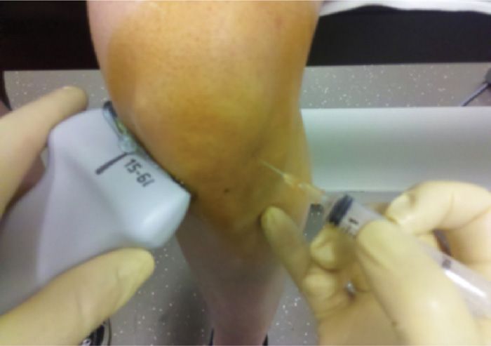
Figure 55-52. Ultrasound positioning for the lateral knee injection.
![]() This will allow image-guided needle trajectory to the point of contact of the femoral condyle.
This will allow image-guided needle trajectory to the point of contact of the femoral condyle.
• Identify the lateral part of the knee similar to that which was described in the blind technique. This represents a small depression or dimple that lies inferior to the patella and lateral to the patellar tendon.
• Skin mark the region corresponding to the joint line by sliding a paper clip under the transducer head and pressure mark the skin at this region
• Wipe the gel off and then sterilely prep and drape this region of the knee in preparation for the injection.
Intraoperative technical steps:
• Inject subcutaneous 1% buffered lidocaine at the site where the needle will be inserted.
• The 22-gauge needle is directed in a slightly upward angle toward the inferior patellar pole and the medial femoral condyle (Figure 55-53).
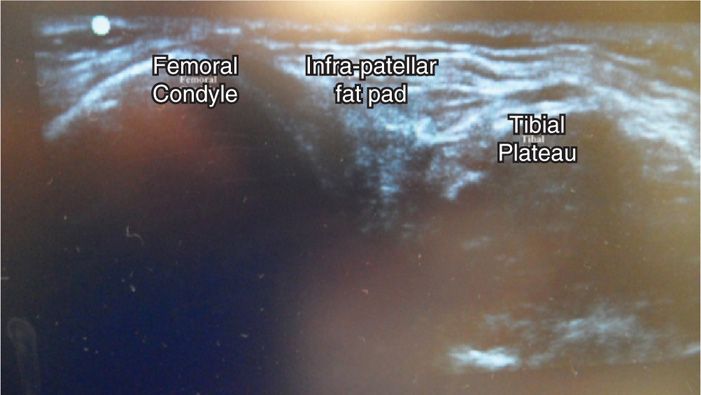
Figure 55-53. Ultrasound knee labeled.
• Gently contact the femoral condyle before performing confirmatory lidocaine injection or performing the therapeutic injection.
• Images should be saved of the initial needle placement as well as postinjection confirmation.
• Remove the needle, clean the skin, apply pressure, then sterile bandage.
Clinical pears and pitfalls:
• Studies have demonstrated that if the needle is not gently in contact with the femoral condyle, there was a 22% failure rate to accomplish the intra-articular injection under ultrasound guidance; therefore, one needs to make sure a gentle contact is made with the medial femoral condyle before injection.34
• The advantage of the technique of using the medial instead of lateral port is that it does not require a sterile preparation of the ultrasound head and gel. This makes the injection quicker and more efficient.
Related posts:


Stay updated, free articles. Join our Telegram channel

Full access? Get Clinical Tree


