Chapter 35 Imaging the chest
RADIOLOGICAL TECHNIQUES
Of the imaging techniques available for investigating patients in the intensive care unit (ICU), the chest radiograph remains the most important, with ultrasound being utilised in a selected group of patients. High-resolution and spiral computed tomography (CT) allow further investigation of these patients in certain situations.
DIGITAL CHEST RADIOLOGY
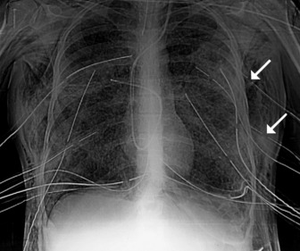
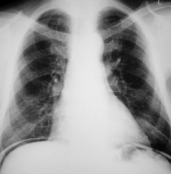
In the ICU, digital chest radiographs may be obtained utilising conventional X-ray generators, but the image is captured on a reusable photostimulable plate instead of conventional film. The digital information is then manipulated, displayed and stored in whatever format is desired. Traditional systems suffer greatly from the large day-to-day variations in the density of the radiograph due to small differences in exposure. Digital radiographic systems are able to capture and display a standard density image from a much wider range of exposures (Figure 35.1).
COMPUTED TOMOGRAPHY
HIGH-RESOLUTION COMPUTED TOMOGRAPHY (HRCT)
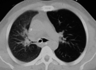
Narrow collimation images of the lung correlate closely with the macroscopic appearances of pathological specimens. In diffuse lung disease, HRCT allows a substantial improvement in diagnostic accuracy compared with chest radiography. Narrow section images can be acquired either as part of a volumetric acquisition or as interspaced images, usually 1.5 mm thickness, obtained every 1 cm. The radiation burden to the patient of this interspace or sequential technique is considerably less than with volumetric scanning – typically by a factor of 10 times.
CLINICAL APPLICATIONS OF HRCT IN THE ICU PATIENT
HRCT in uncomplicated acute respiratory distress syndrome (ARDS):1
HRCT of complications of ARDS2,3
NORMAL RADIOGRAPHIC ANATOMY
THE MEDIASTINUM, CENTRAL AIRWAYS AND HILAR STRUCTURES
Appreciation of abnormality requires a sound grasp of normal radiological anatomy. The mediastinum is delimited by the lungs on either side, the thoracic inlet above, the diaphragm below and the vertebral column posteriorly. Because the various structures that make up the mediastinum are superimposed on each other on the chest radiograph, they cannot be separately identified. Nevertheless, because a chest radiograph is usually the first imaging investigation, it is necessary to have an appreciation of the normal appearances of the mediastinum, together with variations due to the patient’s body habitus and age. Key points include:
THE PULMONARY FISSURES, VESSELS AND BRONCHI
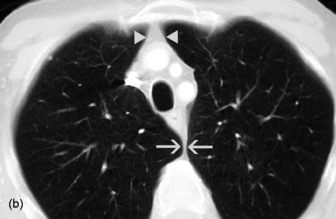
The two lungs are separated by the four layers of pleura behind and in front of the mediastinum. The resulting posterior and anterior junction lines are often visible on chest radiographs as nearly vertical stripes, the posterior junction line lying higher than the anterior. The junction lines are not invariably seen and their presence or absence is not usually of significance (Figure 35.3).
The upper and lower lobes of the left lung are separated by the major (or oblique) fissure. The upper, middle and lower lobes of the right lung are separated by the major fissure and the minor (horizontal or transverse) fissure. The minor fissure is visible in over half of normal PA chest radiographs. The major fissures are not visible on a frontal radiograph and are inconstantly identifiable on lateral radiographs. In a few individuals, fissures are incompletely developed; a point familiar to thoracic surgeons performing a lobectomy, because of incomplete cleavage between lobes. Accessory fissures are occasionally seen.
THE DIAPHRAGM AND THORACIC CAGE
The interface between aerated lung and the hemidiaphragms is sharp and the highest point of each dome is normally medial to the mid-clavicular line. The right dome of the diaphragm is higher than the left by up to 2 cm in the erect position unless the left dome is elevated by air in the stomach (Figure 35.4).
POSITIONING OF TUBES AND LINES4
CENTRAL VENOUS CATHETERS (CVC)
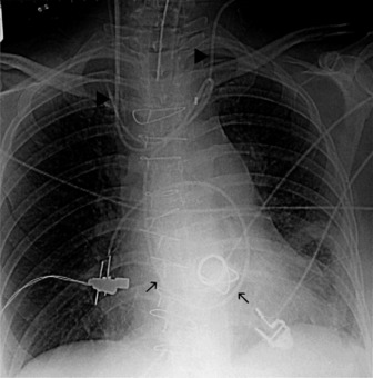
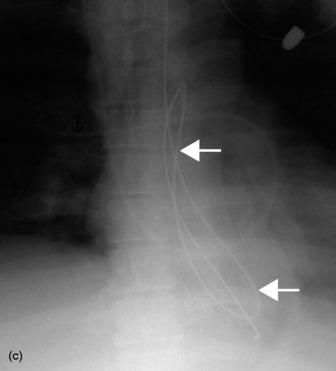
The end of a CVC needs to be intrathoracic, and is ideally in the superior vena cava. CVCs may be introduced via an antecubital, subclavian or jugular vein. Subclavian venous puncture carries a risk of pneumothorax and mediastinal hematoma. Rarely, perforation of the subclavian vein leads to fluid collecting in the mediastinum or pleura. All catheters have a potential risk of coiling, misplacement, knotting and fracture (Figure 35.5). The tip should not abut the vessel wall at an obtuse angle.
PULMONARY ARTERY FLOTATION CATHETERS
Ideally the end of the catheter should be maintained 5–8 cm (2–3 inches) beyond the bifurcation of the main pulmonary artery in either the right or left pulmonary artery (see Figure 35.5). When the pulmonary artery occlusion pressure is measured the balloon is inflated, and the flow of blood carries the catheter tip peripherally, to an occluded position. After the measurement has been made the balloon is deflated and the catheter returns to a central position; otherwise there is a risk of pulmonary infarction. The inflation balloon is radiolucent. The balloon should normally be kept deflated.
NASOGASTRIC TUBES
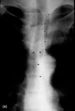
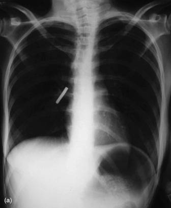
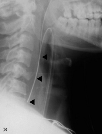
These should reach the stomach but may coil in the oesophagus or occasionally are inserted into the tracheobronchial tree (Figure 35.6).
ENDOTRACHEAL TUBES
Extension and flexion of the neck may make the tip of an endotracheal tube move by as much as 5 cm. With the neck in neutral position the tip of the tube should ideally be about 5–6 cm above the carina. A tube that is inserted too far usually passes into the right bronchus, with the risk of non-ventilation or collapse of the left lung (Figure 35.7).
PLEURAL TUBES
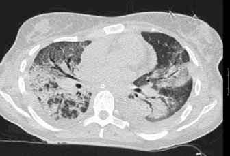
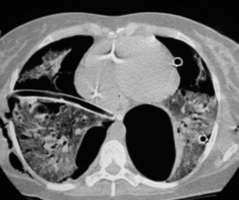
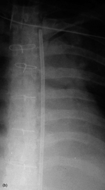
These are used to treat pleural effusions and pneumothoraces. A radiopaque line usually runs along pleural tubes, and is interrupted where there are side holes. It is important to check that all the side holes are within the thorax. Tracks may remain on the chest X-ray following removal of chest tubes, causing tubular or ring shadows. When doubt remains about tube position, then CT scanning should be considered (Figure 35.1 and 35.8).
INTRA-AORTIC BALLOON PUMP
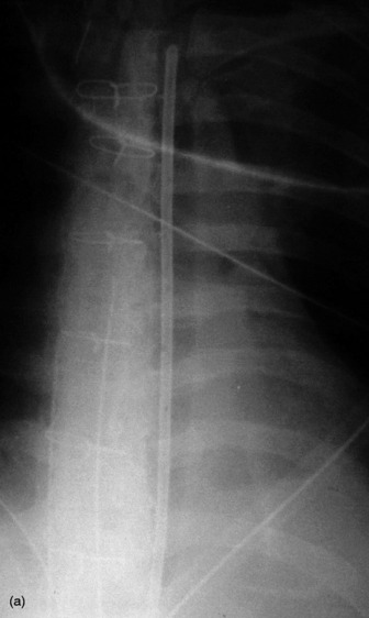
These are used in patients with cardiogenic shock, often following cardiac surgery. The ideal position of the catheter tip is just distal to the origin of the left subclavian artery (Figure 35.9). If the catheter tip is advanced too far it may occlude the left subclavian artery, and if it is too distal the balloon may occlude branches of the abdominal aorta. The intra-aortic balloon pump may only be visible by its radiopaque tip (see Figure 35.5).
< div class='tao-gold-member'>
Stay updated, free articles. Join our Telegram channel

Full access? Get Clinical Tree


