5 Imaging Spinal Cord Injuries Paul D. Campbell Jr. and John A. Carrino In the setting of trauma, imaging of the spine is often of paramount importance. There are 30,000 traumatic spinal injuries each year in the United States.1 The majority of injuries sustained to the spine are a result of motor vehicle accidents. Most patients who have sustained acute injuries to the spine present with pain, and appropriate radiologic examinations are obtained, which are tailored to help make specific diagnoses. The preliminary evaluation often consists of radiographs, but with the widespread availability, increased speed,2,3 and improved sensitivity of computed tomography (CT),4–10 it has become increasingly the initial evaluation of choice. However, radiographs and CT, although quite sensitive in the diagnosis of bony injury, are less sensitive in the detection of soft tissue and spinal cord injury. The pattern of spinal cord injury without radiographic abnormality (SCIWORA) is often encountered and introduces the need for further advanced imaging techniques, such as magnetic resonance imaging (MRI), which are better suited for such evaluation (Table 5.1). Furthermore, the determination of neurologic deficit is often difficult when a patient presents with altered mental status, further complicating the clinical picture. The clinician must integrate the clinical history, mechanism of injury, and physical examination to appropriately tailor diagnostic radiologic evaluations to quickly and effectively obtain diagnoses so that appropriate patient management can be initiated. Spinal cord injury can be divided into the segment of the spine that is injured-cervical, thoracic, or lumbar. Injuries within these portions of the spine can be further subdivided based on the mechanism of injury. This chapter discusses the most common types of injury in these classifications and their radiologic manifestations.
| Radiography | Preliminary Evaluation |
|---|---|
| CT | • Faster, increased sensitivity, widespread availability |
| • More commonly used now for initial evaluation | |
| • More sensitive for osseous than soft tissue abnormalities, can result in spinal cord injury without radiographic abnormality (SCIWORA) | |
| MRI | • Better suited for comprehensive evaluation; sensitive to bone, soft tissue, and spinal cord |
 Cervical Spine
Normal Anatomy and Imaging Modalities
Radiographs
In the initial evaluation of trauma, a standard three-view radiographic series of the cervical spine is often obtained (Table 5.2). This series includes anteroposterior (AP), lateral, and odontoid views. Of these views, the lateral is usually the most helpful. A normal lateral view of the cervical spine is illustrated in Fig. 5.1. There are many important landmarks to recognize on the lateral view, and distortion or absence of any of these is often a clue to the presence of cervical injury. There are five important lines to recognize in the evaluation of the lateral radiograph. The first is the anterior prevertebral soft tissue line. This line is usually curvilinear, with an expected convexity at or about the level of C4-C5 near the origin of the esophagus. The second and third lines, the anterior and posterior vertebral lines, correspond to lines linking the anterior and posterior cortices of continuous vertebral bodies and are curvilinear in a fashion that mimics the usual slight lordosis of the cervical spine. The fourth line is the spinolaminar line, which is also curvilinear and corresponds to the location where the paired laminae meet at the base of the spinous process. The final line, the spinous process line, is another curvilinear line that corresponds to the posterior border of the respective spinous processes.
There are additional structures that should be evaluated in the approach to the lateral cervical spine radiograph. The axis ring is the circular structure that projects over the C2 vertebral body. The junction of the C2 vertebral body and pedicle forms the anterior arc of the axis ring. The junction of the odontoid process and the C2 vertebral body forms the superior arc. The posterior arc corresponds to the posterior cortex of the C2 vertebral body, and the projection of the C2 transverse process forms the inferior apex. Disruption of any portion of the ring is secondary to disruption of the structure that forms that part of the ring and is indicative of an abnormality.
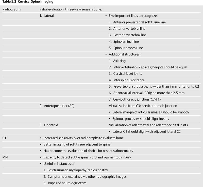
Many other structures should be evaluated on the lateral radiograph. The respective intervertebral disk spaces should be visualized, and their heights should be essentially equal to one another. If there are one or more disk spaces that are decreased in height, this can be secondary to acute or chronic disk disease. On the lateral view, the cervical facet joints are well visualized and should parallel one another. Another space that should be evaluated is the interspinous distance, which is the distance between continuous spinous processes. If one or more of these spaces is abnormally widened with respect to the others, it is often an indicator of cervical spine injury. The prevertebral soft tissues should be thoroughly evaluated. The soft tissues anterior to the upper cervical spine (C4 and above) should be no wider than 7 mm anterior to C2,11 but may be greater inferiorly, with the increased distance anterior to the lower cervical spine due to the interposed esophagus. Another important distance to evaluate is the atlantoaxial interval (ADI), which is the distance between the posterior cortex of the anterior C1 arch and the anterior cortex of the odontoid process. This distance should be no greater than 2.5 mm.11 The cervicothoracic (C7-T1) junction is the final landmark that must be evaluated on the lateral radiograph. If the superior end plate of T1 is not visualized, a swimmer’s view is performed. The swimmer’s view is obtained by positioning the patient with one arm fully abducted over the head and the opposite shoulder slightly depressed in an attempt to visualize the complete cervical spine down to the level of the superior T1 end plate. However, positioning for this view can exacerbate instability in an injured spine, so if there is high clinical suspicion of injury, a CT should be performed instead.
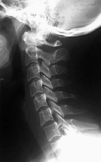
Fig. 5.1 Normal lateral cervical spine radiograph. Note the normal alignment of the anterior prevertebral soft tissue line, anterior and posterior vertebral body lines, spinolaminar line, and spinous process line.
The second view in the cervical spine series is the AP view. The AP view helps evaluate portions of the cervical spine that are not adequately evaluated on the lateral examination. Typically, the AP view permits visualization of the cervical spine from C3 to the cervicothoracic junction. The lateral margins of the articular masses should be smooth. The spinous processes should align in a linear fashion, except when normal variant bifid spinous processes are present, in which alignment is often distorted. On the AP view, the uncovertebral joints are well visualized, and subtle fractures as well as degenerative changes can be visualized.
The final view in the cervical spine series is the odontoid view. The odontoid view permits appropriate visualization of the atlantoaxial and atlanto-occipital joints. The lateral borders of C1 should align with the adjacent lateral margins of C2. The morphology of the odontoid process is visualized well with this view, and odontoid fractures can be detected. The odontoid view is often altered by rotation or head tilt, which narrows the atlantoaxial and atlanto-occipital spaces that occur on the side opposite the head movement.
There are special considerations in the imaging of children primarily because children often exhibit radiographic manifestations of increased ligamentous laxity. The prevertebral soft tissues in children often appear increased in size due to poor positioning caused by ligamentous laxity. Imaging the cervical spine of the child at inspiration with the neck in flexion can prevent the so-called pseudomass in the prevertebral soft tissues. Another radiographic manifestation of ligamentous laxity in children is an increased ADI (up to 5 mm), secondary to laxity of the transverse atlantal ligament. A final manifestation of ligamentous laxity in children is physiologic pseudosubluxation of C2-C3 and C3-C4, manifested by up to 2 mm of subluxation of one vertebral body on another.
Computed Tomography
Computed tomography can identify essentially every bony landmark that is evaluated on the standard radiographic examination (Table 5.2). It has a significantly increased sensitivity over radiographs in the evaluation of bony injury. Furthermore, it has the advantage of better visualization of soft tissue structures adjacent to the spine. For these reasons, in addition to its speed and widespread availability, CT has become the evaluation of choice in the setting of spinal trauma in many institutions. The proliferation of multidetector CT with three-dimensional (3D) reconstruction capability has revolutionized imaging of spinal injury and has further increased the ability to quickly detect sequelae of spinal injury from the craniooccipital to cervicothoracic junctions.
Magnetic Resonance Imaging
Magnetic resonance imaging is particularly helpful in the evaluation of injury to the spinal cord. Although not indicated as the primary evaluation in the setting of spinal trauma, MRI can be a useful adjunct particularly when a patient experiences posttraumatic myelopathy/radiculopathy, when there are symptoms that cannot be explained by other radiographic studies, or when the patient has an impaired sensorium or difficult neurologic examination (Table 5.2). MRI has the capacity to detect even subtle injury to the spinal cord, which is a strength that radiographs and CT lack. MRI also is useful in the detection of ligamentous injury.12
Mechanisms of Injury
There are multiple types of cervical spine injury, which are best classified by the mechanism of injury. The mechanism of injury is described by the vector of the force that causes it. Most patients with cervical spine trauma have more than one injury.13
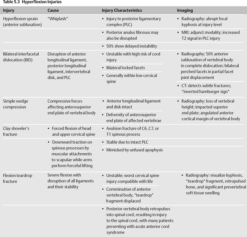
Hyperflexion Injuries (Table 5.3)
There are several types of hyperflexion injuries, in which there is compression of the anterior column and distraction of the posterior elements of the spine.
Hyperflexion Sprain (Anterior Subluxation)
Hyperflexion sprain injuries are most often caused by “whiplash” injury, usually from abrupt deceleration in a vehicle traveling less than 30 miles per hour. This mechanism often occurs when a stopped car is rear-ended. The hallmark of hyperflexion sprain is injury to the posterior ligament complex. The posterior anulus fibrosus and intervertebral disk are sometimes also disrupted, with presumptive injury to the facet capsule as well. Initially, hyperflexion sprain injuries are stable, but up to 50% of them can exhibit delayed instability.
Radiographically, hyperflexion sprain injuries often manifest by an abrupt focal kyphosis at the level of injury. Posteriorly, the interspinous and interlaminar spaces are widened. The facets become partially uncovered due to the increased kyphosis and probable loss of facet capsule integrity. There is also increased distance between the anterior cortex of the displaced vertebral body and the superior facets. In addition, the intervertebral disk space is widened posteriorly and narrowed anteriorly. MRI can be used as an adjunct modality and demonstrates increased T2 signal within the posterior ligamentary complex (PLC), signifying injury.
Bilateral Interfacetal Dislocation
In the second form of hyperflexion injury, bilateral interfacetal dislocation (BID), there is disruption of the anterior longitudinal ligament, posterior longitudinal ligament, intervertebral disk, and PLC. The inferior articular masses of the affected facet joint pass superiorly and anteriorly to the subjacent facet and are located within the neural foramina. BID is an unstable injury and is associated with a high risk of spinal cord damage. This injury is commonly referred to as “bilateral locked facets,” although this is a misnomer because the facets are not in fact locked together but are instead unstable due to the extensive ligamentous injury present. BID usually occurs within the lower cervical spine.
Radiographically, if dislocation is complete, BID exhibits at least 50% anterior subluxation of the affected vertebral body on the subjacent vertebrae (Fig. 5.2). If the facet joints are partially displaced, bilateral perched facets result, in which the superior vertebral facets are subluxed superiorly and anteriorly on the subjacent facets but are not completely dislocated. When incomplete, overall anterior subluxation is less than 50%. In both complete and partial displacement of the facets, there are often small impaction fracture fragments present that are not clinically significant. CT easily demonstrates facet dislocation as well as other, more subtle fractures that are more difficult to see on the plain radiograph. On CT, facet joint articulations resemble the cross section of a hamburger bun. With facet dislocation, the hamburger bun is inverted, corresponding to the so-called inverted hamburger sign.
Simple Wedge Compression
Wedge compression fractures are usually found within the middle to lower cervical spine, with compressive forces from hyperflexion affecting the anterosuperior end plate of the vertebral body. The anterior longitudinal ligament and intervertebral disk are intact. There is a deformity of the anterosuperior end plate of the affected vertebrae along with buckling of the anterior cortex. This fracture is stable unless the PLC is injured and fails to heal, in which case there is delayed instability.
Radiographically, there is loss of vertebral body height and impaction of the superior end plate of the vertebral body. The impacted superior end plate usually demonstrates increased density. The anterior cortical margin of the vertebral body is angulated. If there is injury to the PLC, there is widening of the interspinous and interlaminar distances (as seen in hyperflexion sprain and BID).
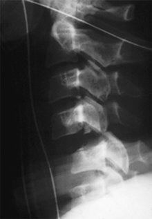
Fig. 5.2 Bilateral interfacetal dislocation. The facet joints of C4 are dislocated anteriorly with respect to C5.
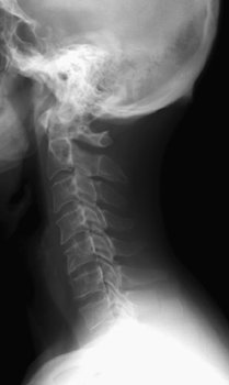
Fig. 5.3 Clay shoveler’s fracture. Note the fracture through the spinous process of C7.
Clay Shoveler’s Fracture
The clay shoveler’s fracture is an acute avulsion fracture of the C6, C7, or T1 spinous process (Fig. 5.3). This fracture is caused by forced flexion of the head and upper cervical spine, resulting in opposing action of the supraspinous and interspinous ligaments. An alternative mechanism for this injury is downward traction on the spinous processes by muscular attachments to the scapulae while the arms perform forceful lifting. The injury with a clay shoveler’s fracture is stable, as the posterior ligamentous structures are intact. The clay shoveler’s fracture is mimicked by unfused apophyses, which typically have smoother, wellcorticated margins.
Flexion Teardrop Fracture
The flexion teardrop fracture is an unstable fracture and is the most devastating cervical spine injury compatible with life. This injury is caused by severe flexion with resultant disruption of all ligaments and their associated stability. The anterior vertebral body is comminuted, with a triangular fragment, or “teardrop,” anteroinferiorly. The posterior portion of the vertebral body retropulses into the spinal canal, causing injury to the spinal cord. Patients clinically present with acute anterior cord syndrome, characterized by complete paralysis, hypesthesia and hypalgesia to the level of injury, and preservation of dorsal column function.
On the lateral radiograph, kyphosis is demonstrated along with anterior compression and vertebral body fracture. The “teardrop” fragment is displaced from the anterior and inferior aspect of the vertebral body (Fig. 5.4). Retropulsed bone from the fractured vertebral body is present within the spinal canal, and there is increased interlaminar and interspinous distance consistent with posterior ligamentous injury. Significant prevertebral soft tissue swelling usually accompanies the fracture.
Fig. 5.4 Flexion teardrop fracture. In this patient, kyphosis is centered at C5 where there is a compression deformity and fracture of the anteroinferior vertebral body end plate.
Hyperflexion Injuries with Rotation (Table 5.4)
Unilateral Interfacetal Dislocation
With unilateral interfacetal dislocation (UID), the mechanism of injury is similar to that of BID, except that the flexion force is accompanied by a rotational component. The dislocation occurs on the side opposite the direction of the rotation. The anterior longitudinal ligament, intervertebral disk, and posterior longitudinal ligaments are intact, but there is disruption of the PLC and articular joint capsule. In up to 70% of cases, there are impaction fractures involving the tip of either articular mass. These injuries are most common at C5-C6 and C6-C7. The injury is stable unless the fracture isolates the articular process. Because UID is usually a stable injury, the term unilateral locked facet is appropriate, unless the articular mass or contralateral facet is injured. CT is required when UID is present because it can detect subtle fractures and injuries that deem the injury unstable.14
In UID, the lateral radiograph demonstrates the classic “bow-tie” sign, which is due to the lack of superimposition of the articular masses at the level of injury (Fig. 5.5). The degree of anterior subluxation is greater than 3 mm but less than one half of the width of the vertebral body. Due to injury to the PLC, there is increase in the interlaminar and interspinous distances. On the AP view, rotation of the spinous processes at and above the level of involvement in the direction of the injury is observed.
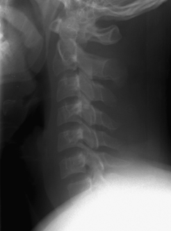
Fig. 5.5 Unilateral interfacetal dislocation. The “bow-tie” sign is present, as there is lack of superimposition of the articular masses at the level of injury.
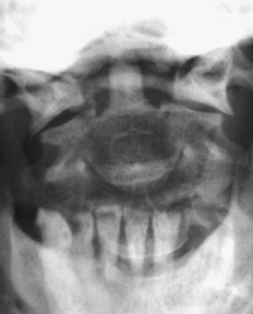
Fig. 5.6 Jefferson fracture. Note the step-off between the lateral borders of the C1 arch relative to C2.
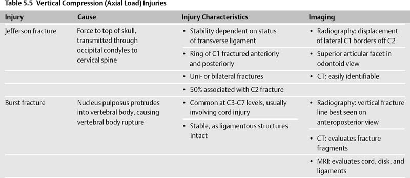
Vertical Compression Injuries (Table 5.5)
With vertebral compression (axial load) injuries, a force is delivered to the top of the skull that is transmitted through the occipital condyles to the cervical spine at the instant that the spine is straight. Two types of axial load injuries are commonly encountered.
Jefferson Fracture
In the Jefferson fracture, the ring of C1 is fractured in its anterior and posterior components. The Jefferson fracture was initially described as a four-part fracture, but two- and three-part fractures also occur. The fractures can be unilateral or bilateral. Fracture fragments are displaced laterally. Up to one half of patients have associated C2 fractures.15 The odontoid view usually shows displacement of the lateral borders of C1 off the C2 superior articular facets (Fig. 5.6). If displaced more than 7 mm, there is disruption of the transverse ligament.16 However, displacement of less than 7 mm does not exclude injury to the transverse ligament. Lateral radiographs often demonstrate fractures of the C1 arch as well as prevertebral soft tissue swelling. If the ADI is greater than 4 mm, injury to the transverse ligament is more likely. CT easily identifies a Jefferson fracture, which is an unstable injury when associated with injury to the transverse ligament, but stable when the ligament is intact. A developmental variant that mimics the Jefferson fracture is incomplete fusion of the posterior C1 arch. This is a solitary defect in the cortex of C1, whereas and Jefferson fractures involve two or more fracture foci.