KEY POINTS
1. The goal of cardiopulmonary bypass is to provide adequate gas exchange, oxygen delivery, systemic blood flow with adequate perfusion pressure while minimizing the detrimental effects of bypass.
2. Roller pumps may cause more damage to blood elements and can result in massive air embolism if the venous reservoir becomes empty.
3. Membrane oxygenators function similarly to natural lungs, imposing a membrane between the ventilating gas and the flowing blood, thereby eliminating direct contact between blood and gas.
4. During bypass, excessive and rapid warming of blood with the bypass heat exchanger must be avoided to prevent gas coming out of solution risking embolism and to avoid excessive heating of the brain with subsequent potential neurologic damage.
5. Cardiotomy suction should be minimized or cell salvage techniques used to process the cardiotomy blood as it contains microaggregates of cells, fat, foreign debris, thrombogenic and fibrinolytic elements thought to be major sources of hemolysis, and microemboli during CPB.
6. More recent data have suggested that the lower limit of autoregulation of the brain is approximately a mean pressure of 70 mm Hg in awake, normotensive subjects. On the basis of this data some clinicians are now using higher (greater than 70 mm Hg) mean pressure on bypass.
7. Critical oxygen delivery is that point at which maximum oxygen extraction is reached and oxygen consumption starts to fall.

PART I: THE CARDIOPULMONARY BYPASS CIRCUIT
I. Introduction: It is critical that anesthesiologists who provide care for patients undergoing surgery using cardiopulmonary bypass (CPB) be intimately familiar with the function of the heart–lung (H–L) machine (also referred to as the extracorporeal circuit [ECC]). In this chapter, the components of the H–L machine, the physiologic principles and pathophysiologic consequences of CPB, and the important role the anesthesiologist should play in its optimal and safe conduct are described. In Chapter 8, the medical management of patients during CPB is described.
1
The primary goal and function of CPB is to divert blood away from the heart and lungs and return it to the systemic arterial system, thereby permitting surgery on the nonfunctioning heart. In doing so, it must replace the function of both the heart and the lungs. The goal is to provide adequate gas exchange, oxygen delivery, systemic blood flow, and arterial pressure, while minimizing the adverse effect of extracorporeal circulation. This is accomplished by the two principal components of the H–L machine: The artificial lung (blood gas exchanging device or “oxygenator”) and the arterial pump. The “oxygenator” removes carbon dioxide as well as adds oxygen to provide the desired PaO2 and PaCO2, while the arterial pump supplies the energy to maintain systemic blood for arterial pressure and organ perfusion. Because the proximal ascending aorta is often cross-clamped to arrest the heart to facilitate surgery, a cardioplegia delivery system is added to minimize myocardial ischemia. Other components of the ECC include cannulae that connect to the systemic venous and arterial systems, a venous reservoir, a heat exchanger to control body temperature, field or cardiotomy suction, and various safety and monitoring devices. These components will be described in this chapter. The interested reader may find further details on CPB components in the referenced texts [1–5].
II. Components of the circuit
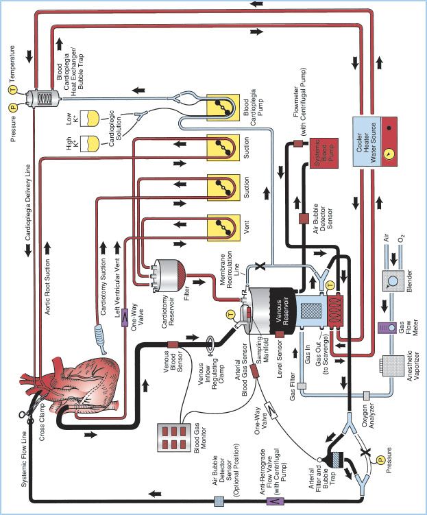
A. Overview: The essential components of the H–L machine include the CBP console, oxygenator, venous reservoir, arterial pump, cardioplegia circuit, ventilating circuit, monitoring and safety systems, and various filters. These components can be assembled in a myriad of configurations depending on perfusionist/surgeon preference and patient need. Figure 21.1 shows a detailed schematic of a typical CPB circuit. Desaturated blood exits the patient’s vena cava through a right atrium (RA)/inferior vena cava (IVC) venous cannula and is diverted to the venous reservoir by gravity siphon drainage through large-bore polyvinyl chloride (PVC) tubing. Blood is then drawn from the venous reservoir by the systemic blood pump, which can be either roller or kinetic, and pumped through a heat exchanger (integral to the membrane oxygenator [MO]). Blood then passes through the oxygenator, through an arterial filter, and back into the patient through the arterial cannula inserted into the ascending aorta. Additional parts of the circuit include a recirculation line from the arterial side of the oxygenator, which is used for priming the system and as a blood source for cardioplegia. A purge line is located on the housing of the arterial filter and is kept open during CPB to vent any air from the circuit back to the venous reservoir, or a second reservoir called cardiotomy reservoir.
Other roller pumps on the H–L machine are used for various functions including delivery of cardioplegic solution, return of shed blood via aspiration, venting of blood from intracardiac sources, or the removal of air from the venous reservoir when collapsible venous reservoir “bag” systems are used. Additional components of the CPB system include microprocessors for console control and electronic data recording, a cooler/heater which serves as an adjustable temperature water source used in conjunction with the circuit heat exchangers, an anesthetic vaporizer for the administration of volatile anesthetic agents, cardioplegia delivery system, various sensors for monitoring arterial and venous blood parameters as well as oxygen concentrations in the ventilating circuit, and various safety devices. Most of the components through which the blood passes are disposable and commercially custom-prepared to meet the specific requirements of individual cardiac teams.
Figure 21.1 Detailed schematic diagram of arrangement of a typical CPB circuit using an MO with integral hard-shell venous reservoir (lower center) and external cardiotomy reservoir. Venous cannulation is by a cavoatrial cannula and arterial cannulation is in the ascending aorta. Some circuits do not incorporate a membrane recirculation line; in these cases the cardioplegia blood source is a separate outlet connector built-in to the oxygenator near the arterial outlet. The systemic blood pump may be either a roller or centrifugal type. The cardioplegia delivery system (right) is a one-pass combination blood/crystalloid type. The cooler–heater water source may be operated to supply water to both the oxygenator heat exchanger and cardioplegia delivery system. The air bubble detector sensor may be placed on the line between the venous reservoir and systemic pump, between the pump and MO inlet or between the oxygenator outlet and arterial filter (neither shown) or on the line after the arterial filter (optional position on drawing). One-way valves prevent retrograde flow (some circuits with a centrifugal pump also incorporate a one-way valve after the pump and within the systemic flow line). Other safety devices include an oxygen analyzer placed between the anesthetic vaporizer (if used) and the oxygenator gas inlet and a reservoir-level sensor attached to the housing of the hard-shell venous reservoir (on the left). Arrows, directions of flow; X, placement of tubing clamps; P and T, pressure and temperature sensors, respectively. Hemoconcentrator (described in text) not shown. (From Hessel EA II. Circuitry and cannulation techniques. In: Gravlee GP, et al., eds. Cardiopulmonary Bypass. Philadelphia, PA: Lippincott Williams & Wilkins; 2008:64, with permission.)
B. Venous cannulation and drainage
1. Overview: Blood must be diverted into the H–L machine to keep it from passing through the heart and lungs and thereby permit access to the heart by the surgeon.
2. Central venous cannulation (Fig. 21.2)
Figure 21.2 Venous cannulation (central, intra-thoracic). Methods of venous cannulation. A: Single cannulation of RA with a “two-stage” cavoatrial cannula. This is typically inserted through the RA appendage. Note that the narrower tip of the cannula is in the IVC, where it drains this vein. The wider portion, with additional drainage holes, resides in the RA, where blood is received from the coronary sinus and SVC. The SVC must drain via the RA when a cavoatrial cannula is used. B: Separate cannulation of the SVC and IVC. Note that there are loops placed around the cavae and venous cannulae and passed through tubing to act as tourniquets or snares. The tourniquet on the SVC has been tightened to divert all SVC flow into the SVC cannula and prevent communication with the RA. (From Hessel EA II. Circuitry and cannulation techniques. In: Gravlee GP, et al., eds. Cardiopulmonary Bypass. Philadelphia, PA: Lippincott Williams & Wilkins; 2008:67, with permission.)
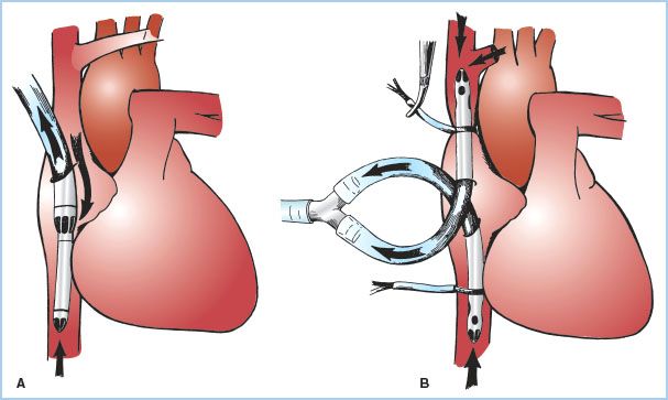
a. Single simple cannula in RA: Inserted through a purse-string suture in the RA free wall or atrial appendage. This type of cannulation tends to be unstable, does not reliably divert flow into the right ventricle (RV), and is rarely used in adult CPB.
b. Cavoatrial or “two-stage” single cannula: A single-lumen cannula with a wide proximal portion with drainage slits situated in the RA, and a narrower distal end placed into the IVC. The tip in the IVC makes this cannula more stable. It is usually inserted through a purse-string suture in the atrial appendage. Insertion may be difficult in the presence of RA masses or hardware or a prominent Eustachian valve or Chiari network. Tears produced at the junction of the IVC with the RA are difficult to manage. This is the most common type of cannulation for coronary artery and aortic valve surgery. It may not reliably prevent blood from entering the RV, and may not provide optimal myocardial cooling (especially the RA and RV). Superior vena cava (SVC) drainage and hence venous return to the H–L machine can be compromised if the junction of the SVC to the RA is kinked (which occurs when the heart is lifted up for grafting of vessels in the inferior and posterior-lateral wall).
c. Bicaval cannulation: Separate cannulae are placed into the SVC and IVC either directly or indirectly through the RA through purse-string sutures. Bicaval cannulation is most effective at totally diverting blood away from the heart. When the right heart must be opened, additional large ligatures or tapes are placed around the SVC and the IVC to prevent any caval blood from entering the atrium (and any air getting from the atrium into the venous drainage). When the caval tapes are tightened, this is termed “complete bypass.” It is critical that when these tapes are tightened that the cannulae or drainage do not become obstructed or venous hypertension (congestion) will occur. This is of particular concern in the SVC because of the potential adverse impact on cerebral perfusion; pressure in the SVC cephalad to the tip of the SVC cannula should be monitored. Bicaval cannulation is necessary whenever the surgeon plans to open the right heart (for surgery involving the tricuspid valve, RA masses, trans-atrial septal approaches to left heart, and for congenital heart surgery) and for mitral valve (MV) surgery. The latter is because retraction of the RA to view the MV causes kinking of the junction of the cavae with the RA which interferes with venous drainage, or if the surgeon approaches the MV through the RA, or for Tricuspid Valve (TV) repair. Bicaval cannulation, by diverting blood away from the right heart, minimizes cardiac warming, especially of the RA and ventricle during cold cardioplegia.
d. Impact of persistent left superior vena cava (LSVC) on venous cannulation: About 0.3% of the general population (1% to 10% of patients with congenital heart disease) will have a persistent LSVC. This is a remnant of fetal development and drains blood from the junction of the left internal jugular (IJ) and left subclavian veins into the coronary sinus, and hence into the RA. Therefore, placing cannulae in the right SVC and IVC will not be effective in diverting all of the venous drainage away from the RA. One simple solution is for the surgeon to temporarily occlude (snare) the LSVC. However, in about two-thirds of these patients, the left innominate vein is absent or small, and this maneuver may result in venous hypertension and adverse cerebral consequences. In these cases, the surgeon may place a third venous cannula in the LSVC either retrograde via the coronary sinus, or directly into the LSVC through a purse-string suture.
3. Peripheral venous cannulation: Used for minimally invasive/“port-access” approaches, surgery via left thoracotomy, or for cannulation before entering the chest (electively or emergently when bleeding is anticipated or encountered). Most commonly, venous cannulae are placed via the femoral vein (and rarely the IJ vein). If the femoral vein is used, the cannula is positioned with the tip at the SVC–RA junction. Positioning of the cannula is often guided by transesophageal echocardiography (TEE). Bicaval cannulation is possible with a special IVC cannula designed for this purpose. If a separate IJ venous cannula is placed, it is often inserted by the anesthesiologists shortly after induction and requires special attention on their part in regards to sterile technique, heparinization, and clamping and unclamping of this line for CPB. As peripheral venous cannulae are smaller and longer than directly placed cannulae, resistance to drainage is greater and may require use of augmented venous drainage (see later).
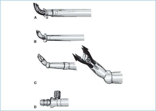
4. Venous cannulae are plastic (Fig. 21.3). Some are wire-reinforced to minimize kinking. Others designed for direct caval cannulation have curved thin metal or plastic tips for a favorable internal diameter to external diameter (ID:OD) ratio.
Figure 21.3 Venous cannulae. Drawings of commonly used venous cannulae. A: Tapered, “two-stage” RA–IVC cannula. B: Straight, wire-wound “lighthouse” tipped cannula for RA or separate cannulation of the SVC or IVC. C: Right-angled, metal-tipped cannula for cannulation of the SVC or IVC. (From Hessel EA II. Circuitry and cannulation techniques. In: Gravlee GP, et al., eds. Cardiopulmonary Bypass. Philadelphia, PA: Lippincott Williams & Wilkins; 2008:65, with permission.)

5. Types of drainage
a. Gravity: Venous drainage is usually accomplished by gravity (siphon effect). This requires that the venous drainage tubing is full of fluid (blood). Drainage is based upon the pressure difference of the column of fluid between the level of the patient and that of the H–L machine (venous reservoir). Flow is influenced by central venous pressure (intravascular volume and venous tone), height differential between the patient and the H–L machine, and resistance in the venous cannula and tubing (length, internal diameter, mechanical obstruction, or malposition of cannulae). “Chattering” of the venous lines suggest excessive drainage or inadequate venous return. Since drainage depends on a siphon, this will be interrupted if the venous line becomes filled with air.
b. Augmented venous drainage: Used when long or smaller cannulae or venous lines are employed and to permit elevation of the H–L machine to the level of the patients (all designed to decrease the prime volume or for peripheral or port-access cannulation). Two classes of systems are utilized: Vacuum-assisted and kinetic.
(1) Vacuum-assisted drainage is accomplished by attaching the venous line to a closed “hard-shell” venous reservoir (see below) to which vacuum (usually negative 20 to 50 mm Hg) is applied. Whenever augmented venous drainage is employed there is increased risk of aspirating air from around the venous cannulae, and application of a second purse-string around this site is recommended. There is also additional risk of developing positive pressure in the closed reservoir which can lead to retrograde venous air embolism. This requires inclusion of a positive pressure release valve and heightened attention on the part of the perfusionist.
(2) Kinetic-assisted drainage is accomplished by inserting a pump (usually centrifugal, but rarely a roller pump). The use of the former is easier to control and minimizes collapse of the cavae or atrium around the tip of the cannulae. This requires close attention by the perfusionist, and as with vacuum-assisted venous drainage increases the risk of air aspiration.
(3) Studies have not found use of augmented venous return to increase destruction of blood elements nor to aggravate the inflammatory response to CPB.
C. Arterial cannulation
1. Overview: The blood from the H–L machine must be returned to the systemic arterial system through an arterial cannula. These cannulae are the narrowest part of the circuit and must carry the entire systemic blood flow (“cardiac output”). The size of cannula is based on the desired blood flow (mainly influenced by patient size) and is chosen to keep blood velocity less than 100 to 200 cm/s and pressure gradients less than 100 mm Hg. Higher flows and pressures (jets) may result in trauma to blood elements and the vessel wall (“sandblasting” and dissection) and potential for reduced flow into side branches. To maximize the ID/OD ratio, the tips of the cannulae are often constructed from metal or hard plastic and the narrowest part of the arterial line is kept as short as possible. Some special tips have been designed to minimize the exit velocities and jet effects (Fig. 21.4). Most commonly the arterial cannula is inserted in the distal ascending aorta, but other sites are also used.
Figure 21.4 Arterial cannulae. Drawings of commonly used arterial cannulae. A: Tapered, bevel-tipped cannula with molded flange near tip. B: Angled, thin-walled, metal-tipped cannula with molded flange for securing cannula to aorta. C: Angled, diffusion-tipped cannula designed to direct systemic flow in four directions (right) to avoid a “jetting effect” that may occur with conventional single-lumen arterial cannulae. D: Integral cannula/tubing connector and luer port (for deairing) incorporated onto some newer arterial cannulae. (From Hessel EA II. Circuitry and cannulation techniques. In: Gravlee GP, et al., eds. Cardiopulmonary Bypass. Philadelphia, PA: Lippincott Williams & Wilkins; 2008:72, with permission.)
2. Cannulation site options (Table 21.1)
Table 21.1 Arterial cannulation sites
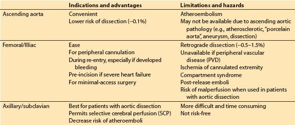
a. Ascending aorta: This is the most common approach. The cannula is inserted through one or two concentric purse-sting sutures in the distal ascending aorta and directed toward the transverse arch (NOT toward one of the arch vessels). Dislodgement of atheromatous material from the cannulation site is a primary concern. Palpation of the aorta may not be sensitive enough to detect atheroma, and many advocate imaging of the intended site for cannulation with epiaortic ultrasound. When placed in the ascending aorta, some groups use long cannulae directed into the proximal descending aorta to minimize jet effects in the arch, while others use very short cannulae inserted only 1 to 2 cm into the aorta. Dissection associated with ascending aortic cannulation occurs in less than 0.1% of patients. The ascending aorta may not be a suitable cannulation site for various reasons including presence of severe atherosclerotic disease, aortic dissection, and for minimal access surgery, left thoracotomy surgery, and risk of or rescue from hemorrhage during repeat sternotomy.
b. Femoral or external iliac artery: This is the second most common approach and is used when ascending aortic cannulation is not desirable or feasible. However, this approach has a number of limitations including risk of dissection (0.5% to 1%), risk of atheroembolism (especially into brain and heart), malperfusion of the brain and other organs in the presence of extensive aortic dissection, and ischemia of the cannulated limb. The use of TEE surveillance of the descending aorta is recommended when CPB is initiated and periodically throughout CPB in order to detect the presence of a retrograde dissection. Prolonged femoral cannulation times may result in the release of emboli and acidotic products from the limb with reperfusion and for subsequent development of compartment syndrome in the limb. To minimize leg ischemia, some groups sew a graft onto the side of the femoral artery and insert the arterial cannula into this graft so that blood flows both retrograde and antegrade, while others insert a supplemental arterial cannula into the distal femoral artery.
c. Axillary/subclavian artery cannulation is often advocated in the presence of aortic dissection or severe atherosclerosis. These vessels are usually free of significant atherosclerosis, and malperfusion and iatrogenic dissection are probably less common than with femoral cannulation. The artery is approached through an infraclavicular incision, and the cannula can be placed either directly into the vessel, or via a graft sewn onto the side of the artery. The right artery is favored since it permits selective cerebral perfusion (SCP) if circulatory arrest is required (see later). If the vessel is cannulated directly (i.e., not through a side arm graft), then the artery in the contralateral upper extremity (radial or brachial) must be used for systemic arterial pressure monitoring during CPB.
d. Innominate artery: Rarely used approach. There is concern about adequacy of flow around the cannula (which is directed retrograde toward the ascending aorta) into the distal vessel and hence the brain.
D. Venous reservoir
1. Overview: The venous reservoir is designed to receive the venous drainage from the patient. The reservoir is placed immediately before the systemic arterial pump to serve as a “holding tank” and act as a buffer for fluctuation and imbalances between venous return and arterial flow. It also serves as a high-capacitance (i.e., low-pressure) receiving chamber for venous return and hence facilitates gravity drainage of venous blood. Additional venous blood may become available from the patient when CPB is initiated and systemic venous pressure is reduced to low levels. Thus, as much as 1 to 3 L of blood may need to be translocated from the patient to the ECC when full CPB begins. This reservoir may also serve as a gross bubble trap for air that enters the venous line, as the site where blood, fluids, or drugs may be added, and as a ready source of blood for transfusion into the patient. One of its most important functions, however, is to provide a source of blood if venous drainage is sharply reduced or stopped; this provides the perfusionist with reaction time in order to avoid “pumping the CPB system dry” and risking massive air embolism. These reservoirs usually include various filtering devices. There are two classes of reservoirs:
a. Rigid hard-shell plastic, “open” venous canisters: Advantages include ability to handle venous air more effectively, simple to prime, larger capacity, and ability to apply suction for vacuum-assisted venous return. Most hard-shell venous reservoirs incorporate macro- and microfilters often coated with defoaming agents and can also serve as the cardiotomy reservoir (see later) by directly receiving suctioned and vented blood. Their ability to remove gaseous microemboli (GME) varies.
b. Soft-shell, collapsible plastic bag, “closed” venous reservoirs: These reservoirs eliminate the gas–blood interface and reduce the risk of massive air embolism because they will collapse when emptied and do not permit air to enter the systemic pump. Closed collapsible reservoirs also make the aspiration of air by the venous cannulae more obvious to the perfusionist, but require a way of emptying the air out of the reservoir. When soft-shell reservoirs are used, a separate cardiotomy reservoir is required (see later). Because of reduction of the gas–blood interface, their use may be associated with less inflammatory activation. Data on comparative clinical outcome with use of the two types of venous reservoirs are conflicting and inconclusive [6].
E. Systemic (arterial) pump: There are currently two types of blood pumps used in the CPB circuit: Roller and kinetic (most commonly called centrifugal) (Table 21.2). In the United States, kinetic pumps are used in approximately 50% of all procedures.
Table 21.2 Comparison of roller versus centrifugal pumps

1. Roller pump (Fig. 21.5)
Figure 21.5 Roller pump. Drawing of a dual roller pump and tubing. The principle of the roller pump is demonstrated by the hand roller in the lower drawing moving along a section of tubing pushing fluid ahead of it and suctioning fluid behind it. The upper four drawings in sequence (A–D) show how roller pump B first moves fluid ahead of it and suctions fluid behind it (A). As the pump rotates clockwise, the second roller A begins to engage the tubing (B). As the rotation continues there is a very brief period with volume trapped between the two rollers (C) and no forward flow, which imparts some pulsatility. In position D, roller B leaves the tubing, while the second roller A continues to move fluid in the same direction. Not shown are the roller pump backing plate, tubing holders, and tube guides for maintaining the tubing within the raceway. Fluid flows in direction of the arrows. (From Stofer RC. A Technic for Extracorporeal Circulation. Springfield, IL: Charles C. Thomas; 1968:22, with permission.)
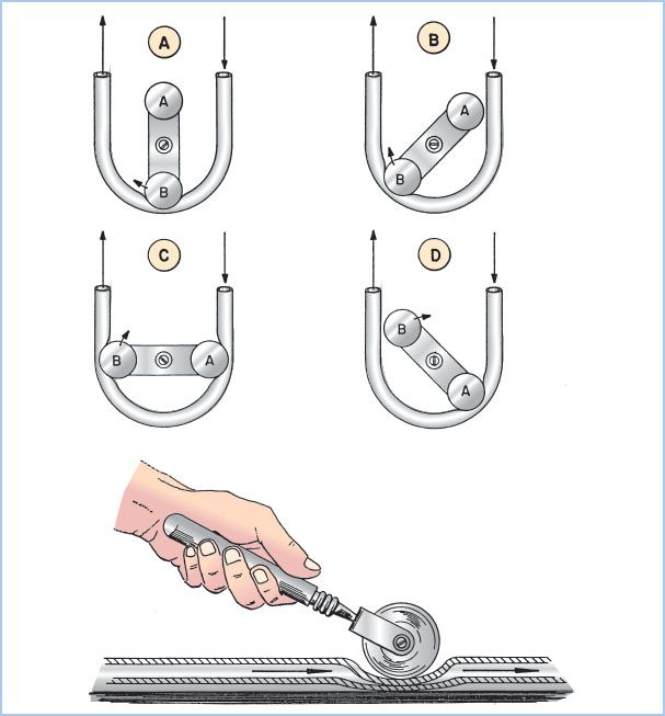
a. Principles of operation: Blood is moved through this pump by sequential compression of tubing by a roller against a horseshoe-shaped backing plate or raceway. A typical pump has two roller heads configured 180° apart to maintain continuous roller head contact with the tubing. The output is determined by the stroke volume of each revolution (the volume within the tubing which is dependent upon the tubing size [internal diameter] and the length of the compressed pathway times the revolutions per minute [rpm]). Flow from a systemic roller pump increases or decreases linearly with rpm. With larger ID tubing (e.g., 1/2-inch ID), lower rpm are required to achieve the same output compared to smaller ID tubing. The total pump output is displayed in milliliters or liters per minute on the pump control panel. Roller pumps are also used to deliver cardioplegia solution, remove blood and air from heart chambers or great vessels, and suction shed blood from the operative field (see later).
b. Adjustment of occlusion: To minimize hemolysis, the occlusion must be properly set. Occlusion describes the degree to which the tubing is compressed between the rollers and the backing plate. An under-occlusive pump will allow retrograde movement of fluid when the pressure in the downstream location exceeds that generated by the pump, reducing forward flow. Conversely, an over-occlusive pump will create cellular damage (red blood cell [RBC] hemolysis, white blood cell [WBC] and platelet activation) and excessive wear on the tubing with release of microparticles (“spallation”). Occlusion is set by the perfusionist by adjusting the distance between the raceway and each of the roller heads. Typically, occlusion is adjusted to be barely nonocclusive.
2
c. Advantages and disadvantages: Roller pumps have the advantages of being simple, effective, low-cost, having a low priming volume, and producing a reliable output which is afterload independent. A primary disadvantage is that since output is afterload independent, if the arterial line becomes occluded, high pressure will develop which may cause rupture of connections in the arterial line. If inflow is obstructed, roller pumps can generate high negative pressures creating microbubbles (“cavitation”) and RBC damage. Roller pumps may cause more damage to blood components and can result in massive air embolism if the venous reservoir becomes empty. They do not adjust to changes in venous return and require more careful attention by the perfusionist.
2. Centrifugal pumps (Fig. 21.6)
Figure 21.6 Centrifugal pumps. Drawings of centrifugal pump-heads. A cross-sectional view of a smooth, cone-type pump is shown on the top. Blood enters at A and is expelled on the right (B) due to kinetic forces created by the three rapidly spinning cones. Impeller-type pumps with vanes are shown in the bottom drawings. (Modified from Trocchio CR, Sketel JO. Mechanical pumps for extracorporeal circulation. In: Mora CT, ed. Cardiopulmonary Bypass: Principles and Techniques of Extracorporeal Circulation. New York, NY: Springer-Verlag; 1995:222, 223, with permission.)
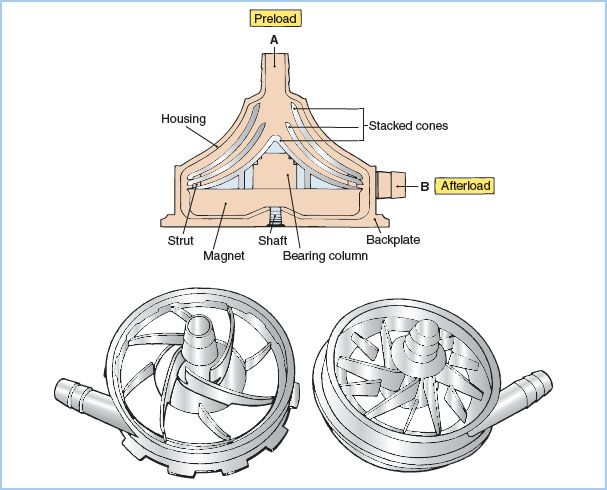
a. Principles of operation: Centrifugal pumps consist of a nest of smooth plastic cones or a vaned impeller located inside a plastic housing. When rotated rapidly (2,000 to 3,000 rpm), these pumps generate a pressure differential that causes the movement of fluid. Smaller, vaned, impeller-type rotary (centrifugal) pumps are being used clinically in place of the traditional cone-type centrifugal pump These have smaller prime volumes and may cause less hemolysis.
b. Advantages and disadvantages: Unlike roller pumps, these devices are totally nonocclusive and afterload dependent (an increase in downstream resistance or pressure decreases forward flow). This has both favorable and unfavorable consequences. Flow is not determined by rotational rate alone, and therefore a flowmeter must be incorporated in the outflow line to quantify pump flow. Furthermore, when the pump is connected to the patient’s arterial system but is not rotating, blood will flow backward through the pump and out of the patient unless the CPB systemic line is clamped or a one-way valve is incorporated into the arterial line. This can cause exsanguination of the patient or aspiration of air into the arterial line (from around the purse-string sutures). On the other hand, if the arterial line becomes occluded, these pumps will not generate excessive pressure and will not rupture the systemic flow line. Likewise, they will not generate as much negative pressure and hence as much cavitation and microembolus production as a roller pump if inflow becomes occluded.
A reputed advantage of centrifugal pumps over roller pumps is less risk of pumping massive air emboli into the arterial line; centrifugal pumps will become deprimed and stop pumping if more than approximately 50 mL of air is introduced into the circuit. However, they will pass smaller but still potentially lethal quantities of smaller bubbles. A number of studies have demonstrated that centrifugal pumps cause less trauma to blood elements, less activation of coagulation, produce fewer microemboli, and may be associated with better clinical outcomes than roller pumps [6].
3. Pulsatile flow and pulsatile pumps
a. Overview: Most roller pumps produce only a low-amplitude, high-frequency pulsatile flow of little physiologic relevance, while centrifugal pumps produce a nonpulsatile flow. The importance of pulsatile flow has long been debated. (See later in this chapter and paper by Murphy et al. [6].)
b. Many groups use roller pumps and centrifugal pumps that can be programmed to produce pulsatile flow.
c. A major problem with efforts to produce physiologically effective pulsatile flow in the patient is the dampening effect of various components distal to the arterial pump including the MO, arterial filter, and the arterial cannula. It has been calculated that very little of the pulsatile energy generated is actually delivered into the patient’s arterial system.
F. The oxygenator (artificial lung or gas exchanging device)
1. Although numerous types of oxygenators have been used in the past, currently only MOs are used in most parts of the world. These produce less blood trauma and microemboli, permit more precise control of arterial blood gases, and improve patient outcomes as compared with bubble oxygenators. Virtually all current MOs are positioned after the arterial pump because the resistance in the blood path requires blood to be pumped through them, and to minimize the risk of pulling air through the membrane and producing GME. Most oxygenators also include an integral heat exchanger (see later).
3
MOs function similarly to natural lungs, imposing a membrane between the ventilating gas and the flowing blood and eliminating direct contact between the blood and the gas. At least three types of membranes are used:
a. True membranes: These usually consist of thin sheets of silicone rubber wrapped circumferentially over a spool.
b. Microporous polypropylene (PPL) membranes: Usually configured in longitudinal bundles of narrow hollow fibers, but occasionally as folded sheets of membrane. The pores fill with autologous plasma which serves as the “membrane” through which gas exchange occurs. With excessive pressure in the blood path or over prolonged time, plasma may leak through the membrane (which degrades gas transfer), while excessive negative pressure can lead to entrainment of air emboli. In hollow fiber MOs, the blood typically flows outside the hollow fibers, while ventilating gases flow through the hollow fibers (in a counter-current direction).
c. Poly-methyl pentene (PMP) diffusion membranes: Hollow fiber MOs made of a new non porous plastic, PMP, are true membranes. This has the advantage of minimizing the risk of plasma leak and microair aspiration and permits prolonged oxygenation(days). Gas exchange occurs by diffusion across this true membrane. An important limitation is that it does not appear to allow transfer of volatile anesthetics and therefore intravenous anesthetics must be employed during CPB. Because of this limitation and because they are more expensive, PMP “diffusion” MOs are not commonly used for conventional CPB, at least in the United States, but because of their reduced risk of plasma leak (“oxygenator pulmonary edema”) are commonly used for long term extracorporeal support (e.g., extracorporeal membrane oxygenation [ECMO]).
2. MOs were thought to serve as bubble filters and to prevent venous GME from passing into the arterial system, but it is now recognized that the majority of venous gas emboli transit through MOs. The effectiveness of GME removal varies among MOs [6]. This limitation is why teams must make every effort to minimize the entrainment and administration of air into the venous drainage system.
3. Control of gas exchange and gas supply to the MO: Gas exchange by MO is controlled similarly to normal lungs. Arterial carbon dioxide levels are controlled by flow of fresh gas (commonly called “sweep gas flow”) through the oxygenator (comparable to alveolar ventilation), and arterial PO2 is controlled by varying fractional inspired oxygen (FIO2). Oxygenators require a gas supply system. This typically includes a source of oxygen and air (and occasionally carbon dioxide), which passes through a blender. An oxygen analyzer should be incorporated in the gas supply line after the blender. An anesthetic vaporizer is also placed in the gas supply line near the oxygenator. Volatile anesthetic liquids may be destructive to the plastic components of ECCs; therefore, care must be taken when filling them with volatile agents. A method of scavenging waste gas from the oxygenator outlet should be provided.
G. Heat exchanger
1. Overview: The passage of blood through the ECC results in heat loss and patient cooling. To maintain normothermia, heat must be added to the circuit. This is accomplished with a heat exchanger, which may also be used to intentionally cool and rewarm the patient. Heat exchangers consist of heat-exchanging tubes (often metal) through which the blood flows. These tubes are surrounded by water of varying temperatures. As mentioned earlier, heat exchangers are often incorporated in the oxygenator.
2. Heater–cooler. To control the temperature of the water flowing through the heat exchanger, a heater–cooler device adjusts the water temperature and pumps it through the heat exchanger (counter-current with the blood flow).
4
3. Excessive gradients between the blood and water temperature should be avoided. Most groups avoid gradients greater than 10°C. Proper conduct of heating and cooling requires monitoring of the temperature of the water going to the heat exchanger, and of the venous and arterial blood entering and leaving the H–L machine. Excessive warming can lead to gases coming out of solution and causing GME and could cause excessive heating of the brain. Currently, most groups limit the inflow temperature of the arterial blood to 37°C and limit the inflow temperature of the water entering the heat exhanger to 40°C. However, acceptable or optimal temperature gradients have not been conclusively determined.
4. Separate heat exchangers are also used in the cardioplegia circuits (see below).
H. Cardioplegia delivery system or circuit
1. Overview: When the aorta is cross-clamped (distal to the aortic valve but proximal to the arterial inflow cannula) to provide a quiet operative field or access to the aortic valve, the heart is deprived of coronary perfusion and becomes ischemic. This is usually managed by perfusing the heart with cardioplegia solutions. (See also Chapter 23 for further discussion on myocardial protection.)
2. Route of delivery of cardioplegia solutions
a. Aortic root: A cannula is inserted in the aortic root (proximal to the cross-clamp). Typically this has a “Y” connector: One limb is connected to the cardioplegia delivery system and the other to suction (to vent the left ventricle [LV] or aspirate air). The cardioplegia solution is delivered into the aortic root and thence into the coronary arteries. This is not effective in the presence of severe aortic regurgitation or when the aortic root is open; it is also less effective in the presence of severe proximal coronary artery stenosis. Ideally, pressure in the aortic root should be measured during administration of the cardioplegia to assure adequate coronary flow.
b. Directly into the coronary ostia: Special hand-held cannulae are placed directly into the right and left main coronary arteries for delivery of the cardioplegia solutions. This is commonly done in the presence of aortic regurgitation or when the aortic root is open.
c. Retrograde into the coronary sinus: Balloon-tipped cannulae are inserted blindly (or under direct vision if the RA is opened) into the coronary sinus through a purse- string suture in the low lateral wall of the RA. TEE may be helpful in guiding and assessing placement. Many of these cannulae have a pressure port near the tip so that the pressure in the coronary sinus can be monitored during perfusion (ideally maintained between 30 and 50 mm Hg). Retrograde administration of cardioplegia may be advantageous in the presence of severe coronary artery stenosis or aortic regurgitation and during aortic valve surgery. However, it may provide inferior protection of the RV.
3. Delivery systems. These vary in their complexity. If blood cardioplegia is being used, blood is taken out of the arterial perfusion line following oxygenation and mixed with the crystalloid cardioplegia solution (usually at a blood:crystalloid ratio of 4 to 6:1). This may be accomplished by using two separate roller pumps, or with a single roller pump which drives two sets of tubing of different sizes (to produce the proper flow ratio). The mixture is then passed through a dedicated heat exchanger. Microfiltration may be added and pressures and temperatures are monitored. More complex delivery systems are in use which permit rapid change of the concentration of various components in the cardioplegia solution.
I. Cardiotomy, field suction, cell salvage processors, and savers
1. Overview: During CPB there is often considerable bleeding into the surgical field due to systemic heparinization and persistent pulmonary and coronary venous drainage. It is usually not feasible to discard this large volume of blood via conventional discard suction. Traditionally, this blood is removed from the field by roller pumps on the H–L machine (“cardiotomy suckers”) and returned to the H–L machine via the cardiotomy reservoir (which includes filters and, as noted above, is commonly incorporated into the hard-shell venous reservoir, but must be added separately when a soft-shell reservoir is used). The cardiotomy suction should not be used until the patient is adequately anticoagulated and should be discontinued as soon as reversal with protamine is commenced (to avoid clotting of blood in the H–L machine).
5
2. Hazards of cardiotomy blood: Cardiotomy blood contains microaggregates of cells, fat, foreign debris, and thrombogenic and fibrinolytic factors, and is thought to be a major source of microemboli and hemolysis during CPB. For these reasons cardiotomy suction should be used sparingly.
3. An alternative strategy is to suction the field blood into a cell salvage washer/processor/saver system (or to process the blood that has been suctioned into a stand-alone cardiotomy reservoir with this cell salvage system before returning it to the H–L machine). These devices wash the blood with saline, and separate the red cells from the plasma and saline by centrifugation with the intent of reducing the microemboli, fat, etc. It also removes plasma proteins, platelets, heparin, and some of the WBCs, retaining concentrated RBCs (hematocrit about 70%). Not all processors are equally effective at removing fat, and the salvaged blood may have to be specially filtered before administration. Some of the problems associated with the use of cell processors include delayed availability and turnover time (not adequate in the face of rapid hemorrhage) and loss of platelets and coagulation factors (resulting in a consumptive coagulopathy if >6 bowls or 1,500 mL of blood is processed). Comparative studies of cardiotomy suction versus cell processors have produced conflicting results [6].
J. Venting
1. Overview: It is important that both the RV and LV are decompressed during CPB to improve surgical exposure, reduce oxygen demands of the myocardium, and attenuate damage to the heart from overdistention.
2. The RV is readily visible to the surgeon, and decompression depends on adequacy of venous drainage. The LV is more difficult to observe, has more adverse consequences if distended, and requires various strategies for venting.
3. Consequences of distention of the left heart:
a. Stretches myocardium causing ventricular dysfunction
b. Myocardial ischemia: Impairs subendocardial perfusion and increases myocardial oxygen needs
c. Increases left atrial pressure, leading to pulmonary edema and hemorrhage
d. Interferes with surgical exposure
4. Distention of the left heart is likely to occur when the LV is unable to empty (e.g., on initiation of CPB, in the presence of aortic regurgitation, during cardiac arrest, aortic cross-clamping, and administration of antegrade cardioplegia, during ventricular fibrillation, and following aortic cross-clamp release).
5. Sources of blood coming into the left heart during CPB:
a. Bronchial venous drainage (normal ~100 mL/min)
b. Systemic venous blood that bypasses venous cannulae and passes through right heart and lungs
c. Aortic regurgitation
d. Patent ductus arteriosus (PDA) (~1/3,500 adults)
e. Atrial septal defect (ASD), Ventricular septal defect (VSD)
6. Assessment of adequacy of decompression of the left heart by inspection or palpation is difficult because of its position and thick walls of the LV. The best method of evaluating the adequacy of LV decompression is TEE.
7. Methods of venting or decompressing the left heart (see Fig. 21.7 and Table 21.3): Cannulae are inserted in various locations and attached to tubing connected to roller pumps which transfers the blood to the venous or cardiotomy reservoirs. The tubing should first be placed under a level of fluid to assure that it is sucking and not emitting air, and the rate of suction must be constantly adjusted to avoid excessive (risk of damage to heart or aspirating air) or inadequate (overdistention) venting.
Table 21.3 Methods of venting the left heart
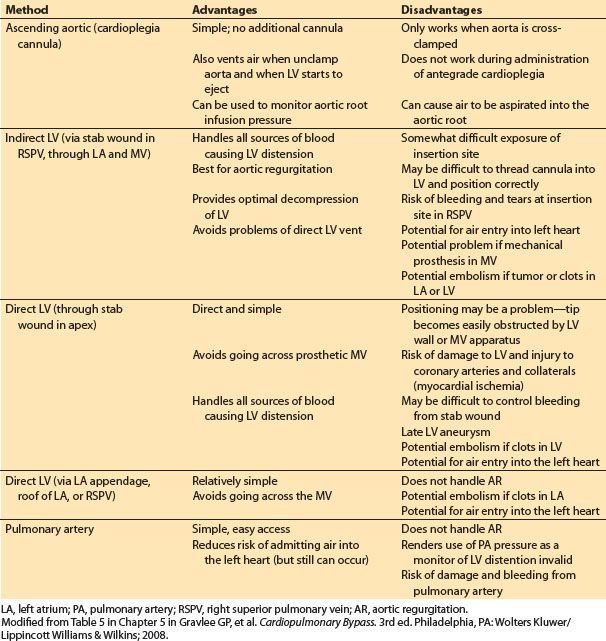
Figure 21.7 Sites for venting the left heart. A: Aortic root cannula; one limb of the “Y” is connected to the cardioplegia delivery system and the other limb to suction (siphon or roller pump) for venting the aortic root and hence the LV. B: Cannula inserted at the junction of the right superior pulmonary vein with the left atrium and then threaded through the left atrium and MV and into the LV. C: Cannula inserted directly into the apex of the LV. D: Cannula is inserted into the pulmonary artery. AO, aorta; PA pulmonary artery; LA, left atrium. (From Hessel EA II. Circuitry and cannulation techniques. In: Gravlee GP, et al., eds. Cardiopulmonary Bypass. Philadelphia, PA: Lippincott Williams & Wilkins; 2008:90, with permission.)
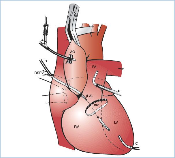
a. Aortic root vent (one limb of the antegrade cardioplegia cannula): This is the most common technique used during coronary artery bypass graft (CABG) surgery. Suction is applied to the antegrade cardioplegia cannula (directly or via a side branch). Aortic root venting of the LV is only effective when the aorta is cross-clamped, when antegrade cardioplegia is not being administered, and when the aortic root is not opened.
b. LV vent placed via the right superior pulmonary vein: A cannula is inserted at the junction of the right superior pulmonary vein with the left atrium and then threaded through the left atrium and MV into the LV. This method is used during aortic and MV surgery (especially in the presence of aortic regurgitation) and for patients with poor LV function.
c. LV vent placed directly through the LV apex: This is rarely used today because of difficulty in positioning and bleeding after removal.
d. Vent placed through the left atrial appendage or the top of the left atrium (into either the left atrium or LV). Rarely used.
e. Vent placed in the main pulmonary artery: This method minimizes the risk of air entry into the left heart (although it can still occur). It does not provide reliable decompression of the LV in the presence of aortic regurgitation, and closure of the incision in the pulmonary artery can be problematic in patients with pulmonary hypertension.
8. Complications of venting the left heart include systemic air embolism, bleeding, damage to cardiac structures, dislodgement of thrombi, calcium, tumor, etc., and MV incompetence. A critical complication is inadvertent pumping of air into the heart via these vent lines. This occurs if tubing is misaligned in the roller pump-head or if the pump is in reverse mode. Air can also enter the left heart when these lines are inserted or removed; therefore, the volume and pressure in the left heart should be high at these times and ventilation interrupted.
9. Any time the heart is opened, even by simply placing a catheter in a chamber, air may collect in the heart. If not removed, this air will embolize with resumption of cardiac contractions. Even right-heart air has the potential to pass into the left heart via septal defects or through the lungs. In addition to vigorous attempts at removal of all air before closing the left heart, the use of venting at the highest point of the aorta is considered the final safety maneuver against systemic air embolism. This is most commonly accomplished using the antegrade cardioplegia cannula (see above) which is placed on suction. TEE is particularly useful in assessing the adequacy of deairing. Some surgical teams often flood the surgical field with carbon dioxide during open cardiac procedures. Because of carbon dioxide’s increased solubility there is a potential for reduction of microemboli.
K. Ultrafiltration/hemoconcentrators. A hemofiltration device (also referred to as ultrafiltration) consists of a semipermeable membrane which separates blood flowing on one side (under pressure) and air (sometimes under vacuum) on the other side. Water and small molecules (sodium, potassium, water-soluble non–protein-bound anesthetic agents) can pass through it and be removed from the blood, but not protein or cellular components of the blood. Hemoconcentrators are used to eliminate excess crystalloid and potassium, and to raise hematocrit (hemoconcentrate). They may also remove inflammatory mediators and hence reduce the systemic inflammatory response syndrome (SIRS). The device is usually placed distal or after the arterial pump with drainage into the venous limb or reservoir. It can be placed in the venous limb of the circuit but would require a separate pump. Five hundred to 2,000 mL or more of fluid may be removed during an adult case. When using post-bypass (but before reversing heparin) it is referred to as “modified ultrafiltration” or “MUF.” MUF is commonly used in pediatric cases but rarely in adult cases [4,7].
L. Filters and bubble traps
1. Overview: CPB generates macro- and microemboli of gas, lipids, and other microparticles (WBCs, platelets, foreign debris) which must be filtered out.
2. Types and location: Many different types of filters (screen and packed fibers [“in-depth”], made of various materials) with various pore sizes are employed in multiple locations in the ECC. These sites include the venous and cardiotomy reservoirs, as part of the oxygenator, in the arterial and cardioplegia lines, and blood administration sets (including the cell processor), and the gas going to the oxygenator. The “in-depth filters” mainly work by adsorption. The clinical importance of the various types of filters remains controversial [6].
3. Arterial line filter/bubble trap: Most groups employ a microfilter/bubble trap on the arterial line, especially to reduce air embolization [6]. If used, often a clamped bypass line is placed around the filter in case the filter becomes obstructed and a vent line with a one-way valve runs from the filter/bubble trap to the venous reservoir to vent any trapped air.
4. The employment of leukocyte-depleting filters in various locations in the circuit is advocated by some, but their benefit remains to be proven.
M. Safety devices and monitors on the H–L machine
1. Monitors (see Table 21.4)
Table 21.4 Monitors and safety devices
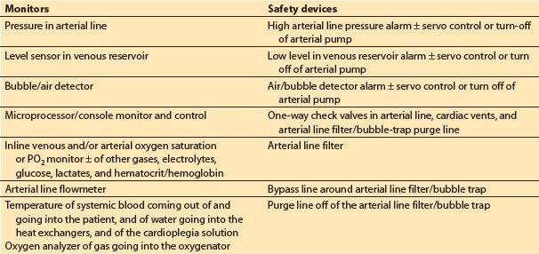
a. Microprocessor/console monitor and control. Many of the current commercial H–L machines include a microprocessor-driven monitor that displays and controls various functions of the machine and hemodynamic data from the patient.
b. Inline venous and arterial oxygen saturation, ± other blood gases, electrolytes, glucose, and hematocrit.
c. Pressure in arterial line: This should be measured proximal to the arterial line filter/bubble trap and distal to the oxygenator. Prior to initiation of CPB, the pressure should reflect a pulsatile wave that correlates with patient’s arterial pressure (to confirm proper intra-arterial placement of the arterial cannula). Excessively high arterial infusion line pressure during CPB (relative to patient’s arterial pressure) indicates a problem in the arterial flow delivery system or at the cannula tip, bearing in mind that there should always be a considerable (50 to 150 mm Hg) pressure gradient across the aortic cannula. Pressures in the line post-CPB can give clues to true systemic pressures. Some also advocate monitoring the pressure proximal to the MO; high gradients (>100 mm Hg) suggest oxygenator dysfunction.
d. Level sensor in venous reservoir
e. Bubble/air detector
f. Arterial line flowmeter: This is required when using a centrifugal systemic arterial pump, and desirable even when using a roller pump.
g. Temperature: Water-to-heat exchanger and of blood being delivered to the patient
h. Oxygen analyzer of gas delivered to oxygenator
2. Safety devices (see Table 21.4)
a. Low-level alarm ± servo control/turn-off of arterial pump
b. High arterial line pressure alarm ± servo control/turn-off of arterial pump
c. Air/bubble detector and alarm ± servo control/turn-off of arterial pump
d. One-way check valves in the arterial lines, cardiac vents, and arterial filter/bubble-trap purge lines
e. Arterial line filter
f. Bypass line around arterial line filter/bubble trap
g. Purge line off of arterial line filter/bubble trap
3. Emergency personnel, supplies, and equipment
a. Second perfusionist
b. Battery backup for H–L machine including the pumps and monitors
c. Portable lighting and flashlights
d. Backup-oxygen supply (cylinders with regulators)
e. Hand cranks to drive arterial and other pumps
f. Spare oxygenator
III. Special topics
A. Surface coating. Many commercial circuits coat all of the surfaces which come in contact with blood (tubing, reservoirs, oxygenators) with various substances (proprietary) designed to minimize the activation of blood components. Many of these coatings include heparin (which should be avoided in patients with heparin-induced thrombocytopenia [HIT]). The clinical benefits of any or of one type of coating over another remains controversial [6].
B. Miniaturized or minimized circuits: By reducing the surface area and prime volume, miniaturized circuits reduce the amount of hemodilution (resulting in less transfusions) and are purported to reduce the inflammatory response to CPB (producing improved clinical outcomes) [8]. They often feature a closed (veno-arterial loop) circuit (i.e., no venous reservoir or cardiotomy suction) and kinetic-assisted venous drainage. A sophisticated air detection and elimination system is required, as well as stringent avoidance of air entrance in the venous line. Concerns about safety (especially air embolization), inability to handle fluctuations in venous return (especially if the patient has a large blood volume or experiences exsanguination), and lack of cardiotomy and field suction require careful consideration. These systems require close communication amongst all team members. Miniaturized circuits are rarely used in the United States, but may be used more commonly in Europe. Their use is usually limited to uncomplicated CABG and aortic valve surgery, cases associated with minimal intravascular volume shifts and limited need to scavenge much blood from the surgical field.
C. Pediatric circuits. The major challenges with pediatric CPB are related to the small blood volume of the patient compared with the prime volume of the ECC, and the small venous and arterial cannulae required by the small-sized vessels. Pediatric cardiac surgery groups and industry have made great strides in miniaturization and reduction of priming volumes (some a little at 100 to 200 mL) by including augmented venous return and elevating and the H–L machine closer to the patient (allowing the use of shorter and narrower tubing). Most pediatric surgery centers in North America include albumen in the prime; packed red blood cell or whole blood and fresh frozen plasma are often used for infants [7]. Some groups exclude arterial microfilters and others use an oxygenator which has an integrated “arterial” microfilter. In distinction to adult CPB, inline arterial blood gas monitoring is employed by the vast majority of North American pediatric centers. (See additional discussion in Chapter 14.)
D. Cerebral perfusion during circulatory arrest
1. Overview: Circulatory arrest is often required for conduct of surgery involving the aortic arch, and in congenital heart surgery. Deep hypothermia (<18°C) is used to minimize cerebral injury. For periods of circulatory arrest exceeding 25 to 30 min, two strategies for cerebral perfusion are utilized. The benefits and preference of one over the other remain controversial. (See additional discussion in Chapters 24 and 25.)
2. Retrograde cerebral perfusion (RCP): The arterial line from the H–L machine is connected to the SVC cannula (in the case of bicaval cannulation), or to a cannula inserted through a purse-string in the SVC. The SVC is occluded between the entrance of the catheter and the junction with the RA. Cold blood (15 to 18°C) is then pumped at flow rates of 250 to 500 mL/min and pressures maintained between 20 and 40 mm Hg. It may be desirable to measure the pressure via a catheter placed directly into the right internal jugular (IJ) vein, since valves may reduce the amount of flow and pressure being delivered into this vein. If pressure is measured in this location, it is probably prudent to keep the pressure <25 mm Hg to minimize cerebral edema. An additional benefit of RCP is that atheroemboli and air in the carotid vessels may be “washed out.”
3. Antegrade cerebral perfusion or selective cerebral perfusion (SCP): Catheter(s) (sometimes with balloon cuffs) connected to the arterial line are inserted into the right innominate or carotid artery or the left carotid and subclavian artery. Cold blood is then infused at a rate of about 10 mL/kg/min and a pressure of about 30 to 70 mm Hg. This technique provides more cerebral blood flow than RCP but adds a risk of arterial trauma and embolization. If the systemic arterial cannula had been inserted into the right subclavian artery (see above), then selective perfusion of the right carotid artery can be accomplished by occluding the proximal innominate artery. If the arterial cannula in the subclavian has been placed via a graft sewn onto the side of the artery, the pressure in the right radial or brachial line provides monitoring of the cerebral perfusion pressure. Obviously this provides only unilateral perfusion and relies on an adequate Circle of Willis to perfuse the left side of the brain.
E. Less common cannulation
1. Minimally invasive or port access CPB involves use of smaller incision and often smaller or specially designed venous and arterial cannulae for transthoracic placement, or peripheral cannulation. This may require use of augmented venous drainage and increase the risk of aortic dissection associated with femoral artery inflow. Peripherally placed retrograde coronary sinus catheters (via the right IJ vein by the anesthesiologist), and aortic balloon occlusion catheters and antegrade cardioplegia cannulae (passed via the femoral artery) are used. These require TEE and fluoroscopic guidance for proper placement.
2. Right thoracotomy. This approach gives excellent views of the MV and RA, but aortic cannulation, occlusion of the ascending aorta, administration of antegrade cardioplegia, and deairing of the LV are problematic. Often some of the minimally invasive cannulation techniques mentioned above are employed.
3. Left thoracotomy. This approach is used for surgery on the descending thoracic aorta and occasionally for redo MV surgery and CABG surgery for revascularization of the lateral or posterior heart. Venous cannulation is problematic. Peripheral cannulation of the RA via the femoral vein is a commonly employed option (see above). For descending thoracic aortic surgery, isolated partial left heart bypass (LHB) can be accomplished cannulating the left atrium or ventricle directly or via a purse-string in the left superior pulmonary vein or left atrial appendage for venous outflow and the distal aorta or femoral artery for arterial return. The ECC for partial LHB does not require an oxygenator or reservoir and may not include a heat exchanger, typically employs a centrifugal pump and is heparin coated and permits minimal systemic heparinization, but it only supplies oxygenated blood to the lower half of the body. Flows are typically about 1 to 1.5 L/min/M2 and adjusted to adequately decompress the left heart and maintain adequate pressures in the lower and upper part of the body. Perfusion of the upper half of the body (especially to the heart and brain) is provided by the LV and oxygenation to both parts must be provided by the patient’s own lung. Management of partial LHB is quite challenging and requires excellent communication between the anesthesiologist and perfusionist. TEE assessment of LV filling is extremely valuable [9]. See also Chapter 25.
IV. Priming
A. Overview: The ECC (including venous and arterial lines) must be filled with fluid (“primed”) before use and all air in the circuit eliminated. Circuits are usually primed with asanguineous fluids. To minimize hemodilution much effort has recently been directed at reducing the priming volume of ECC (as low as 1,000 to 1,250 mL for adults).
B. Consequence of asanguineous primes: Priming results in hemodilution with reduction of hematocrit, plasma proteins (decreased oncotic pressure), and coagulation factors. Controversy surrounds the acceptable lower level of hematocrit [6]. However, prior to initiation of CPB, the predicted hematocrit should be estimated to determine if the team wishes to add RBCs to the prime.

Related posts:
 Devices for Cardiac Support and Replacement
 Alternative Approaches to Cardiac Surgery with and without Cardiopulmonary Bypass
 Anesthetic Considerations for Patients with Pericardial Disease
 Anesthetic Management for Patients with Congenital Heart Disease: The Pediatric Population
 Anesthetic Management during Cardiopulmonary Bypass
 Anesthetic Management of Myocardial Revascularization
Stay updated, free articles. Join our Telegram channel

Full access? Get Clinical Tree


