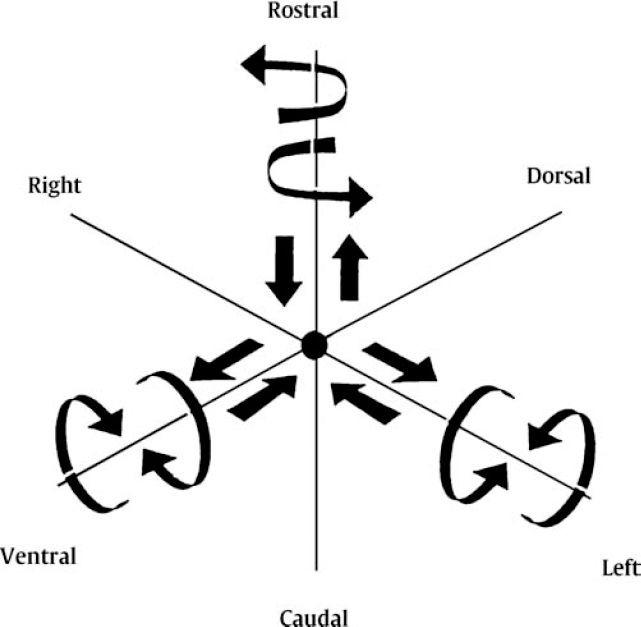
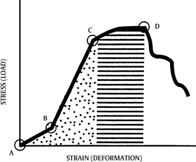
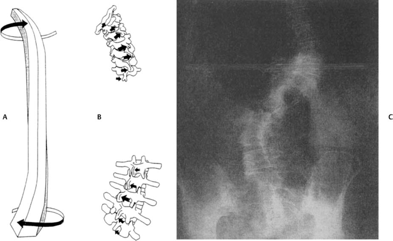
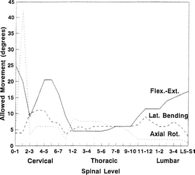
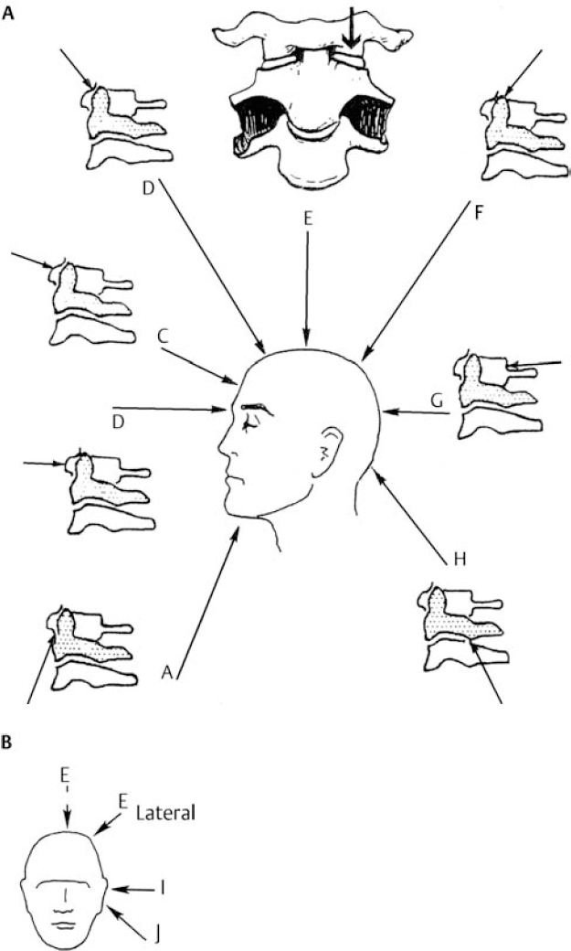
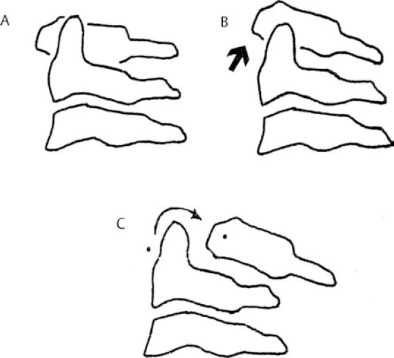
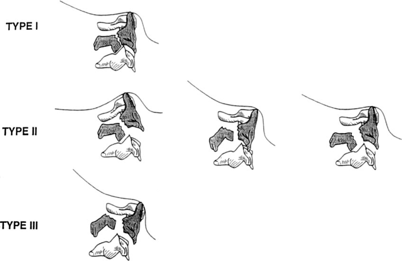
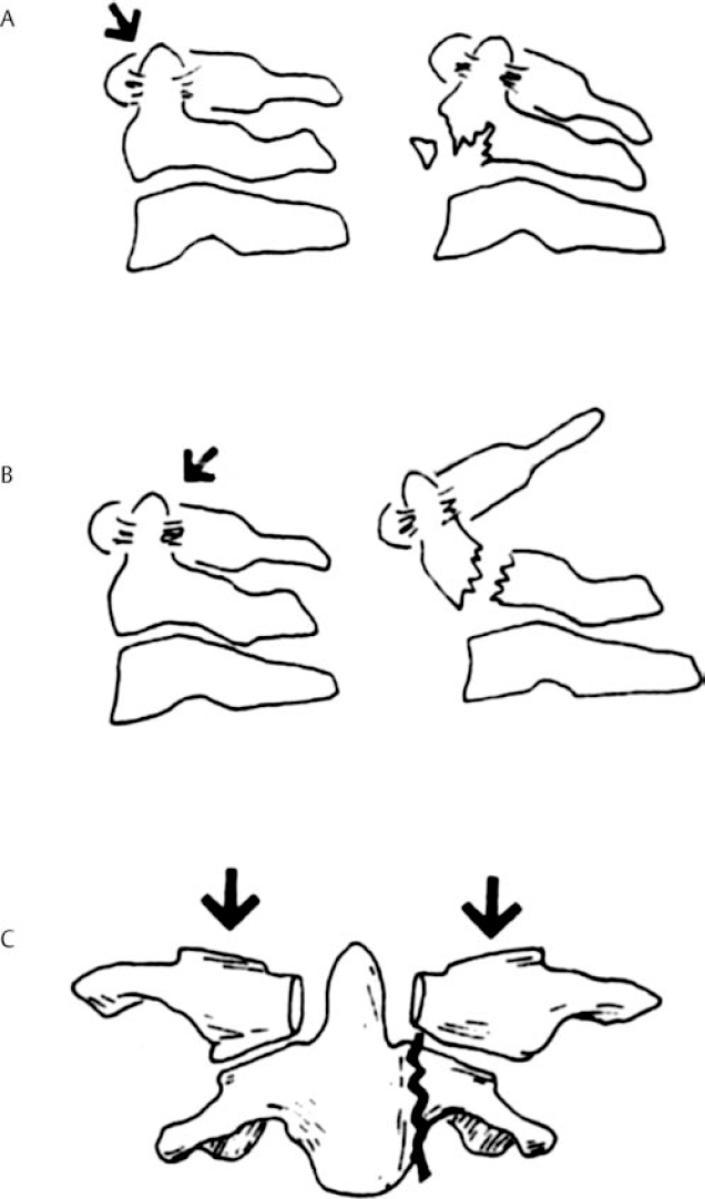
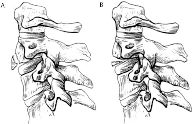
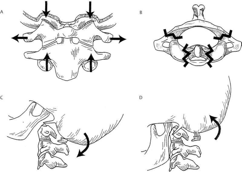
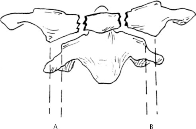
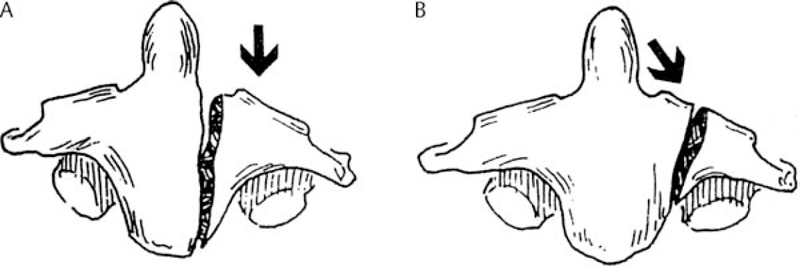
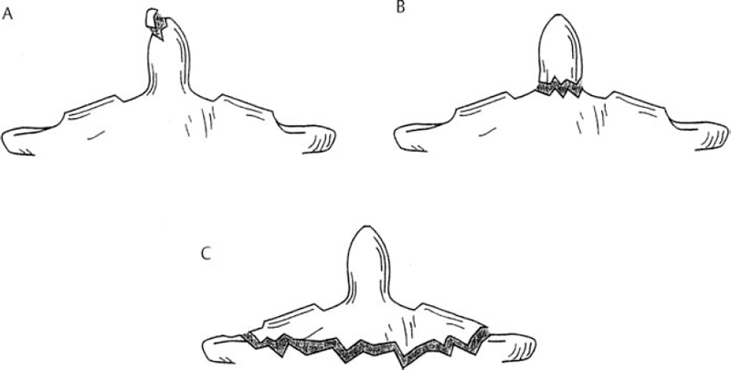
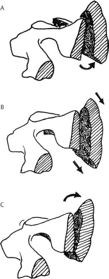
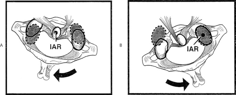
6 Biomechanics of the Spine Eve C. Tsai, Eric P. Roger, and Edward C Benzel The discipline of biomechanics embodies the application of the principles of physics to biologic systems. A basic understanding of the anatomy and of biomechanical principles facilitates a better understanding of spine injury and its effect on the normal function of the human vertebral column. Detailed anatomy is dealt with elsewhere in this text. This chapter defines some of the terms and principles used in clinical spinal biomechanics and illustrates how these biomechanical principles apply to spine injury in general. The biomechanical principles with respect to some of the most common and illustrative types of traumatic spine injury are discussed here. Fig. 6.1 The Cartesian coordinate system with the instantaneous axis of rotation as the center. Translation and rotation can occur in both of their respective directions about each axis. (From Benzel EC, ed. Biomechanics of Spine Stabilization. New York: Thieme; 2001:20, with permission.) A scalar is a quantity of magnitude and does not have a direction. When direction is given to a magnitude, it is then termed a vector. An action that changes the state of rest of the body to which it is applied can be defined as a force. Because force has no direction, it is a scalar. If a force has a direction, it is called a force vector or load vector. Force and load are used interchangeably in biomechanics. When a force vector acts on a lever (moment arm), it causes a bending moment. When a bending moment is applied to a point in space, it causes rotation, or a tendency to rotate about an axis. This axis regarding the spine is termed the instantaneous axis of rotation (IAR). The moment arm (M) is equal to the force (F) multiplied by its perpendicular distance (D) from the IAR (M = F × D). Therefore, the moment arm increases when the same force is applied farther away from the IAR. The standard Cartesian coordinate system has been applied to the spine (Fig. 6.1). In this system, there are three axes: x, y, and z. Applied clinically, these axes can also be described by rostral-caudal, ventral-dorsal, and right-left. Rotational and translation movements can occur within these axes. Therefore, there are 12 potential movements about the IAR, as there are two translational movements (in each direction) along each of the three axes and two rotational movements (one in each direction) around each of the axes. With this coordinate system, all force vectors can be divided into their components and hence facilitate systematic study. A deforming force vector results in strains. The deforming force vector can be translational or rotational. With a translational deforming force vector, there is a change in the length of the body. With a rotational deforming force vector, there is a change in the angle of the body. Strain is the change in the body when a deforming force vector is applied to the body. A linear strain is the change in unit length, and a shear strain is the change in unit angle. When a deformation occurs in the direction of the force application, it is termed axial strain. When a deformation occurs transverse to the direction of the application of the force, it is termed transverse strain. The application of a force vector or stress to the spine results in deformations or strains, as no solid is absolutely rigid. With respect to biologic systems, the stress/strain curve (Fig. 6.2) can be divided into different zones. Initially, when a force is applied to a biologic tissue in vivo, most solids (e.g., bones) subjected to the external force are buffered from the force by ligaments, disks, tendons, and other soft tissues. Therefore, the first zone that is passed is the neutral zone. Once the maximum strain capacity of the neutral zone is reached, the tissues are then deformed according to Hooke’s law, where the size of the deformation is proportional to the deforming force and applies to small displacements. Once deformation ensues, the stress/strain relationship enters the elastic zone. In the elastic zone, the tissue completely recovers when the strain is removed. The magnitude of the elastic zone is dependent on the elastic modulus of the tissue, and thus is obviously greater for ligaments than bone. With further application of force, the elastic zone is exceeded, and the elastic limit (or yield point) is reached. At this point the relationship between stress (force) and strain (extent of deformation) is no longer linear. With even more application of force, the elastic limit is exceeded. The plastic zone is thus entered. In this zone, the tissue acquires a permanent set so that if the external forces are removed, the solid does not spring back to its undeformed configuration. With the continued further application of force, the tissue will fail, thus reaching the failure point. After damage has occurred, the segment is relatively lax, with an expanded neutral zone. This increase in the neutral zone defines, in part, segmental instability. The ratio of stress to strain defines stiffness (Fig. 6.2). In the spine, the relationship between stress and strain is not always linear. Therefore, to determine the maximum stiffness or elastic modulus of a structure, the most linear portion of the stress/strain curve is often selected. Flexibility is the inverse of stiffness, or the ratio of the strain to an applied stress. Range of motion is a term that is frequently used in spine biomechanics. It describes the deformation, from one extreme to the other extreme, within the confines of the neutral and elastic zones of an intervertebral joint. The area under the stress/strain curve defines the energy absorbed prior to failure and is a measure of strength. The area under the curve up to the yield point is a measure of an object’s resilience. The phenomenon of coupling, as it relates to the spine, is defined as a movement of the spine along or about an axis, which obligates another movement along or about another axis (of the Cartesian coordinate system). For example, when the cervical spine bends laterally, there exists an obligatory rotation of the spinous processes away from the concave side of the curve. This is due to the orientation of the facet joints and the presence of the uncovertebral joints (Fig. 6.3). In the lumbar spine, because of the different orientation of the lumbar facet joints (sagittal rather than coronal, as is the case in the cervical spine), the spinous processes rotate in the same direction as the concave side of the lateral bend. Fig. 6.2 A typical stress/strain curve for a biologic tissue, such as a ligament. Point A to point B is the neutral zone, and B to C is the elastic zone. When the elastic limit (yield point, C) is reached, permanent deformation can occur (permanent set). Point C to point D is the plastic zone, where a permanent set occurs. Past point D, failure occurs, and the load diminishes. Hashed plus dotted area represents strength, whereas the dotted area represents resilience. (From Benzel EC, ed. Biomechanics of Spine Stabilization. New York: Thieme; 2001:24, with permission.) The type of spine injury that occurs following trauma is influenced by the structural anatomy and the force vector(s) applied. Facet orientation, bony anatomy, associated ligaments, and supporting structures (e.g., the rib cage) generally affect the segmental motions that occur at the various spinal levels (Fig. 6.4). The anatomical effects can be illustrated by the example of the occipital-C1 facet. Because of the obliquity of the occipital-C1 facets and because the occipital condyles are medial to the superior articulating facets of C1, the ring of C1 is prone to injury from axial loading. The location of the dorsal arch of C1 can be injured with hyperextension and hyperflexion loading injuries. In general, flexion and extension are most prominent in the cervical and lumbar spine, and rotation is greatest in the atlantoaxial joint and to a lesser extent in the thoracic spine (Fig. 6.5). In the cervical spine, pathologic stresses are increased by the substantial force vectors that are often applied during head trauma or with sudden deceleration of the torso. It has been reported that many upper cervical spine injuries result from trauma to the head.1-6 As well, sudden deceleration of the torso, combined with restriction of movement of the cervical spine, can create a flexion-distraction mechanism of injury, which is a result of a torso deceleration-induced cervical spine-bending moment. When a force vector is applied to the spine, the kinetic energy imparted is dissipated by the vertebrae and the surrounding spinal elements, which include the ligaments and calvarium. The kinetic energy imparted by the force vector dictates the magnitude of the injury; however, the relative strengths of the spine and the spinal elements influence the injury type. For example, when an axial load is applied to the cervical spine, a burst fracture of the atlas, a C2 burst-pedicle fracture, or a subaxial cervical spine burst fracture can result. The relative intrinsic strengths of the ring of C1, the body and pedicle of C2, and the subaxial cervical spine vertebral bodies affect the type of injury that follows a failure-producing force. More commonly, C1 or the subaxial spine is a relatively “weak link,” so a C1 burst fracture or a subaxial spine fracture is common. Fractures of C2 or the calvarium and occipital condyles, however, can also occur. Fig. 6.3 An important manifestation of the coupling phenomenon is the relationship between lateral bending and rotation in the cervical and lumbar regions. This is depicted (A) diagrammatically and (B) anatomically. Note that the coupling phenomenon results in spinal rotation, in opposite directions, in these two regions. (C) A biconcave thoracic and lumbar curve, as depicted in an anteroposterior view, illustrates this phenomenon. Note that the lumbar spinous processes are rotated toward the concave side of the curve. (From Benzel EC, ed. Biomechanics of Spine Stabilization. New York: Thieme; 2001:28, with permission.) Fig. 6.4 Segmental motions allowed at the various spinal levels (combined flexion and extension, solid line; unilateral lateral bending, dashed line; and unilateral axial rotation, dotted line). (From Benzel EC, ed. Biomechanics of Spine Stabilization. New York: Thieme; 2001:4, with permission.) This section addresses the principles of biomechanics with respect to some of the more common spine injuries, beginning with the occipital cervical complex and proceeding downward to the subaxial spine and sacrum. Because the anatomy of the subaxial spine, to the sacrum, is relatively similar, subaxial injuries are grouped together. Sacral injuries are discussed separately. Fig. 6.5 The mechanism of injury (orientation of injury force vector) partly dictates the type of injury incurred. (A) Sagittal plane injury. (B) Coronal plane injury. (From Benzel EC, ed. Biomechanics of Spine Stabilization. New York: Thieme; 2001:64, with permission.) Fig. 6.6 The mechanism of injury of a dorsal C1-C2 dislocation. Note the requirement for at least some distraction (heavy straight arrow) to cause the ventral arch of C1 to slide over the dens (curved arrow). Dots portray original (pretraumatic) and posttraumatic ventral C1 arch location. (From Benzel EC, ed. Biomechanics of Spine Stabilization. New York: Thieme; 2001:64, with permission.) Comprehension of the direction of the force vector that is applied to the occipital-cervical region aids in the understanding of the fracture patterns that occur. The common fracture patterns are discussed here, beginning with a rostral extension-oriented force vector and proceeding sequentially to other common, clinically relevant, orientations of force vectors, as illustrated in Fig. 6.5. With a rostral-dorsal or rostral-extension-oriented force vector (Fig. 6.5, injury mechanism A), a judicial hangman’s fracture or, less commonly, a dorsal dislocation of C1 on C2 can occur. The judicial hangman’s fracture (bilateral pars interarticularis fracture) of C2, with or without ventral subluxation, results from judicial hanging with the noose placed in the submental position. Other injury types, such as falls7,8 and the use of a diagonal shoulder harness without an accompanying lap belt,9 can cause this type of injury. Rostral-dorsal-oriented force vectors can also cause dorsal C1-C2 dislocations.10,11 In this situation, the force vector causes the ventral arch of C1 to sublux over the dens, resulting in locking the C1 ring behind the dens (Fig. 6.6). A dorsal- or extension-oriented force vector applied to the head can cause the commonly occurring hangman’s fracture or traumatic spondylolisthesis of the axis (Fig. 6.5, injury mechanism B) from bilateral C2 pars interarticularis fractures. Hangman’s fractures have been classified by Effendi into three types3 (Fig. 6.7). A dorsal-oriented force vector is associated with the Effendi type I fracture. The type I fracture is the most common and is an isolated hairline fracture of the pars interarticularis with less than 3 mm displacement between the dorsal dens and the dorsal body of C3. Fig. 6.7 The Effendi classification of hangman’s fractures. A type I fracture is an isolated hairline fracture of the pars interarticularis with minimum displacement of the body of C2 on C3. A type II fracture involves the ventral displacement of the ventral fragment (C1 and C2 body) on C3. A type III fracture involves the ventral displacement as with type II fractures, but with the body of C2 resting in a flexed position. (From Benzel EC, ed. Biomechanics of Spine Stabilization. New York: Thieme; 2001:65, with permission.) When there exists a dorsal force vector, combined with a small axial load (Fig. 6.5, injury mechanism C), an Effendi type II fracture may occur. With the type II fracture, there is a greater than 3 mm displacement between the posterior dens and the posterior C3 body or angulation of C2 on C3, indicating potential disruption of the posterior longitudinal ligament and disk. The type II fracture also has a flexion force applied after the initial extension force. With the type III fractures, the facets of C2-C3 are bilaterally locked. These fractures are relatively rare and, unlike type I and type II fractures, involve a flexion compression mechanism. Dorsal force vectors, combined with axial force vectors, can also cause other, more common fractures of C2. When the bony fault travels through the pedicle and the dorsal C2 vertebral body, it is termed a vertical coronally oriented C2 body fracture with C2-C3 subluxation (Fig. 6.8). When the dorsal force vector is applied to the high forehead region (Fig. 6.5, injury mechanism D), capital hyperextension forces, together with an axial load force, can be applied to the cervical spine. In this case, the fracture fault can pass through the ventral caudal aspect of the C2 body, resulting in a teardrop avulsion fracture, and through the ventral disk interspace between C2 and C3 and the dorsal C2 vertebral body (Fig. 6.9). This fracture is termed a dorsal C2 body fracture with C2-C3 subluxation and a ventral teardrop. Other variants include the isolated extension teardrop and hyperextension dislocation injuries (Fig. 6.9). The isolated extension teardrop fracture involves an avulsion injury of the ventral caudal aspect of the C2 vertebral body. If extension results in C2-C3 disk interspace disruption, a hyperextension dislocation injury results. Both of these variants are termed horizontal caudal C2 body fractures. Axial loads applied to the cranial vertex (Fig. 6.5, injury mechanism E) can cause several injury types, depending on the relative strengths of the vertebral elements. Although occipital condyle fractures can also occur with axial loading, they are much less common than C1 fractures because the ring of C1 is relatively weak, compared with the occiput. Three types of occipital condyle fractures have been identified. Types I and II occur with axial loading. Type I fractures involve a medial disruption of the condyle and are rare, because the ring of C1 usually fails before the occipital condyle. With type II occipital condyle fractures, the fracture is usually an extension of a basal skull fracture. Type III occipital condyle fractures are more frequently associated with laterally directed force vectors and are discussed later in the chapter. The most commonly occurring fracture in the upper cervical spine is the C1 burst fracture (Jefferson fracture) (Fig. 6.10). The oblique orientation of the occipital C1 facet joints results in a laterally directed force with axial compression that results in a fracture of the C1 ring. This causes a C1 burst fracture (Jefferson fracture). Axial loads, with or without hyperextension, can result in C1 arch fractures, usually through the weakest point of the atlas. This is usually near the course of the vertebral artery. Axial loads with a component of hyperextension or hyperflexion moment application via ligamentous attachments to C1 may also result in C1 arch fractures. Fig. 6.8 Blows to the head cause an extension load (A) or a flexion load (B) to be applied to the odontoid process, unless a pure axial load is applied. If a pure axial load is applied, the lateral masses bear this load. A C2 fracture may result (C). (From Benzel EC, ed. Biomechanics of Spine Stabilization. New York: Thieme; 2001:63, with permission.) Fig. 6.9 The mechanism of injury of type I C2 body fracture variants. (A) Isolated extension teardrop fracture. (B) Hyperextension dislocation. (From Burke JT, Harris JH. Acute Injuries of the Axis Vertebra. Skeletal Radiol 1989;18:335–346, with permission.) To assess stability and the possible rupture of the transverse ligament of the atlas, the total lateral displacement of the C1 facet joints on C2 (summation of the total lateral displacement on both the right and left side) can be determined from an anteroposterior plain radiograph. A sum greater than 7 mm indicates that the fracture may be unstable (Fig. 6.11 ).12 Although plain radiographs may be useful for screening, they may be misleading, and computed tomography (CT) and magnetic resonance imaging (MRI) may be more helpful regarding the assessment of the stability of an injury. Two types of transverse ligament injuries associated with C1 fractures have been identified. With type 1, the transverse ligament injury is ligamentous, whereas the type 2 injury is associated with an avulsion of the transverse ligament from its attachment to the bony ring of C1. With type 1 ligamentous injuries, surgery may be required to maintain stability, whereas with type 2 injuries, surgery may not be required, because stability can be achieved with fracture healing. It should be noted that the mechanism of injury is controversial.13 C2 body fractures may also occur if other structures, such as the occipital condyle, C1, or subaxial spine fractures do not occur first. With axial loads to the articular pillars of C2, comminuted sagittal fractures of the lateral aspect of the C2 body can occur. With this injury, the dorsal wall of the C2 vertebral body is thrust into the spinal canal. Technically, this fracture can be considered a burst fracture via the Denis classification scheme.14 These vertical sagittally oriented C2 burst-pedicle fractures are best seen with an anteroposterior view. With purely axial loads, the compression is substantially borne by the facets. If an extension or flexion component, however, is added, a large portion of the load is borne by the odontoid process. In this case, the dens functions as a lever or moment arm by accepting the load and applying a bending moment. If a lateral component to the axial load is applied, the fracture may extend more laterally, passing through the foramina transversaria and along the pars interarticularis of C2 (Fig. 6.12). Fig. 6.10 (A) A coronal section of the C1-C2 articulations with surrounding elements. An axial load (vertical arrows) causes a laterally oriented resultant force vector (horizontal arrows) that, if substantial, causes (B) a bursting of the ring of C1 via fracture of the ring in four locations (Jefferson fracture). (C) Hyperextension of the calvarium can cause a fracture of the posterior arch of C1 by impingement on the dorsal arch of C1 via the occiput or the lamina of C2. (D) Hyperflexion can cause a similar injury via ligamentous attachments. The latter two injuries do not usually degrade spinal stability, as can the C1 burst fracture. (From Benzel EC, ed. Biomechanics of Spine Stabilization. New York: Thieme; 2001:62, with permission.) Fig. 6.11 A greater than 7 mm lateral displacement of the C1 facet on the C2 facet, adding the (A) right and (B) left displacements, implies disruption of the transverse ligament of the atlas and significant instability. (From Benzel EC, ed. Biomechanics of Spine Stabilization. New York: Thieme; 2001:66, with permission.) Ventrally applied force vectors with an axial component (Fig. 6.5, injury mechanism F) may result in a dorsal caudal C2 teardrop fracture with flexion and opening of the C2-C3 disk space. The orientation of the C2-C3 disk space is in line with the applied-force vector. This results in a C2-C3 subluxation. This vertical coronally oriented dorsal C2 body teardrop fracture with C2-C3 flexionsubluxation fracture may occasionally extend rostrally into the dens, or an isolated vertical dens fracture can occur. The latter fracture may be the result of the ventral foramen magnum impinging upon the dens as a result of the applied axial load. A ventrally oriented force vector applied to the dorsal aspect of the head (Fig. 6.5, injury mechanism G) can result in true neck flexion and may injure C2 or the transverse ligament of the axis. Fractures of C2 include a horizontal fracture through the rostral portion of the body of C2.5 This has been classified by Anderson and D’Alonzo15 as a type III odontoid process fracture, although technically the fracture is located in the vertebral body of C2 and not the odontoid16,17 (Fig. 6.13C). The complete classification of “odontoid” fractures is shown in Fig. 6.13. In children, ventral force vectors do not commonly cause C2 fractures. Such vectors tend to cause fractures or, rather, failure through the synchondroses or ossification centers. If the dens does not yield to a failure-producing force, the transverse ligament may rupture. The ligament, however, is usually stronger than C2, so transverse ligament rupture is less common. MRI may aid in the demonstration of the transverse ligament disruption. Fig. 6.12 The mechanism of injury of a vertical sagittally oriented C2 burst-pedicle fracture. (A) Note the absence of bony support immediately below the lateral mass of C2 (shaded area). (B) A more lateral orientation of the axial load (see Fig. 6.5) may result in a more laterally situated fracture. (From Benzel EC, ed. Biomechanics of Spine Stabilization. New York: Thieme; 2001:67, with permission.) Fig. 6.13 The Anderson and D’Alonzo odontoid process fracture scheme. (A) A type I dens avulsion fracture. (B) A type II dens base fracture. (C) A type III horizontal upper C2 body fracture. (From Benzel EC, ed. Biomechanics of Spine Stabilization. New York: Thieme; 2001:68, with permission.) A ventral force vector with distraction (Fig. 6.5, injury mechanism H) is usually caused by deceleration over a fulcrum, such as over a shoulder harness. A flexion-distraction force is applied and can result in the application of a bending moment about the ventral caudal aspect of C2, with an accompanying opening of the disk interspace dorsally and the maintenance or exaggeration of disk height and the preservation of ventral soft tissue integrity. This fracture is termed a vertical coronally oriented dorsal C2 body fracture. It results from the application of flexion-distraction forces and has been termed an atypical hangman’s fracture.18 This atypical fracture can be caused by other mechanisms, including hyperextension with an axial load, hyperflexion with an axial load, and flexion-distraction (Fig. 6.14). Laterally directed force vectors19 (Fig. 6.5, injury mechanism I), with or without extension,20 can cause type II odontoid or dens fractures. Lateral force vectors can also result in type III occipital condyle fractures, in which an avulsion injury is caused by shearing forces that place tension on the occipital condyle via the alar and capsular ligaments.17,21 Other injuries may also be associated, including open upper cervical injuries22 and tectorial membrane injuries, particularly in children.23 Fig. 6.14 Various mechanisms of injury of vertical coronally oriented C2 body fractures. (A) Hyperextension with varying degrees of axial loading (see Fig. 6.5A, injury mechanisms C and D), resulting in a bending moment (arrow). (B) Axial loading with some flexion (see Fig. 6.5A, injury mechanism F), resulting in a translational deformation (arrows). (C) Flexion-distraction (see Fig. 6.5A, injury mechanism H), resulting in a bending moment (arrow). (From Benzel EC, ed. Biomechanics of Spine Stabilization. New York: Thieme; 2001:69, with permission.) An applied lateral bending rotation-distraction force complex (Fig. 6.5, injury mechanism J) may result from lateral deceleration injuries. Atlanto-occipital dislocation has been attributed to the application of this force complex, although hyperextension-distraction mechanisms have also been postulated.1,24 If a torque is applied about the long axis of the spine or dens, a rotatory injury may result.25,26 The rotatory subluxation of C1 on C2 occurs because this region is the weakest link in the occiput-C1-C2 ligamentous complex. If the IAR is situated more laterally (e.g., through the facet joint), it may result in a contralateral unilateral rotatory subluxation (Fig. 6.15). The biomechanical studies of Mouradian and colleagues5 and Fielding and colleagues27 have provided much of the evidence for the aforementioned statements. Their observations are summarized in Fig. 6.16. Whereas the considerable variation in anatomy of the upper cervical spine results in many complex patterns of injury, the anatomy of the subaxial spine is more consistent. As a result, the injury patterns are less varied. Therefore, they are examined as a group. Like the occipital-cervical region, subaxial spine injury is also determined by force vectors. The magnitude of the force vector must be great enough to reach the failure point and cause injury. The magnitude can be influenced by the bending moment. The bending moment is the result of a force vector on a lever. When the same force is applied to a long lever compared with a short lever, the resulting force is greater in magnitude. Because the perpendicular distance of force application in relation to the IAR determines the length of the lever arm (moment arm), the bending moment can be significantly affected by the location of the point of force vector application in relation to the IAR. The direction of the force vector affects the fracture pattern. For example, compressive forces that are applied ventral to the IAR often result in wedge compression fractures. Pure axial loading (i.e., in line with the IAR) results in a pure burst fracture. Distraction forces placed dorsal to the IAR result in a ligamentous or bony Chance fracture, whereas a compressive force in that same area (behind the IAR) results in hyperextension-shear injuries. Ventral wedge compression fractures that are generated from an axial load placed ventral to the IAR create a ventrally oriented bending moment. In this situation, all elements of the spine that are located ventral to the IAR become closer together, and all the elements dorsal to the IAR become farther apart. Dorsal distraction is not significant because of the resistance of the dorsal ligamentous complex. At the ventral/dorsal plane of the IAR, the vertebral body height is unchanged. The bending moment causes an eccentric loading of the spine and concentrates the stresses ventrally. This increased stress concentration ventrally explains why failure is more likely when a bending moment is simultaneously applied with an axial load (Fig. 6.17). This contrasts with burst fractures (see below). Imaging demonstrates the flexion deformity where the ventral vertebral body height is less than the dorsal height.1,28–31
 Biomechanical Principles and Terms
 Clinical Biomechanics and General Principles
 Biomechanics and Specific Spine Injuries
Occipital-Cervical Spine Injuries
Superior-Dorsal-Oriented Force Vector
Dorsal-Oriented Force Vector
Dorsal with Axial Load Force Vector
Axial Force Vectors
Ventral Force Vectors
Ventral Force Vector with Distraction
Laterally Directed Force Vectors
Lateral Bending Rotation-Distraction Force
Torque
Subaxial Spine
Axial Force Vectors Ventral to the Instantaneous Axis of Rotation: Ventral Wedge Compression Fractures
Biomechanics of the Spine
Only gold members can continue reading. Log In or Register to continue

Full access? Get Clinical Tree


