Vacuum-insulated evaporator
Nitrous oxide supply
Nitrous oxide is supplied from a central bank of gas cylinders, which contain a mixture of liquid and gas (critical temperature of nitrous oxide is 36.5 °C). These are connected to the distribution pipeline network by a control panel, which regulates the gas pressure. The control may also provide local heating in order to avoid condensation and freezing due to the cooling caused by the evaporation of the liquid nitrous oxide. A reserve bank of cylinders is also provided.
Medical compressed air
Compressed air for medical use must be much purer than its industrial equivalent. It is generated by compressors and will contain oil mist as well as water vapour. In a hospital two types of supply are required, a low-pressure supply (420 kPa) for anaesthetic machines and ventilators, and a higher-pressure supply (700 kPa) to provide power for surgical equipment. The pipeline network may be supplied either by a bank of air cylinders or by a local compressor system. If a local compressor is used care must be taken to ensure the purity of the compressed air produced.
Medical vacuum
Medical vacuum is required for suction, and BS4957 specifications suggest a vacuum level of 53 kPa (400 mmHg). Medical vacuum is also required for scavenging of anaesthetic gases, but it is not recommended that the same vacuum supply is used for both purposes because:
Suction requires relatively low flow rates but high levels of vacuum, which if applied inadvertently to a patient’s airway would be harmful.
Scavenging requires low vacuum levels with high flow rates. The high flow rates used to remove waste anaesthetic gases could reduce suction levels during surgery.
Waste anaesthetic gases contain volatile vapours which may be absorbed by lubricants and ultimately cause system failure.
Suction vacuum systems incorporate bacterial filtration and drainage to dispose of aspirated body fluids.
Gas cylinders
Gases and vapours are supplied from cylinders in the absence or failure of piped gas supplies. The cylinders are made of molybdenum steel, which is stronger than carbon steel. This enables cylinders to be made with thinner walls and therefore lighter in weight. They are used to supply the gases and vapours shown in Figure 46.2.
| Content | Gas/vapour | Cylinder pressure kPa (psi) | Boiling point at 1 atm (°C) | Critical temperature (°C) |
|---|---|---|---|---|
| Oxygen | gas | 13,700 (1980) | – 183 | – 118 |
| Nitrous oxide | vapour | 4400 (640) | – 89 | 36.5 |
| Entonox | gas and vapour | 13,700 (1980) | gas separation at – 6 °C | |
| Air | gas | 13,700 (1980) | ||
| Carbon dioxide | vapour | 5000 (723) | – 78.5 | 31 |
| Helium | gas | 13,700 (1980) | – 269 | – 268 |
Cylinder identification
Cylinders are identified visually by a symbol and colour coding, as listed in Figure 46.3. They also have markings on them and labels giving information about their contents.
| Substance | Gas/vapour | Symbol | Colour coding | |
|---|---|---|---|---|
| Cylinder | Shoulder | |||
| Oxygen | gas | O2 | black | white |
| Nitrous oxide | vapour | N2O | blue | blue |
| Entonox | gas and vapour | N2O/O2 | blue | white/blue |
| Air | gas | AIR | black | white/black |
| Carbon dioxide | vapour | CO2 | grey | grey |
| Helium | gas | He | brown | brown |
Tare weight of cylinder
Hydraulic test pressure of cylinder
Identity of gas (symbol)
Density of gas
Serial number of cylinder
Owner of cylinder and manufacturer of gases
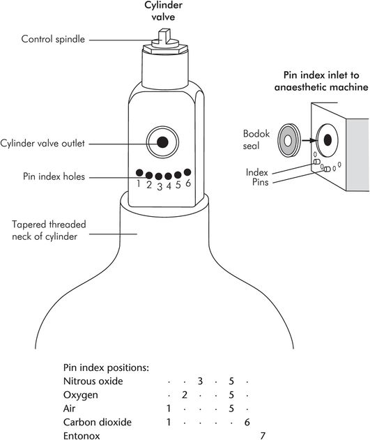
Pin index system (PIS)
Gas cylinders are also identified mechanically by a pin indexing system, which conforms to both British Standard (BS) and equivalent International Organization for Standardization (ISO) specifications. This system prevents the wrong cylinder from being connected to an anaesthetic machine.
The pin index system is designed into the outlet valve block of the cylinder, and is illustrated in Figure 46.4. The cylinder valve block face matches up to the inlet port of the anaesthetic machine. This face contains the gas outlet from the cylinder, which is made gas-tight by a metal and rubber ring seal, the Bodok seal. Beneath the outlet are six possible positions for indexing holes. Pins on the anaesthetic machine inlet fit into these holes. If the positions of these pins do not match the index holes on the valve block outlet, the cylinder cannot be fitted to that particular inlet on the anaesthetic machine. Figure 46.4 shows PIS positions for some of the gases commonly used, and details of the cylinder head arrangement.
Cylinder testing
Cylinders are hydraulically tested every 5 years using water under high pressure. Water or water vapour remaining in a cylinder may represent a hazard because it may condense and freeze (affecting the operation of the outlet valve) if the cylinder empties rapidly. Random cylinders from a batch may be destructively tested by the manufacturers using water under pressure.
Cylinders are inspected by the manufacturer endoscopically for cracks and defects on their inner surfaces, and they can also be tested ultrasonically.
Estimation of cylinder contents
The contents of a cylinder, for both gases and vapours, are estimated by weighing the cylinder and subtracting the weight of the empty cylinder or tare weight, which is recorded on the cylinder itself.
Cylinder sizes can be identified by a letter (BOC coding) according to internal volume (water capacity). A reserve oxygen cylinder on an anaesthetic machine may be an ‘E’ cylinder, with a water capacity of 4.7 litres. A tall standing cylinder with a side spindle pin index valve may be a ‘J’ cylinder, with a water capacity of 47 litres.
Gases
In the case of gases, such as oxygen and air, cylinders are initially filled to a given pressure (13,700 kPa = 137 bar). Since gases are not liquefied in the cylinder (temperature < critical temperature), the cylinder contents can also be estimated by the cylinder pressure. This gradually decreases as the cylinder empties. The mass of gas present is directly proportional to the pressure according to the universal gas law, and the volume of the contents available at atmospheric pressure can be estimated using Boyle’s law.
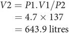
An ‘E’ cylinder has a water capacity of 4.7 litres (V1) and is filled to a pressure of 137 bar (P1). Its contents (V2 ) at atmospheric pressure (P2 = 1.0 bar) are given by Boyle’s law:
Vapours
In the case of vapours (such as nitrous oxide or carbon dioxide) the contents of the cylinders are a mixture of gas and liquid. The cylinders are initially filled to a given filling ratio. The filling ratio is defined as the weight of the substance contained divided by the weight of a volume of water equal to the internal volume of the cylinder. This ratio is set at 0.75, since if the cylinders are overfilled there is a risk of rupture with increases in ambient temperature.
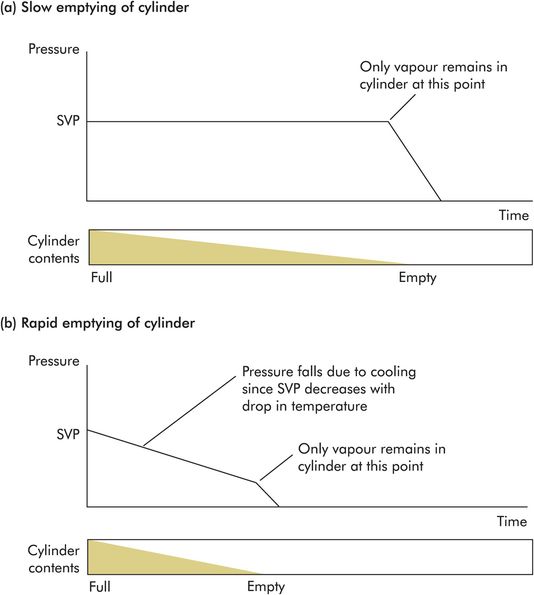
With vapours the cylinder pressure cannot be used to estimate cylinder contents, because it does not vary as the cylinder empties. This is because the cylinder pressure is maintained at saturated vapour pressure (SVP) while liquid is present. The cylinder pressure only falls when the cylinder is nearly empty and all of the liquid contents have evaporated.
Cylinder pressure, in the case of vapour content only, varies if the temperature changes. This can occur when the cylinder is emptied rapidly, due to absorption of latent heat of vaporisation causing cooling of the contents. Under these circumstances the cylinder pressure will decrease with cooling but will be restored as the cylinder warms up again (Figure 46.5).
Pressure regulators
The high pressure inside gas cylinders is reduced by a pressure regulator before connection to equipment such as an anaesthetic machine. An example of a single-stage regulator which might be used to reduce oxygen cylinder pressure from 13,700 kPa to 420 kPa is shown in Figure 46.6. Cylinder pressure (P) is reduced to the supply pressure (p) as oxygen passes through the small inlet valve (area = a) into the control chamber. The pressure in the control chamber (p) is controlled by a compression spring acting on a diaphragm (area = A) which is coupled mechanically to the inlet valve. The supply pressure is thus controlled by the force (F) in the spring. This can be expressed by the following equation:
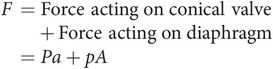
It is assumed that the force in the spring remains constant, i.e. the range of movement in the spring is small compared to its total length. Then any change in the supply or cylinder pressures will cause a compensating change as the diaphragm moves and varies the effective area of the inlet valve. In the above equation, if F is constant, a decrease in pA (drop in supply pressure due to increased demand) causes an increase in Pa (increased flow from cylinder). Alternatively if Pa decreases (due to cylinder pressure falling as it empties), pA will increase (increased flow from cylinder).
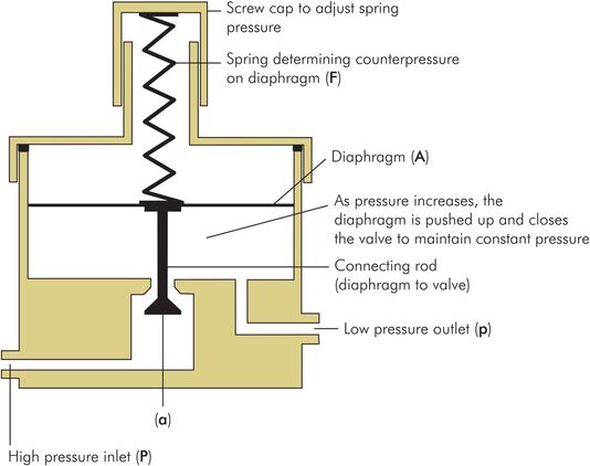
Single-stage pressure regulator
The pressure regulator reduces the cylinder pressure from 137 bar in an O2 cylinder, or 44 bar in an N2O cylinder, to a lower supply pressure of approximately 4 bar (400 kPa). It also compensates for changes in demand or cylinder pressure. The sensitivity of this control depends on the ratio of the area of the control-chamber diaphragm to the area of the conical valve, which is usually 200:1.
Anaesthetic machines
Surgical anaesthesia is usually provided through a continuous-flow anaesthetic machine which consists of the following components:
Metal framework and pipeline circuitry
Medical gas pipeline service connections
Connections for gas cylinders and pressure gauges for cylinder contents
Safety mechanisms
Back bar including vaporiser connections
Common gas outlet and auxiliary gas outlets
Vaporisers
Rotameters (see Gas flow measurement in anaesthetic machines in Chapter 45)
Scavenging circuitry
Suction circuitry
The basic arrangement of these components is illustrated in Figure 46.7. Modern machines often incorporate electronic monitoring, safety features and a mechanical ventilator.
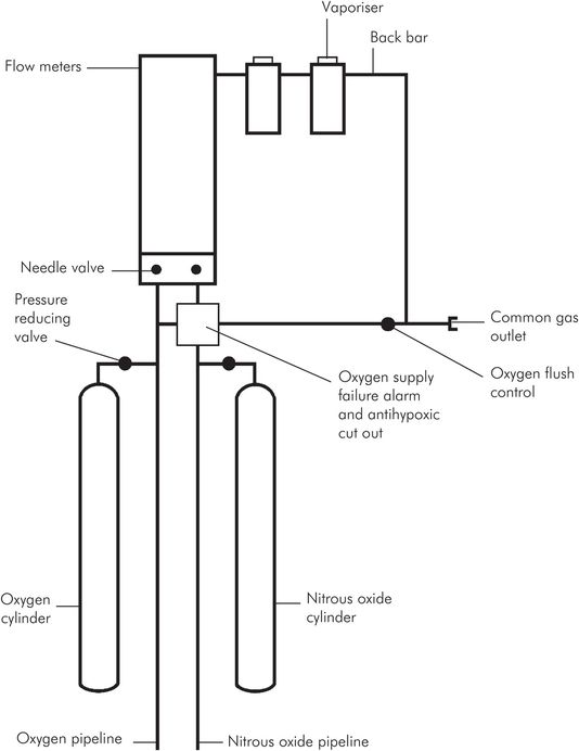
Basic components of an anaesthetic machine
Metal framework and pipeline circuitry
The metal framework of the anaesthetic machine is usually made of stainless steel and is electrically earthed via antistatic wheels, which reduce risks of electric shock, interference with rotameters, and fire or explosion of inflammable agents. The frame incorporates pipeline circuitry with both fixed and detachable joints. The pipes are usually brass or copper with brazed fixed joints. More recently nylon pipes have been introduced. Detachable joints are screw-threaded and sealed with a compressible washer, O-ring seal or polytetrafluoroethylene (PTFE) tape. Different diameter pipes are used for each gas to prevent cross-connection.
Medical gas pipeline service (MGPS) connections
Non-interchangeable screw-threaded (NIST) connections are used for MGPS supplies. Flexible colour-coded hoses are used to connect to gas-specific wall terminals. The machine end of these hoses is a male NIST.
NIST connectors are made gas-specific by:
A non-interchangeable threaded nut
A specific diameter shoulder with O-ring seal
A specific diameter forward shaft
The machine MGPS connections are the female counterparts of the above hose connectors. They also incorporate metal gauze filters and one-way non-return valves to prevent retrograde leakage.
Pin index system (PIS) connections for gas cylinders
The PIS connections for the cylinder gas supplies consist of a gas inlet with the male counterpart of the PIS, i.e. pins corresponding to the indexing holes on the cylinder valve block. A yoke with an arrangement secured by a screw fitting holds the cylinder valve block in place. The cylinder inlets also incorporate metal gauze filters and one-way non-return valves to prevent retrograde leakage. Retrograde leakage through gas inlets, if great enough, has been known to alter the gas mixture delivered to the patient, and can lead to the delivery of a hypoxic mixture. The PIS connection is made gas-tight by a metal and rubber ring seal in the cylinder valve block (Bodok seal). Pin index positions have been described in Figure 46.4.
Safety mechanisms
Several safety mechanisms are incorporated into the design of an anaesthetic machine. These include:
Secondary pressure regulators – Smooth out gas pressure fluctuations within the anaesthetic machine, which occur due to changes in pipeline pressure or variations in demand from the machine. Such fluctuations in machine pressure can cause inaccuracies in the fresh gas mixture, or disturb the performance of rotameters and oxygen monitors. Secondary pressure regulators are set to pressures below the anticipated pressure fluctuations and are designed to maintain working pressures within 10% over a wide range of flow rates, from hundreds of millilitres to tens of litres.
Oxygen failure warning device – Monitoring of the delivered fresh gas oxygen concentration is mandatory, but the anaesthetic machine also has a built-in oxygen failure device. This is mounted upstream of the rotameter block and is designed according to BS4272 specifications, which include:
Audible alarm > 60 dB at a distance of 1 metre from the machine, for 7 seconds or more
Activation when the oxygen supply falls to 200 kPa
Power supply derived from the oxygen supply pressure
Alarm that cannot be switched off or reset until the oxygen supply is restored
Alarm coupled to a gas cutoff valve that cuts off anaesthetic gases and opens the machine pipeline circuitry to air
An early oxygen failure warning device was the Ritchie whistle (1960), and many modern devices are similar in principle. Figure 46.8 shows how such a device works.
Oxygen bypass circuit – Bypasses the rotameter block and back bar to provide an emergency oxygen flow of at least 30 litres per minute to the common gas outlet. The control is usually a push-button situated near the common gas outlet, which is recessed to prevent accidental operation, and which cannot be locked, to prevent barotrauma to the patient.
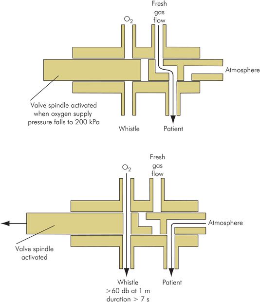
Oxygen failure warning device (Ritchie whistle)
Back bar
The back bar is the horizontal part of the anaesthetic machine circuit between the rotameter block and the common gas outlet. It is downstream of the rotameter block and feeds fresh gas mixture to the common gas outlet. Vaporisers are mounted on the back bar, enabling volatile agents to be added to the fresh gases. The pressure in the back bar is approximately 1 kPa at the outlet end, and may be 7–10 kPa at the rotameter end, depending on:
Total gas flow
Circuit connection to common gas outlet
Vaporisers used and their settings
Total occlusion of the common gas outlet produces pressures of approximately 30 kPa in the back bar. The maximum pressure that can be produced in the back bar is limited by a ‘blow off’ or pressure relief valve at the outlet end (threshold set to 30–40 kPa). This protects the rotameter block and vaporisers from overpressure damage, and to a very limited degree protects the patient from barotrauma.
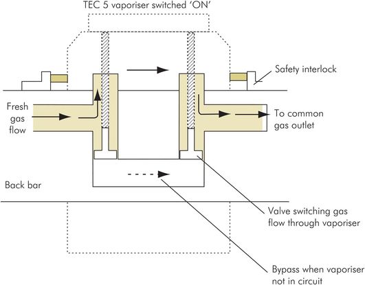
Vaporiser connections
The system for connecting vaporisers to the anaesthetic machine back bar is designed with specific features.
Vaporiser connections to the back bar
Prevent gas leakage from the back bar with or without a vaporiser in place
Prevent volatile agent leakage into the back-bar circuit
Allow convenient installation and removal of vaporisers
Have a safety interlock mechanism to prevent use of more than one volatile agent simultaneously
Figure 46.9 illustrates some of these design features. The potential hazards caused by poor design or usage of the vaporiser connection system include:
Leakage of gas, causing inadequate fresh gas mixtures or pressures to be delivered to the patient
Leakage of volatile agent into the fresh gas flow
Damage or injury caused by difficulty in attaching or detaching vaporisers
Contamination of downstream vaporisers by upstream volatile agent, when no safety interlock mechanism is present
Contamination of soda lime in the breathing circuit by trichloroethylene (no longer used in the UK), which produces a neurotoxin
In early machines, where more than one vaporiser could be switched on at a time, a more volatile agent (e.g. halothane), if placed upstream, could be absorbed by a less volatile agent (e.g. trichloroethylene). This could lead to the release of a maximal concentration (determined by the saturated vapour pressure) of the absorbed agent on subsequent use of the downstream vaporiser. In modern machines with a good safety interlock mechanism, the sequence of vaporisers on the back bar presents no significant hazard.
Vaporiser back-bar connections
Gas outlets
The common gas outlet is a 22 mm male (external) and 15 mm female (internal) tapered outlet which supplies fresh gas mixture to the patient breathing circuit or a mechanical ventilator. It may be mounted on a swivel (Cardiff swivel) for increased convenience. It can withstand bending moments of up to 10 Nm (equivalent approximately to 40–50 kg weight hanging from the outlet). It may be threaded to prevent accidental disconnection.
The auxiliary gas outlets are Schrader oxygen or air sockets, which can be used to power devices such as a ventilator or a Venturi injector.
Anaesthetic machine maintenance
Servicing of machines should follow the manufacturer’s guidelines. Typically servicing is performed at 3- to 6-month intervals. Each machine should have an attached log-book to record commissioning date, servicing dates, faults, repairs and modifications.
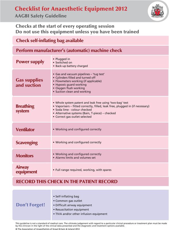
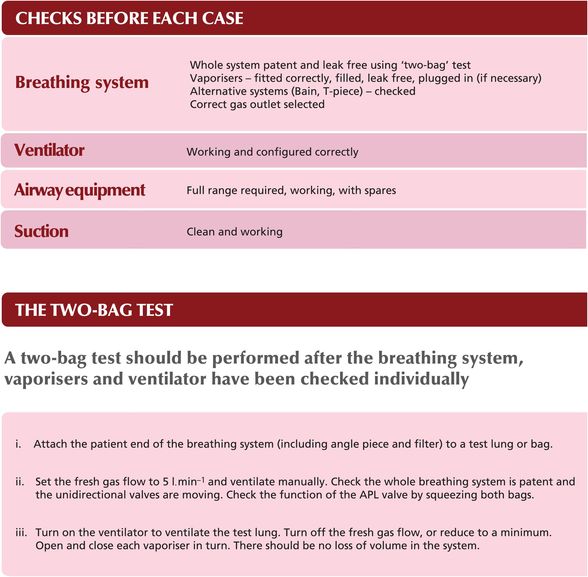
Anaesthetic machine checklist
The anaesthetic machine should be checked by the anaesthetist before each operating session. A checklist is published by the Association of Anaesthetists of Great Britain and Ireland (2012), designed to be attached to each machine (Figure 46.10).
Association of Anaesthetists of Great Britain and Ireland: checklist for anaesthetic equipment 2012.
Vaporisers
Functions of a vaporiser
To produce vaporisation of the volatile anaesthetic agent
To mix the vapour with the fresh gas flow to the patient
To control the mixture so that a given concentration of volatile agent is delivered to the patient, in spite of varying gas flow rates and ambient temperature conditions
The design of a vaporiser is determined by the clinical application and the volatile agent being used. Choice of a vaporiser for use in the absence of compressed gas supplies will differ from that where piped supplies are available, while a vaporiser suitable for use with desflurane will be very different from one for use with isoflurane. The important properties of volatile agents when considering vaporiser design are saturated vapour pressure (SVP), boiling point (BP) and minimum alveolar concentration (MAC). These are shown for some commonly used agents in Figure 46.11.
| Volatile agent | SVP (kPa) at 20 °C | BP (°C) at 100 kPa | MAC |
|---|---|---|---|
| Isoflurane | 31.5 | 48 | 1.15 |
| Sevoflurane | 21.3 | 58 | 2 |
| Desflurane | 88.5 | 23 | 6 |
Two different types of vaporiser are considered here, variable bypass and measured flow.
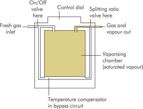
Variable bypass vaporiser
In this vaporiser the fresh gas flow to the patient circuit is split into two streams by a flow-splitting valve. One stream bypasses the vaporising chamber and is free from volatile agent. The other stream passes through the chamber and becomes saturated with vapour. This second stream then rejoins the bypass flow to give the required concentration of vapour in the fresh gas flow to the patient (Figure 46.12). The final vapour concentration is controlled by using the flow-splitting valve to vary the fraction of the gas flow passing through the vaporising chamber. Accuracy is therefore dependent on the flow-splitting valve maintaining a constant flow-splitting ratio over the range of flow rates used. There are two main types of variable bypass vaporiser, described below: plenum vaporisers and draw-over vaporisers.
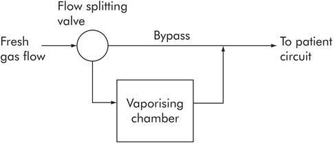
Principles of a variable bypass vaporiser
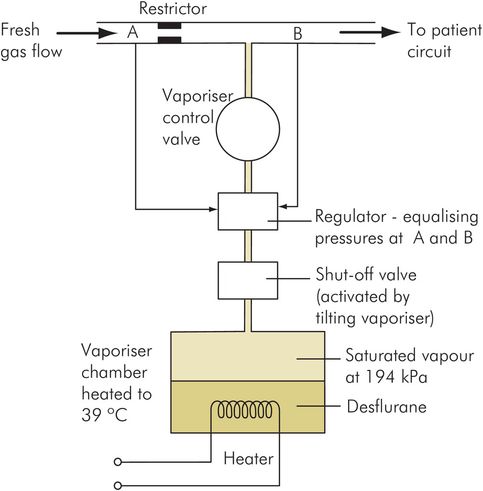
Measured flow vaporiser
This vaporiser has a chamber in which the volatile agent is heated by an electrical element to produce pure vapour under pressure. The pressure produced in the chamber is equal to the SVP of the volatile agent at the preset temperature. The vaporiser then controls the addition of the pressurised vapour to the fresh gas flow using a pressure sensor-controlled valve, to maintain a given volatile percentage in the patient’s inspired gases. This type of device is used for desflurane (Figure 46.13).
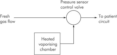
Principles of measured flow vaporiser
Plenum variable bypass vaporisers
Examples – Blease Datum, Drager Vapor, Ohmeda TEC 5
In the plenum vaporiser the inspired gases are at higher than atmospheric pressure by 1–8 kPa, and pressurise the vaporiser chamber. Pressurisation increases the density of the carrier gas in the chamber, thus ensuring better mixing with the vapour at low flows.
When the vaporiser chamber is at atmospheric pressure, carrier gas density is less than vapour density, and at low flow rates gas will tend to pass across the top of the chamber without mixing.
The plenum vaporiser is the most commonly used type in hospital practice. Plenum vaporisers have a relatively high flow resistance (approximately 0.4 kPa per litre per minute of flow) and are therefore unsuitable for placing ‘in line’ in a spontaneously breathing circuit.
In order to develop a peak inspiratory flow rate of 30 litres per minute through this vaporiser, a patient would need to develop a peak inspiratory pressure of 30 × 0.4 = 12 kPa (> 120 cmH2O), compared with a normal inspiratory pressure of < 2 kPa. Effectively the plenum vaporiser acts as a flow restrictor, and for a spontaneously breathing patient a circuit with a reservoir bag is needed to supply the peak inspiratory flow rates. Figure 46.14 illustrates the design of a simple plenum vaporiser.
Flow-splitting ratio
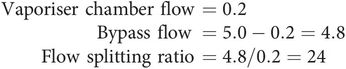
The performance of variable bypass vaporisers depends on the flow-splitting ratio, which is the ratio of the bypass flow to the gas flow through the chamber.
If total gas flow through the anaesthetic machine back bar is 5 litres per minute, and flow through the vaporiser is 0.2 litres per minute, what is the flow-splitting ratio?
Draw-over variable bypass vaporisers
Examples – Epstein, Goldman, Macintosh, Oxford (EMO), Oxford Miniature
In the draw-over vaporiser the inspiratory gases are at atmospheric pressure and are drawn through the vaporiser chamber by the inspiratory efforts of the patient. The vaporiser and flow-splitting valve must therefore have low resistance. This type of vaporiser has the advantage that atmospheric air can be used as the carrier gas (supplemented by cylinder oxygen if required).
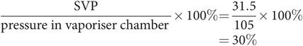
First find the concentration of vapour in an isoflurane vaporiser chamber at 20 °C (SVP for isoflurane at 20 °C = 31.5 kPa; assume ambient pressure in the vaporiser chamber to be 105 kPa).
Saturated vapour concentration in the vaporiser chamber is given by the ratio
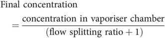
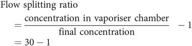
Therefore a flow-splitting ratio of 29 is required, i.e. 1/30 (3.3%) of the total flow must pass through the chamber.
The more potent the volatile agent, the greater the dilution of the vapour required, and the greater the flow-splitting ratio.
However, accuracy is poor in this type of vaporiser since flow rates vary considerably through the vaporiser with the respiratory cycle. The ability of the flow-splitting valve to maintain a constant splitting ratio becomes poor over the wide range of flows. At low flow rates the resistance of the flow-splitting valve will become relatively more significant and gases will tend to bypass the vaporiser, causing a fall in volatile concentrations. At high flow rates there will be increased dilution of the vapour in the vaporiser chamber, and again concentrations will tend to be reduced. Figure 46.15 shows a simple draw-over vaporiser.
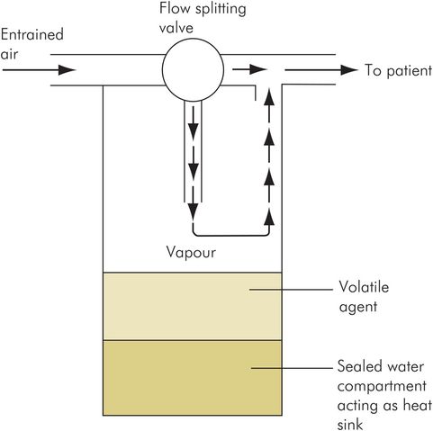
Draw-over vaporiser
Measured flow vaporisers
Example – Ohmeda TEC 6 Desflurane vaporiser
The measured flow vaporisers produce a separate independent flow of vapour or saturated carrier gas. This flow is then metered into the patient’s fresh gas flow to produce the required concentration of volatile agent (Figure 46.16). Thus no splitting of the fresh gas flow occurs.
Measured flow vaporiser
This is because the boiling point of desflurane at sea level is 23.6 °C, which is close to room temperature. In such a case, use of a plenum vaporiser with an intermittently boiling volatile agent would make its performance unpredictable. The desflurane vaporiser therefore heats the volatile agent to 39 °C to produce a chamber pressure of approximately 194 kPa. A continuous flow of desflurane vapour from the chamber is then added to the fresh gas flow via the concentration control valve.
Features of a desflurane vaporiser include:
Mains supply, with backup battery
Three built-in heaters to boil the desflurane and to prevent condensation in different parts of the vaporiser
A warm-up time of 10 minutes, during which the control dial is locked
Electronic circuitry to indicate ‘ready for use’, to warn of low levels of desflurane or disconnection, and to switch off when tilted
Vaporiser performance
Vaporiser performance is dependent on the range of flow rates, the ambient conditions and the carrier gas mixture used, together with the design and maintenance of the vaporiser.
Flow rate
Flow rate of carrier gas passing through the vaporiser is important because as flow rate increases, an increasing amount of vapour is required to saturate the carrier gas. At higher flow rates the carrier gas in the vaporiser chamber may not become fully saturated, and thus the concentration of the volatile agent delivered to the patient tends to fall. Figure 46.17 shows how volatile agent concentration might vary with increasing flow rate in a plenum vaporiser. In addition, high flow rates will accentuate the temperature effects in the chamber (see below). Performance of a vaporiser will therefore be more consistent if variations in flow rates are minimised. A large surface area for vaporisation in the vaporiser chamber will be able to maintain saturation of the carrier gas over a wider range of flow rates.
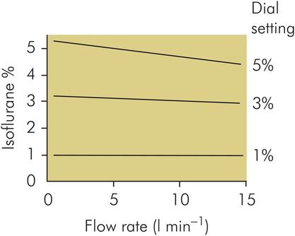
Concentration changes with flow in a plenum vaporiser
Temperature
The concentration of vapour in the vaporiser chamber is dependent on the SVP of the volatile agent and the ambient pressure in the chamber. Temperature affects the performance of a vaporiser due to the variation of SVP with temperature. A main cause of temperature falling in the chamber is the absorption of latent heat as vaporisation occurs. This will become more marked at higher flow rates, when the rate of vaporisation is increased.
Compensation to correct for such fluctuations is achieved by adjusting the gas flow through the vaporiser chamber. Temperature compensation was performed manually in early vaporisers by altering the flow-splitting valve according to the temperature in the vaporiser, or by using a simple automatic device, such as a bimetallic-strip-controlled flow valve. However, modern plenum vaporisers may incorporate electronically controlled flow valves, which are also integrated into the machine by a microprocessor. However, the basic principle of increasing the flow through the vaporiser chamber if the temperature in the chamber starts to fall remains the same.
Further compensation is obtained by increasing the thermal capacity of the vaporiser in order to smooth out temperature fluctuations. This was achieved in the EMO draw-over vaporiser by filling a compartment in the base of the vaporiser with water. Alternatively, in the later plenum vaporisers, a large heavy mass of copper is incorporated into the vaporiser body. This enhanced thermal capacity acts as a heat source in case of temperature falls, and a heat sink should ambient temperature rise, thus smoothing out the effects of temperature fluctuations. Figure 46.18 shows how vaporiser performance might vary with temperature in a typical modern vaporiser.
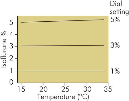
Concentration changes with temperature in a plenum vaporiser (TEC 4) at 5 L min–1 oxygen flow
Related posts:


Stay updated, free articles. Join our Telegram channel

Full access? Get Clinical Tree


