The most important (but often overlooked) item in the pre-use checkout of the anesthesia workstation is to have immediately available, a functioning self-inflating resuscitation bag and a full auxiliary tank of oxygen.
 The low-pressure circuit (LPC) is the “vulnerable area” of the anesthesia workstation because it is most subject to breakage and leaks. The LPC is located downstream from all anesthesia machine safety features except the oxygen analyzer (or, in some cases, the ratio controller), and it is the portion of the machine where a leak is most likely to go unrecognized if an inappropriate LPC leak test is performed. Leaks in the LPC can cause delivery of a hypoxic or sub-anesthetic mixture, leading to patient hypoxic injury or awareness during anesthesia.
 Because some GE Healthcare/Datex-Ohmeda anesthesia machines have a one-way check valve in the low-pressure circuit (LPC), a negative-pressure leak test is required to detect leaks in the LPC. A positive-pressure leak test will not detect leaks in the LPC of a machine with an outlet check valve.
 Internal vaporizer leaks can only be detected with the vaporizer turned to the “on” position. In the “off” position the vaporizer is excluded from the low-pressure circuit.
 Before administering an anesthetic, the circle breathing system must be checked for leaks and for correct flow. To test for leaks, the circle system is pressurized to 30 cm water pressure, and the circle system airway pressure gauge is observed (static test). To check for appropriate flow to rule out obstructions and faulty valves, the ventilator and a test lung (breathing bag) are used (dynamic test). In addition, the manual/bag circuit must be actuated by compressing the reservoir bag, in order to rule out obstructions to flow in the manual/bag mode.
 Many new anesthesia workstation self-tests do not detect internal vaporizer leaks unless each vaporizer is individually turned on during repeated self-tests.
 In the event of a gas pipeline crossover, two actions must be taken. The backup oxygen cylinder must be turned on (since the tank valve should always be turned off when not in use), and the wall/pipeline supply sources must be disconnected.
 The oxygen failure cutoff valves (also known previously as “fail-safe” valves, “hypoxic guards,” or “proportioning systems”) help minimize the likelihood of delivery of a hypoxic gas mixture, but they are not foolproof. Delivery of a hypoxic mixture may still result from (1) the wrong supply gas, either in the cylinder or in the main pipeline; (2) a defective or broken safety device; (3) leaks downstream from the safety devices; (4) inert gas administration (for instance, helium may not be subject to the oxygen failure cutoff valve); and (5) dilution of the inspired oxygen concentration by high concentrations of inhaled anesthetics.
 Because of desflurane’s low boiling point (22.8°C) and high vapor pressure (669 mm Hg at 20°C), controlled vaporization of desflurane requires specially designed vaporizers, such as the GE Healthcare/Datex-Ohmeda Tec 6, the Dräger D-Vapor, and the GE Healthcare Aladin cassette vaporizing system.
 Misfilling an empty variable bypass vaporizer with desflurane could theoretically be catastrophic, resulting in delivery of a hypoxic mixture and a massive overdose of inhaled desflurane anesthetic.
 Inhaled anesthetics can interact with CO2 absorbents and produce toxic compounds. During sevoflurane (only) anesthesia, compound A can be formed, particularly at low fresh gas flow rates. During desflurane>sevoflurane anesthesia, carbon monoxide can be produced, particularly with desiccated absorbents.
 Desiccated strong base absorbents (particularly barium hydroxide lime, Baralyme) can react with sevoflurane, producing extremely high absorber temperatures and combustible decomposition products. These in combination with the oxygen- or nitrous oxide-enriched environment of the circle system have produced very high temperatures and fires within the breathing system. For this reason, Baralyme is no longer available in the United States.
 Anesthesia ventilators with ascending bellows (bellows that ascend during the expiratory phase) were initially thought to be safer than descending bellows. This is because a breathing system disconnection would be obvious since the ascending bellows would not refill/rise during exhalation. Contemporary machines with descending bellows, however, have been carefully redesigned to address these initial limitations. Current descending bellows ventilators have featherlight bellows, an electric eye at the bottom of the bellows housing to detect bellows movement, and the bellows housing is subjected to PEEP, such that in case of a disconnect, the bellows would actually rise and stay up.
 With older design machines, use of the oxygen flush valve during the inspiratory phase of mechanical ventilation could cause barotrauma, particularly in pediatric patients. The newer workstations have fresh-gas decouplers or peak-inspiratory pressure limiters that were designed to prevent these complications. Ventilators that use fresh gas decoupling technology virtually eliminate the possibility of barotrauma by oxygen flushing during the inspiratory phase because fresh gas flow and oxygen flush flow are diverted to the reservoir bag. However, if the reservoir bag has a large leak or is absent altogether, patient awareness under anesthesia and delivery of a lower-than-expected oxygen concentration could occur because of entrainment of room air.
 With newer GE Healthcare/Datex-Ohmeda anesthesia ventilators such as the 7900 series SmartVent, both the patient circuit gas and the drive gas are scavenged, resulting in substantially increased volumes of scavenged gas. Thus, the scavenging system flow removal must be set appropriately high to accommodate the increased volume; otherwise, undesired PEEP and contamination of the operating room environment could result.
 Modern ventilators compensate for the changes in fresh gas flow, respiratory rate, and I:E ratio so that the delivered tidal volume does not change from that set to be delivered. This compensation is achieved either by “fresh gas decoupling” (in Dräger Fabius, Tiro, and Apollo workstations) or by “fresh gas compensation” (in GE Healthcare/Datex-Ohmeda workstations).
Multimedia
 Bourdon Tube
 Circle System
 Liquid Oxygen Storage Tank
 E-Cylinder
 Oxygen Proportioning Systems
 Oxygen Flush Valve
 Vaporizer Interlocking Mechanism
 Desflurane
 CO2 Absorber
 Rebreathing CO2
 Ventilator Bellows
 Ascending Bellows Ventilator
 Wire Anenometers
 Scavenger System
INTRODUCTION
The anesthesia machine is, conceptually, a pump for delivering medical gases and inhalation agents to the patient’s lungs. The function of the anesthesia machine is to (1) receive gases from the central supply and cylinders, (2) meter them and add anesthetic vapors, and finally, (3) deliver them to the patient breathing circuit.1 This machine has evolved over the past 160 years from a rather simple ether inhaler to a complex device of valves, pistons, vaporizers, monitors, and electronic circuitry.
The “pump” in the modern anesthesia machine is either a mechanical ventilator or the lungs of the spontaneously breathing patient, or perhaps, a combination of the two. The anesthesia pump has a supply system: medical gases from either a pipeline supply or a gas cylinder, alongside vaporizers delivering potent inhaled anesthetic agents that are mixed with the medical gases. The anesthesia pump also has an exhaust system, the waste gas scavenging system, which removes excess gases from the patient’s breathing circuit. The breathing circuit is a series of hoses, valves, filters, switches, and regulators that interconnect the supply system, the patient, and the exhaust system.
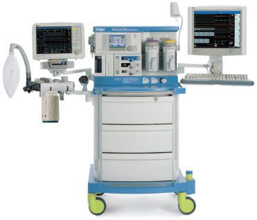
Modern anesthesia machines (Figs. 24-1 and 24-2) are now more properly referred to as anesthesia workstations. The anesthesia workstation, as defined by the ASTM International (ASTM, originally known as the American Society for Testing and Materials), is a system for administering anesthetics to patients consisting of the anesthesia gas supply device, the anesthesia ventilator, monitoring devices, and protection devices.2 The protection device is designed to prevent the patient from hazardous output due to incorrect delivery of energy or substances; for example, the adjustable pressure-limiting (APL) valve prevents barotrauma.
FIGURE 24-2. GE Healthcare Aisys Anesthesia Carestation. This workstation has electronic control of gas flows using a gas mixer and an electronically controlled Aladin vaporizing system for potent inhaled volatile anesthetics. (Courtesy GE Healthcare.)
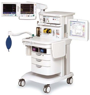
FIGURE 24-1. Dräger Medical Fabius GS anesthesia workstation. (Courtesy Dräger Medical AG.)
In this chapter, the anesthesia workstation is examined piece by piece. The normal operation, function, and integration of major anesthesia workstation subsystems are described. More importantly, the potential problems and hazards associated with the various components of the anesthesia delivery system, and the appropriate preoperative checks that may help to detect and prevent such problems, are illustrated.
ANESTHESIA WORKSTATION STANDARDS AND PRE-USE PROCEDURES
A few years ago, a fundamental knowledge of the basic anesthesia machine pneumatics would have sufficed for most anesthesia providers. Today, a detailed understanding of pneumatics, electronics, and even computer science is necessary to fully understand the capabilities and complexities of the anesthesia workstation. Along with the changes in the composition of the anesthesia workstation to include more complex ventilation systems and integrated monitoring, recently there has also been increasing divergence between anesthesia workstation designs from different manufacturers. In 1993, a joint effort between the American Society of Anesthesiologists (ASA) and the U.S. Food and Drug Administration (FDA) produced the 1993 FDA Anesthesia Apparatus Pre-Use Checkout Recommendations (Appendix A). This pre-use checklist was versatile and could be applied to most commonly available anesthesia machines equally well and did not require users to vary the pre-use procedure significantly from machine to machine.
Today, because of variations in fundamental anesthesia workstation design, the 1993 FDA pre-use checklist is no longer applicable to many contemporary workstations. Anesthesia providers must be aware of this limitation, and the original equipment manufacturer’s recommended pre-use checklist should be followed. Some of the newer workstations have computer-assisted self-tests that automatically perform a part of the pre-use machine checkout procedure. The availability of such automated checkout features further adds to the complexity of constructing a uniform pre-use checklist such as the one utilized in the recent past. Ultimately, the responsibility of performing an adequate pre-use checkout of the anesthesia workstation falls to the individual operator: regardless of the level of his/her training and the quality of technical support. The anesthesia care provider has the ultimate responsibility for proper function of all anesthesia delivery equipment that he or she uses. The anesthesia provider of record must be aware of which anesthesia workstation components are checked out by the automated self-tests and which ones are not. Because of the number of workstations currently available and the variability among their self-testing procedures, the following discussion will be limited to general topics related to these systems.
STANDARDS FOR ANESTHESIA MACHINES AND WORKSTATIONS
The American National Standards Institute (ANSI) and the American Society for Testing and Materials (ASTM) define standards for anesthesia machines and workstations, and provide guidelines to manufacturers regarding their minimum performance, design characteristics, and safety requirements. Newly manufactured workstations must have monitors that measure the following parameters: continuous breathing system pressure, exhaled tidal volume, ventilatory CO2 concentration, anesthetic vapor concentration, inspired oxygen concentration, oxygen supply pressure, arterial hemoglobin oxygen saturation, arterial blood pressure, and continuous electrocardiogram. The anesthesia workstation must have a prioritized alarm system that groups the alarms into three categories: high, medium, and low priority. These monitors and alarms may be enabled automatically and made to function by turning on the anesthesia workstation, or the monitors and alarms can be enabled manually and made functional by following a pre-use checklist.2,3
Perhaps just as important as the specifications for new anesthesia machines and workstations that are introduced into clinical care are the characteristics that render older machines obsolete. This is not an inconsequential issue, since the financial investment for replacing older machines is significant. The ASA document, “Guidelines for Determining Anesthesia Machine Obsolescence,” addresses some of the absolute as well as relative criteria that can help institutions make a decision on when even otherwise functioning equipment should be replaced.4
FAILURE OF ANESTHESIA EQUIPMENT
An 11-year study of 1,000 anesthesia incidents in the United Kingdom revealed that the most common failure was due to an equipment leak (61/1,000).5 The authors stated the most likely underlying cause of system leaks was due to “design weakness”; for example, push-on tapers in breathing circuits that can easily become disconnected. Poor equipment maintenance and setup were the second most common underlying causes of equipment failure. Equipment failure due to entrapped cables may result in the inability to ventilate (thus warranting careful attention to organization and tidiness of the anesthesia workstation environment by the anesthesia provider).6–8 The authors found that the pulse oximeter alarm was the most common, principal monitor alerting the anesthesiologist to an equipment problem.
In a review of the ASA “Closed Claims” database, Caplan et al. found that although claims related to the medical gas-delivery system were rare, when they occurred, they were usually severe, 76% resulting in death or permanent brain injury. The most common malfunction in Caplan et al’s review was the breathing circuit (39%), followed by vaporizers (21%), ventilators (17%), gas tanks or gas lines (11%), and the anesthesia machine itself (7%). Use error was judged to be the cause in 75% of the 72 gas delivery equipment claims reviewed, while pure failure of equipment was considered the cause in the remainder.9
SAFETY FEATURES OF NEWER ANESTHESIA WORKSTATIONS
Older conventional anesthesia machines have design limitations that limit their safety. For example, some machines may lack features to prevent barotrauma during oxygen flush, lack automated pre-use checkout, have multiple external connections, and have gas-driven ventilator bellows that do not fully empty and which may allow “breath stacking” as well as inaccurate tidal volume delivery.10
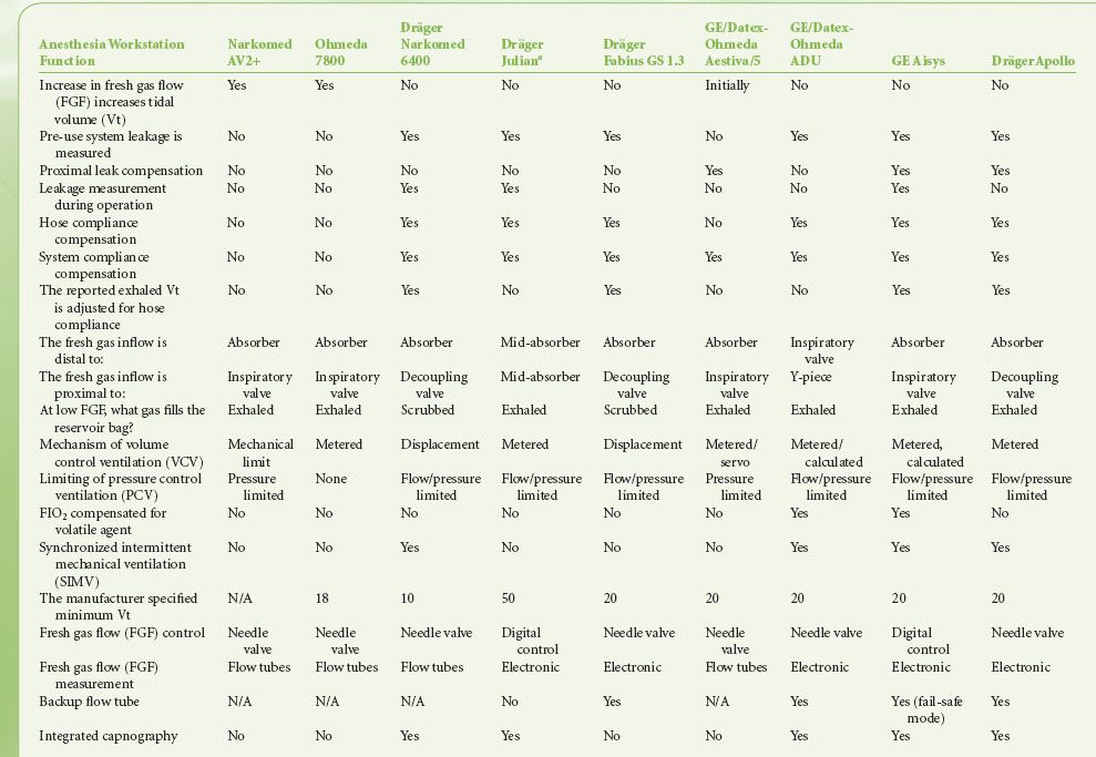
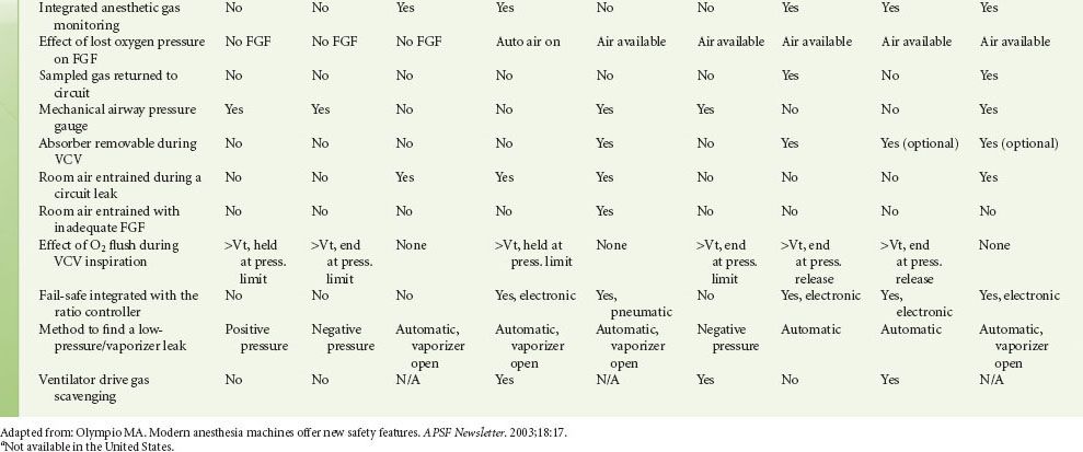
Modern workstations have designs that incorporate additional safety features such as fresh gas decoupling to prevent barotrauma during oxygen flush, have integrated, software-driven self-checkout routines, have limited external connections, and have electronic, piston-driven ventilators that deliver accurate tidal volumes.10 Table 24-1 summarizes relevant safety features of newer anesthesia workstations.
TABLE 24-1. COMPARISON OF ANESTHESIA WORKSTATION FUNCTIONS
CHECKOUT OF THE ANESTHESIA WORKSTATION
A complete anesthesia apparatus checkout procedure must be performed each day prior to the first use of the anesthesia workstation. An abbreviated checkout procedure should be performed before each subsequent case. The 1993 FDA Anesthesia Apparatus Checkout Recommendations (reproduced in Appendix A) remain applicable to the majority of older anesthesia machines in use worldwide.11–15
In 2008 the ASA published recommendations for pre-anesthesia checkout machines, taking into consideration newer workstations that perform automated checkout.16 Since the design of newer workstations varies considerably, no single pre-use procedure is applicable. These guidelines present a template for individual departments and practitioners to design pre-anesthesia checkout procedures specific to their needs and equipment (Appendix B). Sample checkout procedures are published on the ASA website (http://www.asahq.org), and they encompass adult as well as pediatric equipment from major equipment manufacturers in the United States. The reader is strongly encouraged to review the checkout procedures reproduced in Appendices A and B and to understand the rationale for and importance of each step. 
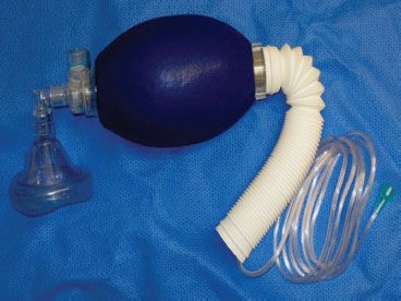
Perhaps the most important but often overlooked item in the pre-use checkout of the anesthesia workstation is to have immediately available a functioning (tested) self-inflating resuscitation  bag (SIRB) and a full auxiliary tank of oxygen (Fig. 24-3). This is “plan B”—the backup plan. Many of the adverse outcomes associated with anesthesia equipment mishaps could have been averted if the SIRB had been used or used sooner. A recent study reported that the SIRB was the item most frequently missed in the pre-anesthesia setup.17
FIGURE 24-3. Self-inflating resuscitation bag (SIRB). Many of the adverse outcomes associated with anesthesia equipment mishaps could have been averted if a functional SIRB had been used sooner.
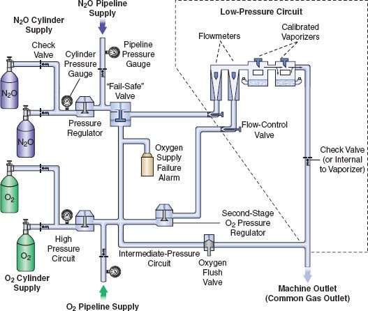
The next three most important preoperative checks are (1) oxygen analyzer calibration, (2) the low-pressure circuit leak test, and (3) the circle system test. These are discussed in the following sections. Additional details regarding these systems are presented briefly in subsequent sections describing the anatomy of the anesthesia workstation; for a more comprehensive review, the reader is encouraged to consult the operator’s manual of their own equipment manufacturer. For a simplified diagram of a two-gas anesthesia machine and the components described in the following discussion, please refer to Figure 24-4. A comprehensive discussion of Figure 24-4 can also be found in the Anesthesia Workstation Pneumatics section.
FIGURE 24-4. Diagram of a generic two-gas anesthesia machine. (Modified with permission from: Check-Out, A Guide for Preoperative Inspection of an Anesthesia Machine. Park Ridge, IL: American Society of Anesthesiologists; 1987.)
Oxygen Analyzer Calibration
The oxygen analyzer is one of the most important monitors on the anesthesia workstation. It is the only machine safety device that evaluates the integrity of the low-pressure circuit in an ongoing fashion. Other machine safety devices, such as the oxygen failure cutoff (“fail-safe”) valve, the oxygen supply failure alarm, and the proportioning system, are all upstream from the flow control valves. The only machine monitor that detects problems downstream from the flow control valves is the oxygen analyzer. Calibration of this monitor is described in Appendix A (Anesthesia Apparatus Checkout Recommendations, 1993, Step 9). The actual procedure for calibrating the oxygen analyzer has remained reasonably similar over the recent generations of the anesthesia workstations (Guideline for Designing Pre-Anesthesia Checkout Procedures, 2008, Item 10 in Appendix B). Generally, the oxygen concentration-sensing element (usually a fuel cell on traditional machines) must be exposed to room air (at sea level) for calibration to 21%. This may require manually setting a dial on older machines, but on newer ones, it usually only involves temporary removal of the sensor, selecting and then confirming that the oxygen calibration is to be performed from a set of menus on the workstation’s display screen, and finally reinstalling the sensor. The function of the low oxygen concentration alarm should be verified by setting the alarm to trigger above the current oxygen reading. Newer workstations have automatic oxygen sensor calibration.
Low-Pressure Circuit Leak Test
The low-pressure circuit leak test checks the integrity of the anesthesia machine from the flow control valves to the common gas outlet.  It evaluates the portion of the machine that is downstream from all safety devices except the oxygen analyzer. The components located within this area are precisely the ones most subject to breakage and leaks. Leaks in the low-pressure circuit can cause hypoxia or patient awareness.18,19 Flow tubes, the most delicate pneumatic component of the machine, can crack or break. A typical three-gas anesthesia machine has 16 O-rings in the low-pressure circuit. Leaks can occur at the interface between the glass flow tubes.20 and the manifold, and at the O-ring junctions between the vaporizer and its manifold. Loose filler caps on vaporizers are a common source of leaks, and these leaks can lead to delivery of sub-anesthetic doses of inhaled agents, causing patient awareness during general anesthesia.18,21
Several different methods have been used to check the low-pressure circuit for leaks. They include the oxygen flush test, the common gas outlet occlusion test, the traditional positive-pressure leak test, the North American Dräger positive-pressure leak test, the Ohmeda 8000 internal positive-pressure leak test, the Ohmeda negative-pressure leak test, the 1993 FDA universal negative-pressure leak test, and others. One reason for the large number of methods is that the internal design of various machines differs considerably. The most notable example is that many GE Healthcare/Datex-Ohmeda (hereafter referred to as Datex-Ohmeda) machines/workstations have a check valve near the common gas outlet, whereas Dräger Medical workstations do not. The presence or absence of the outlet check valve profoundly influences which pre-use check is indicated.
Several mishaps have resulted from application of the wrong leak  test to the wrong machine.22–25 Therefore, it is mandatory to perform the appropriate low-pressure leak test each day. To do this, it is essential to understand the exact location and operating principles of the Datex-Ohmeda check valve. Many Datex-Ohmeda anesthesia workstations have a machine outlet check valve located in the low-pressure circuit (Table 24-1). The check valve is located downstream from the vaporizers and upstream from the oxygen flush valve (Fig. 24-4). It is open in the absence of back pressure. Gas flow from the manifold moves the rubber flapper valve off its seat and allows gas to proceed freely to the common gas outlet. The valve closes when back pressure is exerted.12,26 Back pressure sufficient to close the check valve may occur with the following conditions: oxygen flushing, peak breathing circuit pressures generated during positive-pressure ventilation, or use of a positive-pressure leak test.
Generally speaking, the low-pressure circuit of anesthesia workstations without an outlet check valve can be tested using a positive-pressure leak test, and machines with outlet check valves must be tested using a negative-pressure leak test. When performing a positive-pressure leak test, the operator generates positive pressure in the low-pressure circuit using flow from the anesthesia machine or from a positive-pressure squeeze bulb to detect a leak. When performing a negative-pressure leak test, the operator creates negative pressure in the low-pressure circuit using a suction bulb to detect leaks. Two different low-pressure circuit leak tests are described below.
Oxygen Flush Positive-Pressure Leak Test
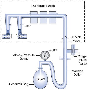
Historically, older anesthesia machines did not have check valves in the low-pressure circuit. Therefore, it was common practice to pressurize the breathing circuit and the low-pressure circuit with the oxygen flush valve to test for internal anesthesia machine leaks by observing the breathing system pressure gauge. Because many  modern Datex-Ohmeda machines now have check valves in the low-pressure circuit, application of a positive-pressure leak test to these machines can be misleading or even dangerous (Fig. 24-5). Inappropriate use of the oxygen flush valve or the presence of a leaking flush valve may lead to inadequate evaluation of the low-pressure circuit for leaks. In turn, this can lead the workstation user into a false sense of security despite the presence of large leaks.22–24,27,28 Positive pressure from the breathing circuit results in closure of the outlet check valve, and the value on the breathing system pressure gauge will fail to decrease. The system appears to be gas tight, but in actuality, only the circuitry downstream from the outlet check valve is leak-free.29 Thus, a vulnerable area exists from the check valve back to the flow control valves because this area is not tested by a positive-pressure leak test.
FIGURE 24-5. Inappropriate use of the oxygen flush valve to check the low-pressure circuit of an Ohmeda machine equipped with a check valve. The area within the rectangle is not checked by the inappropriate use of the oxygen flush valve. The components located within this area are precisely the ones most subject to breakage and leaks. Positive pressure within the patient circuit closes the check valve, and the value on the airway pressure gauge does not decrease despite leaks in the low-pressure circuit.
Verifying the Integrity of the Gas Supply Lines between the Flowmeters and the Common Gas Outlet
The 1993 FDA Universal negative-pressure leak test (Appendix A, Step 5) was named “universal” because at that time it could be used to check all contemporary anesthesia machines regardless of the presence or absence of an outlet check valve in the low-pressure circuit.13 It remains applicable for many older anesthesia machines, but for many newer machines this “universal” test is not applicable. Table 24-1 describes how newer workstations are tested for low-pressure circuit and vaporizer leaks. Leaks in the gas supply lines between the flowmeters and the common gas outlet should be checked daily or whenever a vaporizer is changed (Appendix B, Item 8). The most thorough technique is to check each vaporizer individually by turning it on and then evaluating the low-pressure system for leaks. It is important to note that automated checkout procedures may not necessarily evaluate leaks at the vaporizer, if the vaporizer is not turned on during testing. In addition, vaporizers should be adequately filled and filler ports should be tightly closed (Appendix B, Item 7). As mentioned previously, the ASA now recommends that individual institutions develop internal guidelines specific to their own equipment and needs.
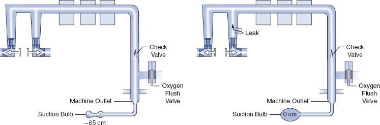
The 1993 FDA low-pressure system leak check is based on the Datex-Ohmeda negative-pressure leak test (Fig. 24-6). It is performed using a negative-pressure leak testing device, which is a simple suction 15 cc volume bulb that when evacuated generates a negative pressure of 65 mm Hg. The machine main ON/OFF switch, the flow control valves, and the vaporizers are all turned off. The suction bulb is connected to the common gas outlet and squeezed repeatedly until it is fully collapsed. This action creates a vacuum in the low-pressure system circuitry. The machine is considered leak-free if the suction bulb remains collapsed for at least 10 seconds. A leak is present if the bulb reinflates during this period. The test is repeated with each vaporizer individually turned to the on position because internal vaporizer leaks can be detected only when the vaporizer is turned on and becomes part of the low-pressure system. If the bulb reinflates in less than 10 seconds, a leak is present somewhere in the low-pressure circuit.

FIGURE 24-6. FDA negative-pressure leak test. (Left) A negative-pressure leak testing device is attached directly to the machine common gas outlet. Squeezing the bulb creates a vacuum in the low-pressure circuit and opens the check valve. (Right) When a leak is present in the low-pressure circuit, room air is entrained through the leak and the suction bulb inflates. (Reprinted with permission from: Andrews JJ. Understanding anesthesia machines. In: 1988 Review Course Lectures, p 78. Cleveland: International Anesthesia Research Society, 1988.)
Evaluation of the Circle System
The circle system tests (Appendix B, Items 12–13) evaluate the integrity of the circle breathing system, which spans from the machine common gas outlet to the Y-piece (Fig. 24-7). The test has two components: (1) breathing system pressure and leak testing and (2) verification that gas flows properly through the breathing circuit during both inspiration and exhalation. To thoroughly check the circle system for leaks, valve integrity, and obstruction, both tests must be performed preoperatively. The ASA 2008 recommendations call for performing the breathing system test and leak test before starting each case, such that pressure can be developed in the system during both manual/bag and automatic/mechanical ventilation. Automated leak testing routines are implemented in modern workstations; system compliance is also calculated and used to adjust volume delivery during mechanical ventilation (Appendix B, Item 12). Because pressure and leak testing cannot identify all obstructions in the breathing circuit or confirm the function of the inspiratory and expiratory unidirectional valves, a test lung or second reservoir bag connected at the Y-piece can be used to confirm circuit integrity and function. Visual inspection of the unidirectional valves should be performed daily, though, because subtle damage to these valves is difficult to determine. Older 1993 FDA checkout procedures to identify valve incompetence that may not be visually obvious can be implemented, but are typically too complex for daily testing (Appendix B, Item 13).30,31
FIGURE 24-7. Components of the circle breathing system. B, reservoir bag; V, ventilator; APL, adjustable pressure-limiting (pop-off) valve. (Reproduced with permission from: Brockwell RC. Inhaled anesthetic delivery systems. In: Miller RD, ed. Anesthesia. 6th ed. Philadelphia, PA: Churchill Livingstone; 2004:295.)
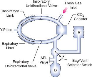
In the 1993 FDA Anesthesia Apparatus Checkout Recommendations, a leak test is performed by closing the APL (or pop-off) valve, occluding the Y-piece, and pressurizing the circuit to 30 cm water pressure using the oxygen flush valve. The value on the pressure gauge will not decrease if the circle system is leak-free, but this does not assure unidirectional valve integrity or function. The value on the pressure gauge will read 30 cm H2O even if the unidirectional valves are stuck shut or are incompetent. In addition, a flow test checks the integrity of the unidirectional valves, and it detects obstruction in the circle system. It can be performed by removing the Y-piece from the circle system and breathing through the two corrugated hoses individually. The unidirectional valve leaflets should be present and should move appropriately. The operator should be able to inhale but not be able to exhale through the inspiratory limb. The operator should be able to exhale but not inhale through the expiratory limb. The flow test can also be performed by using the ventilator and a reservoir bag connected to the “Y” piece as described in the 1993 FDA Anesthesia Apparatus Checkout Recommendations (Appendix A, Steps 11–12).13
Workstation Self-Tests
Many new anesthesia workstations now incorporate technology that allows the machine to either automatically or manually guide the user through a series of self-tests to check for functionality of electronic, mechanical, and pneumatic components. Tested components commonly include the gas supply system, flow control valves, the circle system, ventilator, and integrated vaporizers. The comprehensiveness of these self-diagnostic tests varies from one model and manufacturer to another. If these tests are to be employed, users must be certain to read and strictly follow all manufacturer recommendations. Although a thorough understanding of what the particular workstation’s self-tests include is very helpful, this information is often difficult to obtain and may vary greatly between devices.
One  particularly important point of caution with self- tests should be noted on systems with manifold-mounted vaporizers such as the Dräger Apollo, Dräger Fabius GS and Narkomed 6000 series. A manifold-mounted vaporizer does not become a part of an anesthesia workstation’s low-pressure system until its concentration control dial is turned to the “on” position. Therefore, to detect internal vaporizer leaks in this type of a system, the “leak test” portion of the self-diagnostic must be repeated with each individual vaporizer turned to the “on” position. If this precaution is not taken, large leaks that could potentially result in patient awareness, such as those from a loose filler cap or cracked fill indicator, could go undetected.
Anesthesia Workstation Pneumatics
The Anatomy of an Anesthesia Workstation
A simplified diagram of a generic two-gas anesthesia machine is shown in Figure 24-4. The pressures within the anesthesia workstation can be divided into three circuits: a high-pressure, an intermediate-pressure, and a low-pressure circuit. The high-pressure circuit is confined to the cylinders and the cylinder primary pressure regulators. For oxygen, the pressure range of the high-pressure circuit extends from a high of 2,200 pounds per square inch gauge (psig) to 45 psig, which is the regulated cylinder pressure. For nitrous oxide in the high-pressure circuit, pressures range from a high of 750 psig in the cylinder to a low of 45 psig. The intermediate-pressure circuit begins at the regulated cylinder supply sources at a pressure of 45 psig, includes the pipeline sources at 50 to 55 psig and extends to the flow control valves. Depending on the manufacturer and specific machine design, second-stage pressure regulators may be used to decrease the pipeline supply pressures to the flow control valves to even lower pressures such as 14 psig or 26 psig within the intermediate-pressure circuit.32,33 Finally, the low-pressure circuit extends from the flow control valves to the common gas outlet. Therefore, the low-pressure circuit includes the flow tubes, vaporizer manifold, vaporizers, and the one-way outlet check valve on most GE Healthcare/Datex-Ohmeda machines.33
Both oxygen and nitrous oxide are supplied to the workstation from two sources: a pipeline supply source and a cylinder supply source. The pipeline supply source is the primary gas source for the anesthesia workstation. The hospital pipeline supply system provides gases to the machine at approximately 50 psig, which is the normal working pressure of most machines  . The cylinder supply source serves as a backup if the pipeline supply fails or acts as the primary supply if the anesthesia workstation is being used in a location without the availability of pipeline supplied gases. As previously described, the oxygen cylinder source is regulated from 2,200 psig to approximately 45 psig, and the nitrous oxide cylinder source is regulated from 745 psig to approximately 45 psig.32–34
A safety device traditionally referred to as the fail-safe valve (and currently more appropriately termed the “oxygen failure cutoff valve”) is located downstream from the nitrous oxide supply source. It serves as an interface between the oxygen and nitrous oxide supply sources. This valve shuts off, or proportionally decreases, the supply of nitrous oxide (and other gases) if the oxygen supply pressure decreases. To meet ASTM standards, contemporary machines have an alarm device to monitor the oxygen supply pressure. A high-priority alarm is actuated when a decreasing oxygen supply pressure reaches a predetermined threshold, such as 30 psig.32–34
Many GE Healthcare/Datex-Ohmeda machines have a second-stage pressure regulator for oxygen that is located downstream from the oxygen supply source in the intermediate-pressure circuit. It is adjusted to a precise pressure level, such as 14 psig.32 This regulator supplies a constant pressure to the oxygen flow-control valve regardless of fluctuating oxygen pipeline pressures. The flow from the oxygen flow-control valve will be constant provided that its oxygen supply pressure is >14 psig.
The flow control valves represent an important anatomic landmark within the anesthesia workstation because they separate the intermediate-pressure circuit from the low-pressure circuit. The low-pressure circuit is that part of the machine that lies downstream from the flow control valves. The operator regulates flow entering the low-pressure circuit by adjusting the flow control valves. The oxygen and nitrous oxide flow-control valves are linked mechanically or pneumatically by a proportioning system to help prevent unintended delivery of a hypoxic mixture. After leaving the flow tubes, the mixture of gases travels through a common manifold and may be directed to a concentration-calibrated vaporizer. Precise amounts of potent inhaled volatile anesthetic can be added, depending on vaporizer concentration control dial setting. The total fresh gas flow (FGF) plus the anesthetic vapor then flow toward the common gas outlet.32,33
Many Datex-Ohmeda anesthesia machines have a one-way check valve located between the vaporizers and the common gas outlet in the mixed-gas line. Its purpose is to prevent back flow into the vaporizer during positive-pressure ventilation, therefore minimizing the effects of downstream intermittent pressure fluctuations on inhaled anesthetic concentration (see Vaporizers: Intermittent Back Pressure section). The presence or absence of this check valve profoundly influences which preoperative leak test is indicated (see Checking Your Anesthesia Workstation). The oxygen flush connection joins the mixed-gas line between the one-way check valve (when present) and the machine common gas outlet. Thus, when the oxygen flush valve is activated the pipeline oxygen flows directly to the common gas outlet at a rate of 35 to 75 L/min and potentially at a pressure of 55 psig.
Pipeline Supply Source
Most hospitals today have a central piping system to deliver medical gases including oxygen, nitrous oxide, air, and carbon dioxide to outlets in the operating room. The central piping system must supply the correct gases at the appropriate pressure for the anesthesia workstation to function properly. Unfortunately, this does not always occur. Even as recently as 2002, a large medical center with a huge cryogenic bulk oxygen storage system was not immune to component failures that contributed to a critical oxygen pipeline supply failure.35 In this case, a faulty joint ruptured at the bottom of the primary cryogenic oxygen storage tank, releasing 8,000 gallons of liquid oxygen to flood the streets in the surrounding area and compromised oxygen delivery to the medical center.
In a 1976 survey of approximately 200 hospitals, 31% reported difficulties with pipeline systems.36 The most common problem was inadequate oxygen pressure, followed by excessive pipeline pressures. The most devastating reported hazard, however, was accidental crossing of oxygen and nitrous oxide pipelines, which has led to many deaths. This problem caused 23 deaths in a newly constructed wing of a general hospital in Sudbury, Ontario, during a 5-month period.37 In 2002, two hypoxic deaths were reported in New Haven, Connecticut. These resulted from a medical gas system failure in which an altered oxygen flowmeter was connected to a wall supply source for nitrous oxide.38
In the event that a pipeline crossover is suspected, the workstation user  must immediately take two corrective actions. First, the backup oxygen cylinder should be turned on. Then, the pipeline supply must be disconnected. This second step is mandatory because the machine will preferentially use the (potentially) inappropriate 50 psig pipeline supply source instead of the lower-pressure (45 psig) oxygen cylinder source if the wall supply is not disconnected. Recent publications suggest that many anesthesia providers may not appreciate the importance of or reasons for these actions.39,40
The wall outlet connections for pipeline gases are gas-specific. If they are “quick connect” fittings then they are gas-specific within the same manufacturer. For example, a wall oxygen outlet made by Ohmeda will not accept an oxygen connector made by Chemetron, even though the gas is the same. This can create problems if outlets and connectors by more than one manufacturer exist in the same facility.41 Many institutions seeking to create uniformity are now using nationally standardized Diameter Index Safety System (DISS) threaded connections. The DISS provides threaded, noninterchangeable connections for medical gas lines, which minimizes the risk of misconnection. Regardless of which type of gas-specific connector (DISS or “quick connect”) exists at the wall end of the hose conducting gas to the anesthesia machine, the gas enters the anesthesia machine through DISS inlet connections (see Fig. 24-4; arrows). A pressure gauge measures the pipeline gas pressure when the machine is connected to a pipeline supply. A check valve is located downstream from the inlet. It prevents reverse flow of gases from the machine to the pipeline or the atmosphere.
Cylinder Supply Source
Anesthesia workstations have E-cylinders for use when a pipeline supply source is not available or if the pipeline system fails. Anesthesia providers can easily become complacent and falsely assume that backup gas cylinders are, in fact, present on the anesthesia workstation, and further, if present, that they contain an adequate supply of compressed gas. The pre-use checklist should contain steps that confirm both.
Medical gases supplied in E-cylinders are attached to the anesthesia machine via the hanger yoke assembly. The hanger yoke assembly orients and supports the cylinder, provides a gas-tight seal, and ensures a unidirectional flow of gases into the machine.33 Each hanger yoke is equipped with the Pin Index Safety System (PISS). The PISS is a safeguard introduced to eliminate cylinder interchanging and the possibility of accidentally placing the incorrect gas on a yoke designed to accommodate another gas. Two metal pins on the yoke assembly are arranged so that that they project into corresponding holes in the cylinder valve. Each gas or combination of gases has a specific and unique pin arrangement.42,43 A failure of the pin index system, and medical staff to properly identify E-cylinder contents, was the cause of an intraoperative fire during laparoscopy.44 A mixture of oxygen and CO2 was utilized rather than 100% CO2.
Once the cylinders are turned on, compressed gases may pass from their respective high-pressure cylinder sources into the anesthesia machine (see Fig. 24-4). A check valve is located downstream from each cylinder if a double-yoke assembly is used. This check valve serves several functions. First, it minimizes gas transfer from a cylinder at high pressure to one with a lower pressure. Second, it allows an empty cylinder to be exchanged for a full one while gas flow continues from the other cylinder into the machine with minimal loss of gas or supply pressure. Third, it minimizes leakage from an open cylinder to the atmosphere if one cylinder is absent.32,33 A cylinder supply pressure gauge is located downstream from the check valves. The gauge will indicate the pressure in the cylinder having the higher pressure when two reserve cylinders of the same gas are opened at the same time.
Each cylinder supply source has a pressure-reducing valve known as the cylinder pressure regulator. It reduces the high and variable storage pressure present in a cylinder to a lower, more constant pressure suitable for use in the anesthesia machine. The oxygen cylinder pressure regulator reduces the oxygen cylinder pressure from a high of 2,200 psig to approximately 45 psig. The nitrous oxide cylinder pressure regulator receives pressure of up to 745 psig and reduces it to approximately 45 psig.32,33
The gas supply cylinder valves should be turned off when not in use, except during the preoperative machine pre-use checkout. If the cylinder supply valves are left open, the reserve cylinder supply can be silently depleted whenever the pressure inside the machine decreases to a value lower than the regulated cylinder pressure. For example, oxygen pressure within the machine can decrease below 45 psig with oxygen flushing or possibly even during the use of a pneumatically driven ventilator, particularly at high inspiratory flow rates. In addition, the pipeline supply pressures of all gases can fall to less than 45 psig if problems exist in the central piping system. If the cylinders are left open when this occurs, they will eventually become depleted and no reserve supply may be available if a complete central pipeline failure were to occur.29,32
The amount of time that an anesthesia machine can operate from the E-cylinder supply is important knowledge. This is particularly true now that anesthesia is being provided more frequently in office-based and in remote (outside the OR) hospital settings where pipeline oxygen may not be available. Oxygen can exist only in gaseous form at room temperature, and it obeys Boyle’s law which states that for a fixed mass of gas at constant temperature, the product of pressure times volume is constant.45 The volume of oxygen available from the cylinder is directly proportional to the cylinder pressure.
 An E-cylinder has an internal volume of 4.8 L and when “full” is pressurized to 2,000 psig. Since psig is the pressure measured in excess of atmospheric pressure (14.7 psia, pounds per square inch absolute pressure), the cylinder pressure is 2,014.7 psia. Applying Boyle’s Law:

Therefore, V2, the volume of oxygen in a “full” E-cylinder at 1 atm is

The following equation has been proposed to help estimate the remaining time that oxygen can be delivered at a given flow rate46:
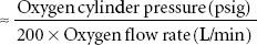
For example, an E-cylinder of oxygen with a pressure of 1,000 psig, used at an oxygen flow rate of 5 L/min would be depleted in
[1,000/(200 × 5)]  1 hour
It should be noted that this calculation will provide only a gross estimate of remaining time and may not be exact. Furthermore, users should be cautioned that use of a pneumatically driven mechanical ventilator will dramatically increase oxygen utilization rates and decrease the remaining time until the cylinder is depleted. Uses of spontaneous or manual ventilation, with low FGF rates in a circle system with CO2 absorption, will significantly reduce oxygen consumption from an E-cylinder if this is the only source of oxygen available.7,8,35 Because electrically powered piston type anesthesia ventilators, such as found in the Dräger Fabius GS and Apollo workstations, do not impact oxygen usage rates they may be preferable to conventional gas-driven ventilators in practice settings where the supply of compressed gas cylinders may be limited.
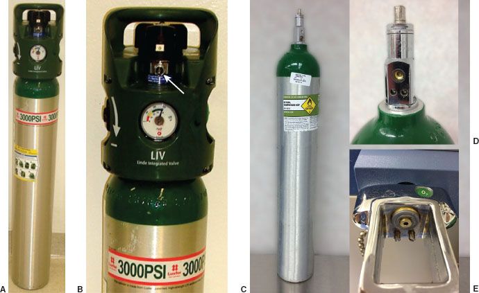
A new regulator for E-cylinders of oxygen is available that permits controlled delivery of oxygen via a nozzle at flows of ≤25 L/min for patient transport (Fig. 24-8 A,B,C,D and E). The tank regulator also permits delivery of oxygen at 50 psig from a DISS connection (Fig. 26-9). If the oxygen hose from the anesthesia machine is connected to a central source (e.g., at the wall) via a DISS connector, and that central source becomes unavailable, then the machine hose can be easily connected to the tank’s DISS connector and provide a backup supply of oxygen (Fig. 24-9 B). A conventional E cylinder with pin index safety system is shown in Fig. 24-8, C,D,E.
FIGURE 24-8. (A) 3,000 psig E-cylinder with Linde Integrated Valve LIV (B), Linde Gas North America LLC that permits adjustable flows of ¼ to 25 L/min from the low-pressure nozzle (B-arrow). There is also a high-pressure regulator that can supply oxygen at 50 psig via a DISS connector. Standard E-cylinder (C) showing pin-index safety system (D) and mating yoke (E).
Related posts:


Stay updated, free articles. Join our Telegram channel

Full access? Get Clinical Tree


