CHAPTER 39
Vertebral Augmentation
INTRODUCTION
The aging population gives us cause for great concern especially in those suffering from osteoporosis. Rates are climbing, especially in women. Osteoporosis has reached epidemic proportions and is a major public health issue for an estimated 44 million Americans and 200 million people world wide. According to the 2005 annual report of The National Osteoporosis Foundation, 1 in every 2 women and 1 in every 4 men aged 50 and older suffered from osteoporosis-related fracture. Vertebral compression fractures (VCFs) constitute the most frequent complication of osteoporosis, with nearly half of all of the 2 million bone fractures caused by osteoporosis. The estimated medical cost in 2005 was over $16.9 billion. The prevalence of VCFs increases with age, reaching 40% in women over 80 years of age. Women with clinically diagnosed VCFs have a 15% higher mortality rate and are 2 to 3 times more likely to die of pulmonary causes. Over 50% of people with 1 or 2 VCFs, require self-care assistance, which is significantly higher compared to 8% of osteoarthritis patients suffering from low back pain. It is noteworthy that each VCF increases the chance of another VCF by 19.2% within the same year. Two VCFs increase the probability of a third fracture by 24% within a year.
• The severe pain caused by VCFs is exacerbated by movement and weight-bearing activity and is linked to significant morbidities and impaired quality of life, the majority of which is caused by pain and immobility, which can lead to:
![]() Chronic pain which is often accompanied by depression and/or anxiety.
Chronic pain which is often accompanied by depression and/or anxiety.
![]() Reduced FVC by 9% leading to an increased risk of atelectasis and pneumonia.
Reduced FVC by 9% leading to an increased risk of atelectasis and pneumonia.
![]() Worsening of osteoporosis. Bone mineral density is reduced at a rate of 2% per week.
Worsening of osteoporosis. Bone mineral density is reduced at a rate of 2% per week.
![]() 1% to 3% muscle wasting per day.
1% to 3% muscle wasting per day.
![]() Decubitus ulcers.
Decubitus ulcers.
![]() Higher risk of developing deep vein thrombosis and subsequent pulmonary embolism, which may be fatal.
Higher risk of developing deep vein thrombosis and subsequent pulmonary embolism, which may be fatal.
• Opioid medications that are prescribed for the treatment of pain can often cause loss of appetite, nausea, constipation, changes in mental status, ie, confusion and are associated with an increased risk of dependence and addiction.
• The morbidity and mortality associated with osteoporotic vertebral fractures demand the need for more aggressive treatment. Vertebral augmentation techniques have been used as a viable treatment option providing the possibility for rapid pain relief and improved mobility. Percutaneous vertebroplasty has been considered a developing standard of care for VCFs.
• Vertebral compression fractures may also be secondary to tumor infiltration. The most frequent malignant lesions of the spine include osteolytic metastasis and myeloma. Current cancer therapy prolongs life expectancy, although the increasing risk for these patients to develop metastatic vertebral involvement and collapse persists.
• Galliber, Deramond, and colleagues performed the first case of percutaneous vertebroplasty in France in 1984. It was not until 1993 that Jensen and colleagues at the University of Virginia performed the first vertebroplasty in the United States.
• Vertebroplasty has gained widespread popularity, mostly because of significantly high rates of success, low incidence of complications or adverse events, brief surgical time and recovery period, limited sedation, and short to no hospital stay.
• Kyphoplasty was introduced in 2000, as the first vertebral augmentation technique, with proposed advantage of restoring fracture height and reducing kyphosis.
• Vertebroplasty involves the use of acrylic bone cement to stabilize and treat painful VCFs.
• Vertebral augmentation techniques (ie, kyphoplasty) initially create a cavity in the vertebral body and then the cavity is filled with bone cement material. In the case of kyphoplasty, cavity creation is facilitated by an inflatable bone tamp.
• The mechanism by which cement injection attenuates pain remains unclear. Theories include thermal necrosis, chemotoxicity of the interosseous pain receptors, mechanical stabilization, and neurotoxicity mediated by the cement monomer.9,10
• The main goal of treatment should be pain relief and resumption of mobility.
![]() This is contrary to “conventional conservative treatment,” which prescribes bed rest and the administration of pain medications, usually from the opioid family of prescription drugs.
This is contrary to “conventional conservative treatment,” which prescribes bed rest and the administration of pain medications, usually from the opioid family of prescription drugs.
![]() In an effort to reduce the risk of leakage from liquid bone cement, multiple new products including high viscosity cement and Cortoss have been introduced. The main advantages are higher viscosity resulting in less liquidity, lower exothermic temperatures that will not cause tissue necrosis, no monomer release, stiffness, and mechanical strength that is similar to bone and, lower adjacent level fracture.
In an effort to reduce the risk of leakage from liquid bone cement, multiple new products including high viscosity cement and Cortoss have been introduced. The main advantages are higher viscosity resulting in less liquidity, lower exothermic temperatures that will not cause tissue necrosis, no monomer release, stiffness, and mechanical strength that is similar to bone and, lower adjacent level fracture.
INDICATIONS
• Vertebral augmentation and vertebroplasty are indicated for the treatment of painful vertebral compression fractures (VCFs) that are acute or subacute (as evidenced by T2-weighted MRI) resulting from osteoporosis, trauma, and tumor infiltration.
![]() Preferably the facture should have less than 50% height loss.
Preferably the facture should have less than 50% height loss.
![]() Measurement of the height and comparative calculations should be made with a radiograph performed in supine position during inspiration because weight bearing and exhalation may exaggerate bone collapse.
Measurement of the height and comparative calculations should be made with a radiograph performed in supine position during inspiration because weight bearing and exhalation may exaggerate bone collapse.
RELEVANT ANATOMY
• VCFs typically occur at the anterior third of the vertebral body where trabecular bone is less prominent.
![]() VCFs alter the biomechanics of the spine, making adjacent vertebral bodies more vulnerable to fracture.
VCFs alter the biomechanics of the spine, making adjacent vertebral bodies more vulnerable to fracture.
![]() It should be noted that above the level of T8, the relationship between the vertebral body and the pedicle is different than the rest of the thoracic spine. The pedicles are almost perpendicular to the vertebral body and if a practitioner tries to reach the vertebral body through the pedicle in an oblique view, they will probably end up directly in the spinal canal. Hence, a parapedicular approach is recommended above T8 level.
It should be noted that above the level of T8, the relationship between the vertebral body and the pedicle is different than the rest of the thoracic spine. The pedicles are almost perpendicular to the vertebral body and if a practitioner tries to reach the vertebral body through the pedicle in an oblique view, they will probably end up directly in the spinal canal. Hence, a parapedicular approach is recommended above T8 level.
BASIC CONCERNS AND CONTRAINDICATIONS
• Osteoporotic VCFs are associated with significant morbidities and impaired quality of life, the majority of which is caused by pain and immobility.
Standard contraindications are as follows:
![]() Presence of pain with radicular symptoms that do not correspond to the area of the fracture
Presence of pain with radicular symptoms that do not correspond to the area of the fracture
![]() More than 20% retropulsion of vertebral body fragment as evidenced by computed axial tomography (CT) or MRI
More than 20% retropulsion of vertebral body fragment as evidenced by computed axial tomography (CT) or MRI
![]() Active localized or systemic infection
Active localized or systemic infection
![]() Known allergy to PMMA (polymethylmethacrylate)
Known allergy to PMMA (polymethylmethacrylate)
![]() Uncorrected coagulopathy
Uncorrected coagulopathy
![]() Painless compression fracture
Painless compression fracture
![]() Complete vertebral collapse
Complete vertebral collapse
![]() Epidural tumor
Epidural tumor
![]() Patient unable or unwilling to give informed consent
Patient unable or unwilling to give informed consent
PREOPERATIVE CONSIDERATIONS
• The main indication for the procedure is painful compression fracture. In other words, pain needs to be consistent with imaging findings.
![]() In order to establish the correct diagnosis clinically one may also perform examination under fluoroscopy, which is also equally important for assessing the feasibility of safe needle placement and performing a successful procedure (Figure 39-1).
In order to establish the correct diagnosis clinically one may also perform examination under fluoroscopy, which is also equally important for assessing the feasibility of safe needle placement and performing a successful procedure (Figure 39-1).
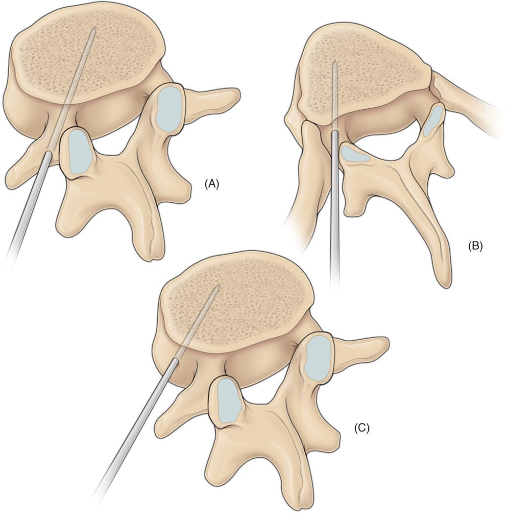
Figure 39-1. A diagrammatic sketch showing the commonly used routes of spinal needle entry into the vertebral body during the percutaneous vertebroplasty procedure. Due to the broad-based pedicles, (A) a transpedicular approach is often used in the lumbar territory. (B) The costopedicular or (C) paravertebral approaches are usually employed in the thoracic region as the pedicles possess a narrow needle entry point. These alternative approaches are also used in situations where there is significant tumor destruction of the pedicles.
![]() If the patient is too osteoporotic and bony landmarks are not clearly identifiable to safely see the pathway for proper needle placement, the procedure should be performed under CT guidance. Utilize CT guidance for factures T6 and above.
If the patient is too osteoporotic and bony landmarks are not clearly identifiable to safely see the pathway for proper needle placement, the procedure should be performed under CT guidance. Utilize CT guidance for factures T6 and above.
![]() For additional safety, injection of cement needs to be performed under real-time imaging. Usually this is not feasible with standard CT scanners; therefore, we advocate use of fluoroscopy in conjunction with CT scan (Figure 39-2A, B).
For additional safety, injection of cement needs to be performed under real-time imaging. Usually this is not feasible with standard CT scanners; therefore, we advocate use of fluoroscopy in conjunction with CT scan (Figure 39-2A, B).
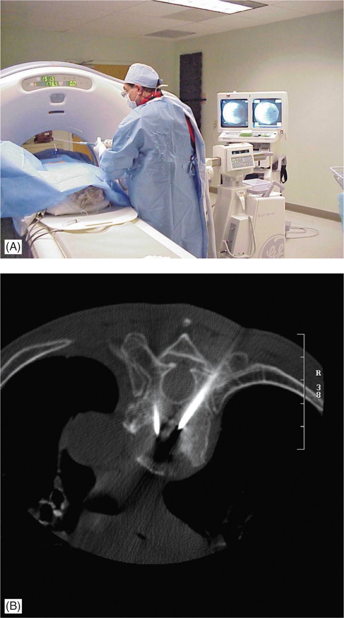
Figure 39-2. (A, B) C-arm fluoroscopy is placed in lateral view to monitor real-time imaging 1B while injecting bone cement, following placement of needles under CT-guidance.
IMAGING
• X-rays are usually the first step in radiologic diagnosis of vertebral compression fractures, but the age and extent of VCF can be confirmed with MRI.
![]() STIR images and T2-weighted fat suppression images have the highest diagnostic value.
STIR images and T2-weighted fat suppression images have the highest diagnostic value.
![]() In case of contraindication for MRI (ie, pacemakers, spinal cord stimulators, etc) a CT or bone scan may provide relevant information. A CT scan will also be valuable in diagnosing the presence and severity of retropulsed bone fragments and, mapping the needle approach for the procedure.
In case of contraindication for MRI (ie, pacemakers, spinal cord stimulators, etc) a CT or bone scan may provide relevant information. A CT scan will also be valuable in diagnosing the presence and severity of retropulsed bone fragments and, mapping the needle approach for the procedure.
![]() Although not considered an absolute contraindication, the presence of retropulsion will require extra vigilance to avoid acute spinal canal stenosis caused by further retropulsion of the fragment dorsally and or leakage of cement (Figure 39-3A-C).
Although not considered an absolute contraindication, the presence of retropulsion will require extra vigilance to avoid acute spinal canal stenosis caused by further retropulsion of the fragment dorsally and or leakage of cement (Figure 39-3A-C).
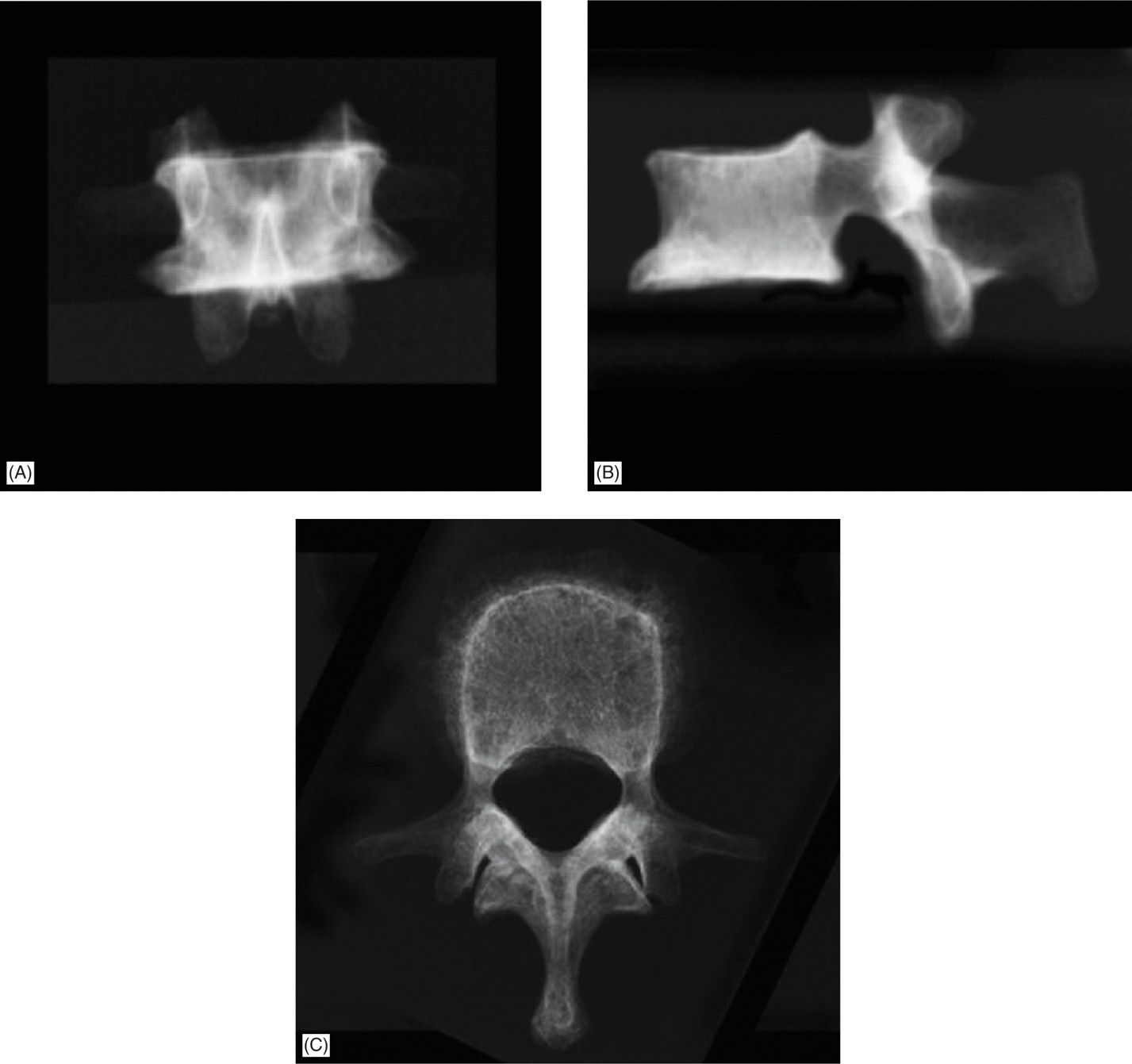
Figure 39-3. (A, B) Two-dimensional fluoroscopy in AP and lateral view. (C) Ideal view is an axial view that could be obtained with CT scan.
TECHNIQUE
• Vertebroplasty involves the use of acrylic bone cement to stabilize and treat painful vertebral compression fractures.
• Vertebral augmentation (ie, kyphoplasty) utilizes a bone tamp: an inflatable balloon inserted into the vertebral body and inflated to create a cavity for the bone cement.
• Both procedures are performed under sterile conditions, local anesthesia and IV sedation or monitored anesthesia care (MAC).
![]() Prophylactic antibiotics like cefazolin 1 g IV (or clindamycin 600 mg IV in case of allergy) are administered 30 minutes prior to skin penetration.
Prophylactic antibiotics like cefazolin 1 g IV (or clindamycin 600 mg IV in case of allergy) are administered 30 minutes prior to skin penetration.
![]() Appropriate padding during positioning is essential to avoid new osteoporotic fractures in areas like the ribs. If possible, it is advocated to ask the patients to position themselves to avoid any unrecognized pressure points.
Appropriate padding during positioning is essential to avoid new osteoporotic fractures in areas like the ribs. If possible, it is advocated to ask the patients to position themselves to avoid any unrecognized pressure points.
• Most of the time, a minimal dose of IV anesthetic is used at the time of local anesthetic injection for skin and subcutaneous tissue. This allows for a continuous and meaningful interaction with the patient during the procedure. If the periosteum is well anesthetized, the patient will tolerate the procedure and further sedation is not needed.
• Vertebroplasty is most commonly performed by using a transpedicular approach but due to anatomical differences above T8 level, a parapedicular approach is advocated.
![]() The target point for needle is the junction of anterior and middle third of the vertebral body.
The target point for needle is the junction of anterior and middle third of the vertebral body.
![]() There still remains controversy over the advantage of using unipedicular (one needle) versus bipedicular approach and some recommend the bipedicular approach for the novice practitioners.
There still remains controversy over the advantage of using unipedicular (one needle) versus bipedicular approach and some recommend the bipedicular approach for the novice practitioners.
TRANSPEDICULAR VERSUS PARAPEDICULAR APPROACH
• Following site preparation and sterile draping, the fluoroscope is rotated to the oblique view until the pedicles of the VBFs are in a “Scottie dog” view (Figure 39-4). Then, the C-arm is tilted (rostral-caudal rotation) until the pedicle (the eye of the Scottie dog) (Figure 39-5) is in the upper half of the vertebral body.
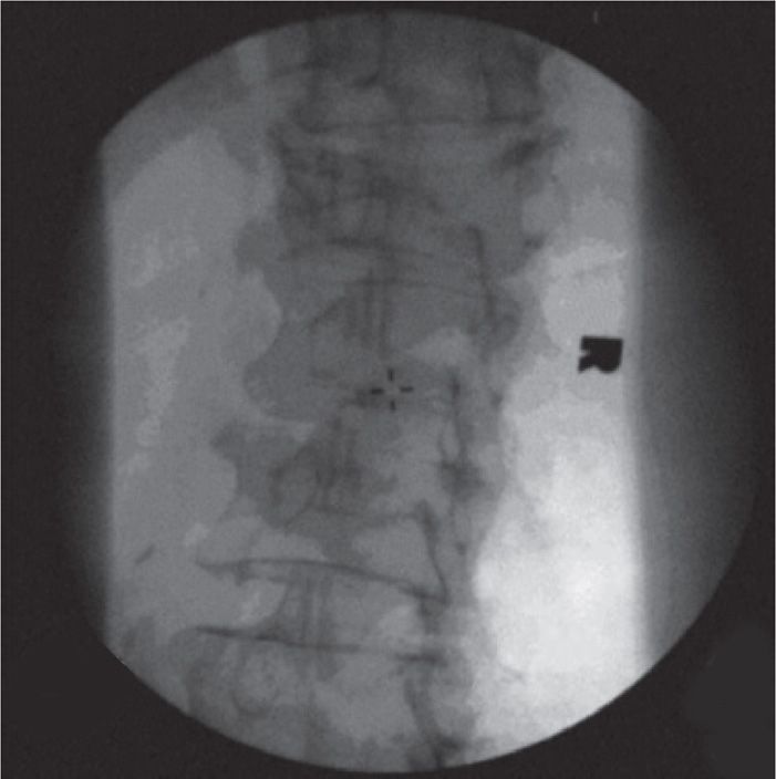
Figure 39-4. Initial “Scottie dog” view of vertebral body.
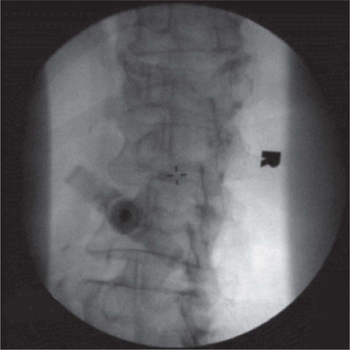
Figure 39-5. Oblique view of the vertebroplasty needle in the pedicle.
• Skin and subcutaneous tissues are anesthetized with lidocaine 1% to 2%, using a 25-guage, 1.5-in needle, which can reach the periosteum most of the time. If it does not, the direction of the needle needs to be reevaluated.
• Multidirectional fluoroscopic guidance may help to expedite the procedure if it is available. One C-arm is placed in lateral position, while the other is switched between anterior-posterior (AP) and oblique views.
• Under fluoroscopic guidance at the level of the pedicle (oblique view), an 11-gauge vertebroplasty needle for the lumbar vertebrae, or a 13-gauge needle for thoracic vertebrae, is inserted in the tunnel view directed to the “eye” of the Scottie dog, which will be the upper outer half of the face of the pedicle (Figure 39-6).
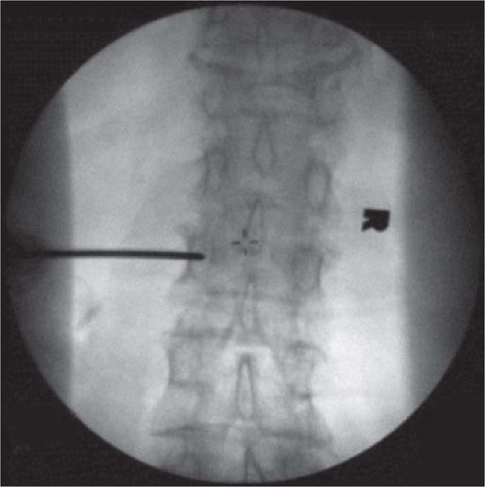
Figure 39-6. AP view of the vertebroplasty needle in the pedicle.
• Once the needle is stable in the pedicle (Figure 39-7) the C-arm is rotated to lateral view to make sure that the needle follows the axis of the pedicle (Figure 39-8A-D). If one follows proper angulations, the tip of the needle will reach the target point at the junction of the anterior and middle third of the vertebral body.
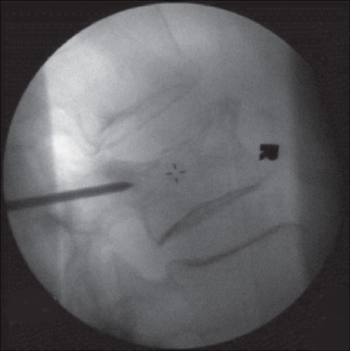
Figure 39-7. Lateral view of the vertebroplasty needle in the pedicle.
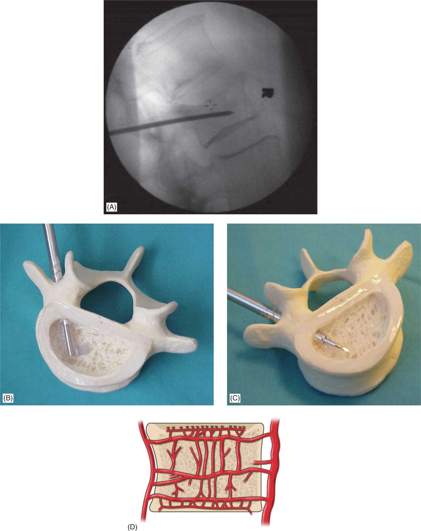
Figure 39-8. (A) Lateral view of the vertebroplasty needle in the final position. (B, C) Final needle placement using transpedicular approach. (D) Basivertebral venous complex. Note the intricate latticework of the vertebral vasculature; this venous complex must be avoided when injecting cement.
![]() It is advantageous to have a good view of the intervertebral foramen and to confirm that the needle is angled away from it.
It is advantageous to have a good view of the intervertebral foramen and to confirm that the needle is angled away from it.
• Advancement of the needle is best achieved by holding and stabilizing the needle with one hand and using a mallet with the other. This will ensure safe and controlled advancement of the needle. Then, gradually advance the needle through the pedicle into the vertebral body.
• To avoid the risk of spinal injury, it is imperative to avoid the needle violating the medial border of the pedicle (in AP view), while the needle is in the pedicle (in lateral view). Once the pedicle has been passed, the C-arm should be placed in lateral view and the needle slowly advanced until it reaches the junction of the anterior third and the middle third of the vertebral body (Figure 39-8b,c).
![]() There is still controversy over the advantage of using the unipedicular (one needle) versus bipedicular approach (Figures 39-9 and 39-10). In our practice, if the initial needle is located close to the midline, we do not place a second one.
There is still controversy over the advantage of using the unipedicular (one needle) versus bipedicular approach (Figures 39-9 and 39-10). In our practice, if the initial needle is located close to the midline, we do not place a second one.
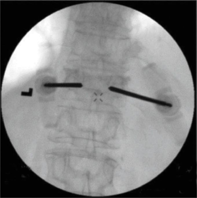
Figure 39-9. AP view of the bipedicular approach.
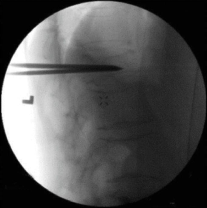
Figure 39-10. Lateral view of the bipedicular approach.
• Once the needle is correctly placed, the cement is prepared according to manufacturer’s recommendations. The cement is allowed to reach the consistency of a thin paste (eg, like that of toothpaste) before deemed suitable for injecting. Then, the stylet is removed from the needle and the cement is slowly injected under continuous (real-time) fluoroscopic imaging (Figures 39-11 and 39-12).
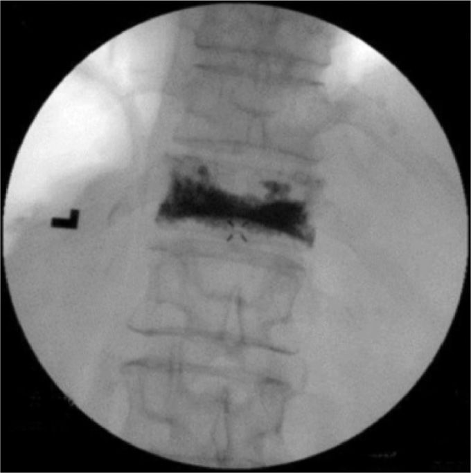
Figure 39-11. Final AP view of vertebroplasty.
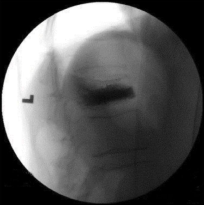
Figure 39-12. Final lateral view of invertebroplasty.
• Safe deposit area (Blue)—target area of cement deposit in anterior two-third of vertebrae
• Danger zone (Red)—posterior area to be avoided (Figure 39-13)
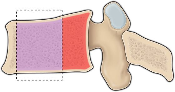
Figure 39-13. Blue area is the area for cement injection, the red area should be avoided.
![]() Total amount to be injected varies according to the area.
Total amount to be injected varies according to the area.
![]() In the lumbar region, a total of 3 to 6 mL is usually enough, while 2 to 3 mL is sufficient in the thoracic area.
In the lumbar region, a total of 3 to 6 mL is usually enough, while 2 to 3 mL is sufficient in the thoracic area.
![]() If there is any sign of cement extrusion or if it moves toward the intervertebral foramen, the injection should immediately stop.
If there is any sign of cement extrusion or if it moves toward the intervertebral foramen, the injection should immediately stop.
![]() If a decision is made to place the second needle on the opposite side, it should be done before mixing the cement.
If a decision is made to place the second needle on the opposite side, it should be done before mixing the cement.
• In our practice, total fluoroscopy time, using pulse mode, may range between 30 and 60 seconds per level treated. The patient may be discharged from recovery once the usual discharge criteria are met.
PARAPEDICULAR APPROACH
• Above the T8 level, the relationship between the vertebral body and the pedicle is different in the thoracic spine. At this level, the pedicle is almost perpendicular to the vertebral body. If one tries to reach the vertebral body through the pedicle in an oblique view (Scottie dog), one will end up directly in the spinal canal. Therefore, a parapedicular approach is recommended above this level.
![]() The lateral aspect of the pedicle is identified and marked with the patient in prone position, and the C-arm in AP view.
The lateral aspect of the pedicle is identified and marked with the patient in prone position, and the C-arm in AP view.
![]() Skin and subcutaneous tissues are anesthetized, using a 25-gauge 3.5-in spinal needle. The advantage of such a long needle is that it will be able to reach the vertebral body and anesthetize the periosteum.
Skin and subcutaneous tissues are anesthetized, using a 25-gauge 3.5-in spinal needle. The advantage of such a long needle is that it will be able to reach the vertebral body and anesthetize the periosteum.
![]() After local anesthesia has been applied; the 13-gauge vertebroplasty needle is inserted, following the trajectory used with the spinal needle. In an AP view, the C-arm is rotated to lateral, and the needle is advanced in a plane parallel to the pedicle, with the needle aiming to the point immediately below the junction of the pedicle and the vertebral body, after the needle has transfixed the skin. Then, the C-arm is continuously rotated between AP and lateral views.
After local anesthesia has been applied; the 13-gauge vertebroplasty needle is inserted, following the trajectory used with the spinal needle. In an AP view, the C-arm is rotated to lateral, and the needle is advanced in a plane parallel to the pedicle, with the needle aiming to the point immediately below the junction of the pedicle and the vertebral body, after the needle has transfixed the skin. Then, the C-arm is continuously rotated between AP and lateral views.
![]() In the AP view, one should make sure that the needle is kept lateral to the middle aspect of the pedicle until bone has been contacted.
In the AP view, one should make sure that the needle is kept lateral to the middle aspect of the pedicle until bone has been contacted.
![]() A mallet may be used to facilitate the vertebroplasty needle’s passing through the periosteum.
A mallet may be used to facilitate the vertebroplasty needle’s passing through the periosteum.
![]() A second needle in the contralateral side is recommended because the needle placement is more difficult with this approach.
A second needle in the contralateral side is recommended because the needle placement is more difficult with this approach.
![]() The steps for cement injection should be followed as with the transpedicular approach, with special attention to cement extrusion.
The steps for cement injection should be followed as with the transpedicular approach, with special attention to cement extrusion.
• The entry point in AP view is lateral and superior to transverse process. Once needle is engaged in bone, need to check in lateral view to confirm correct trajectory (Figure 39-14A-C).
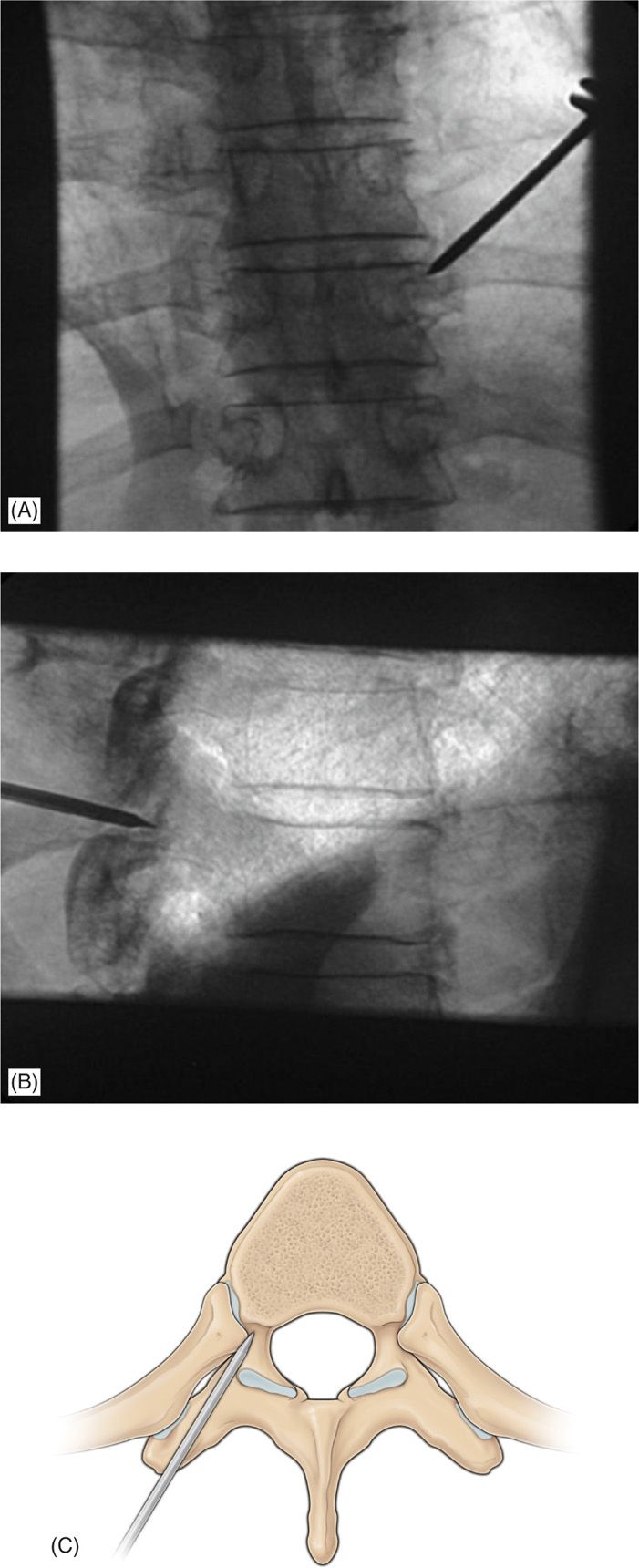
Figure 39-14. (A-C) The entry point in AP view is lateral and superior to transverse process. Once needle is engaged in bone, need to check in lateral view to confirm correct trajectory.
VERTEBRAL AUGMENTATION (IE, KYPHOPLASTY) PROCEDURE
• Kyphoplasty is similar to vertebroplasty in terms of draping, imaging, view, and use of anesthetics.
• The additional steps made for the kyphoplasty procedure are:
![]() The needle is replaced with a cannula and introducer system over a guide pin.
The needle is replaced with a cannula and introducer system over a guide pin.
![]() The introducer fits inside, and extends beyond the cannula.
The introducer fits inside, and extends beyond the cannula.
![]() The beveled tip allows the introducer to be inserted into the vertebral body using a mallet.
The beveled tip allows the introducer to be inserted into the vertebral body using a mallet.
![]() The introducer is then advanced to the posterior aspect of the vertebral body (Figure 39-14A-C).
The introducer is then advanced to the posterior aspect of the vertebral body (Figure 39-14A-C).
![]() Leaving the cannula in place, the introducer is exchanged for a hand-operated drill. The drill is carefully advanced to the anterior aspect of the vertebral body, 3 to 4 mm posterior to the anterior cortical margin (Figure 39-15).
Leaving the cannula in place, the introducer is exchanged for a hand-operated drill. The drill is carefully advanced to the anterior aspect of the vertebral body, 3 to 4 mm posterior to the anterior cortical margin (Figure 39-15).
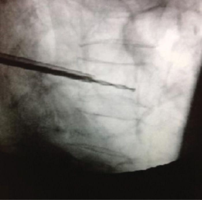
Figure 39-15. Cannula of the kyphoplasty system positioned in posterior third of vertebral body with drill advanced to the anterior third to create a working channel for the introduction of the kyphoplasty balloon.
![]() A near-midline position of the needle tip on the AP view is optimal.
A near-midline position of the needle tip on the AP view is optimal.
![]() The drill is removed and the deflated balloon is inserted into the small cavity (Figure 39-16).
The drill is removed and the deflated balloon is inserted into the small cavity (Figure 39-16).
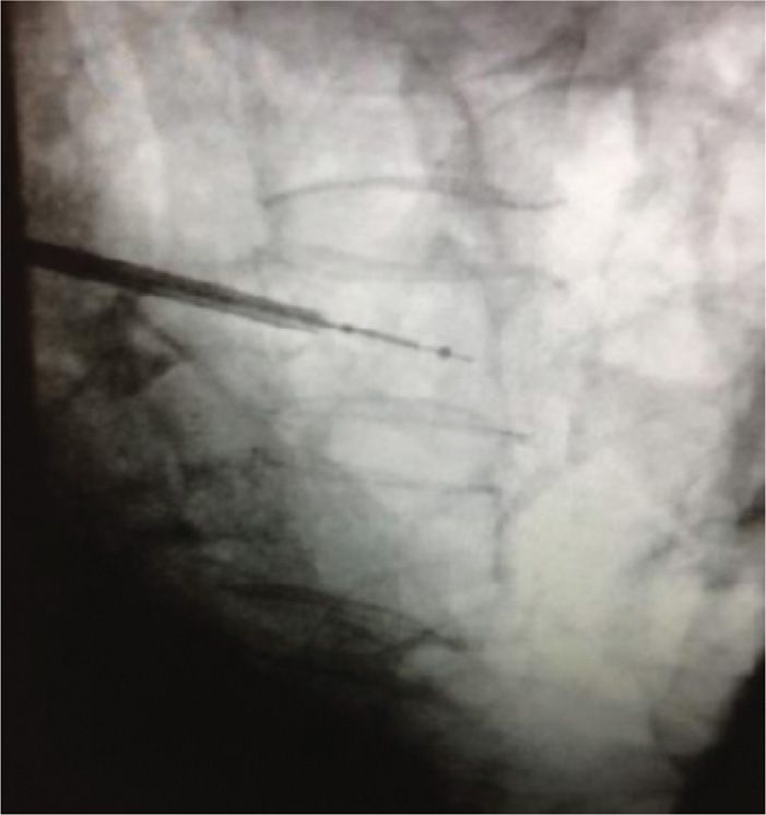
Figure 39-16. Deflated balloon inserted through the cannula and advanced until the proximal mark if visualized out of the cannula. Fluoroscopic guidance helps to determine that the distal aspect of the balloon is in the anterior one-third of the vertebral body.
![]() Then a second introducer is placed from the contralateral side in a similar manner.
Then a second introducer is placed from the contralateral side in a similar manner.
![]() Each balloon is configured with a locking syringe with digital manometer and is slowly inflated with iodinated contrast using pressures of 160 to 400 psi.
Each balloon is configured with a locking syringe with digital manometer and is slowly inflated with iodinated contrast using pressures of 160 to 400 psi.
![]() The inflation is monitored both with the pressure transducer and intermittent fluoroscopy.
The inflation is monitored both with the pressure transducer and intermittent fluoroscopy.
![]() Inflation continues slowly until 1 of the following 3 conditions is met (Figure 39-17):
Inflation continues slowly until 1 of the following 3 conditions is met (Figure 39-17):
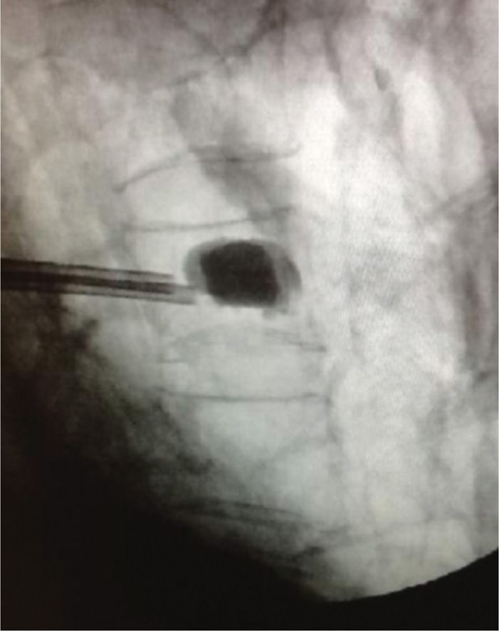
Figure 39-17. Kyphoplasty balloons inflated within the vertebral body.
1. The system reaches maximum pressure or maximum balloon volume.
2. The balloon tamp reaches one of the cortical margins.
3. The kyphotic deformity
is corrected.
![]() The balloon is then deflated and removed.
The balloon is then deflated and removed.
• Cement placement in kyphoplasty
![]() Sufficient time is allowed for the PMMA cement to reach a doughy toothpaste-like consistency.
Sufficient time is allowed for the PMMA cement to reach a doughy toothpaste-like consistency.
![]() The delivery system is connected to the cannula and the cement is slowly injected under real-time fluoroscopic guidance.
The delivery system is connected to the cannula and the cement is slowly injected under real-time fluoroscopic guidance.
![]() The cement fills the cavity from anterior to posterior, matching or slightly exceeding the volume of the cavity created by the inflated balloon.
The cement fills the cavity from anterior to posterior, matching or slightly exceeding the volume of the cavity created by the inflated balloon.
![]() The delivery system is then removed and manual compression is used to achieve hemostasis.
The delivery system is then removed and manual compression is used to achieve hemostasis.
![]() The practitioner should be aware and cautious that poor visualization of osseous structures on fluoroscopy increases the risk of improper needle placement and cement leakage but can be overcome with the use of CT scanner (Figures 39-18 and 39-19).33
The practitioner should be aware and cautious that poor visualization of osseous structures on fluoroscopy increases the risk of improper needle placement and cement leakage but can be overcome with the use of CT scanner (Figures 39-18 and 39-19).33
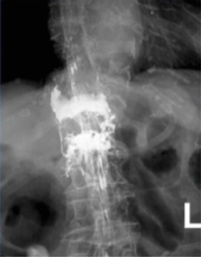
Figure 39-18. Intravertebral cement extravasation—AP view (most likely due to medial needle placement violating pedicle).
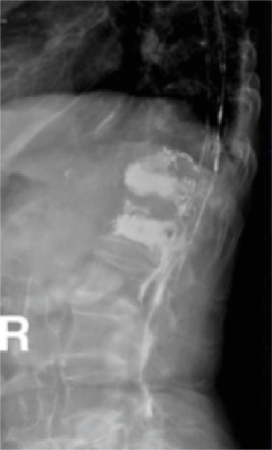
Figure 39-19. Lateral view of same patient.
POSTPROCEDURE FOLLOW-UP
• To achieve homeostasis, manual pressure is applied to the skin after the needles are removed.
• Bacteriostatic cream and bandages are used to cover the puncture sites.
• Patients are logrolled with extreme care from the operating table to the stretcher to avoid new fractures.
• Vital signs, and especially neurological monitoring, should be evaluated frequently during patient’s stay.
• Patients may start ambulation after complete recovery that may take about 1 hour.
• Patients are discharged home after ambulating, and are instructed to contact an emergency 24-hour service in case of developing signs of possible complications.
POTENTIAL COMPLICATIONS AND PITFALLS
• The majority of complications are mild, transient, and self-limited.
• Potential complications include hemorrhage; infection; spinal stenosis; death; pulmonary emboli; local trauma to nerve roots, spinal cord, or kidney; and fracture of the lamina, pedicle, or ribs.
• Transient radiculopathy has been reported in 3% to 6% of patients and has been successfully treated in the majority of cases with steroids and anti-inflammatory medications.14
• In the early years of performing vertebroplasty, a higher incidence of cement extrusion (30%-80%) was noted, probably related to the low viscosity of cement (used in the initial studies) and the high pressure required to inject cement into the cancellous matrix of the vertebral body.15,16
• Using higher viscosity filling/stabilizing materials may reduce this risk.
• There are many routes by which cement may leak from a vertebra: paravertebral leakage, venous leakage, or leakage into the spinal canal and intervertebral foramen.17,18 Dispersing of the cement in the bony structures shows nonuniform margins. Therefore, noticing cement with smooth and uniform margins should raise the suspicion of cement extrusion into the paravertebral muscles. This can cause severe localized pain due to the exothermic reaction during polymethylmethacrylate cement curing and the effect of the mass of cement on muscle motion.
• Leakage of cement into the venous circulation can produce generalized toxic reactions and, when entering the inferior vena cava, possibly life-threatening pulmonary embolization.19–24 Leakage of cement into the epidural space may compress the spinal cord and/or nerve roots.25–29 The incidence of this complication is low (1%-2% of the cases), and it is usually self-limiting.
• A postoperative CT scan is recommended if the physician suspects cement extrusion. If one is suspecting this complication, we suggest a short course of oral steroids, anti-inflammatory medications, or an epidural steroid injection. Only in extreme cases, a decompressive laminotomy or foraminotomy may be required.
![]() Intradiscal cement extrusion is seen in 5% to 10% of the cases.
Intradiscal cement extrusion is seen in 5% to 10% of the cases.
![]() The concern of increased risk of adjacent fractures is currently unsubstantiated but the risk was shown to be reduced by using Cortoss®.
The concern of increased risk of adjacent fractures is currently unsubstantiated but the risk was shown to be reduced by using Cortoss®.
![]() Rib fractures during these procedures have been previously reported and are related to the positioning of the patient.
Rib fractures during these procedures have been previously reported and are related to the positioning of the patient.
• The AP view of the intravertebral cement extravasation can be seen in Figure 39-18. (Most likely due to medial needle placement violating pedicle.)
• The lateral view of the same patient can be seen in Figure 39-19. Note: Cement extravasation in thecal sac.
Posterior Leakage
• More complications arising from the needle placement being too medial causing cement being deposited in the posterior versus the anterior of the vertebral body (see Figure 39-20A-C).
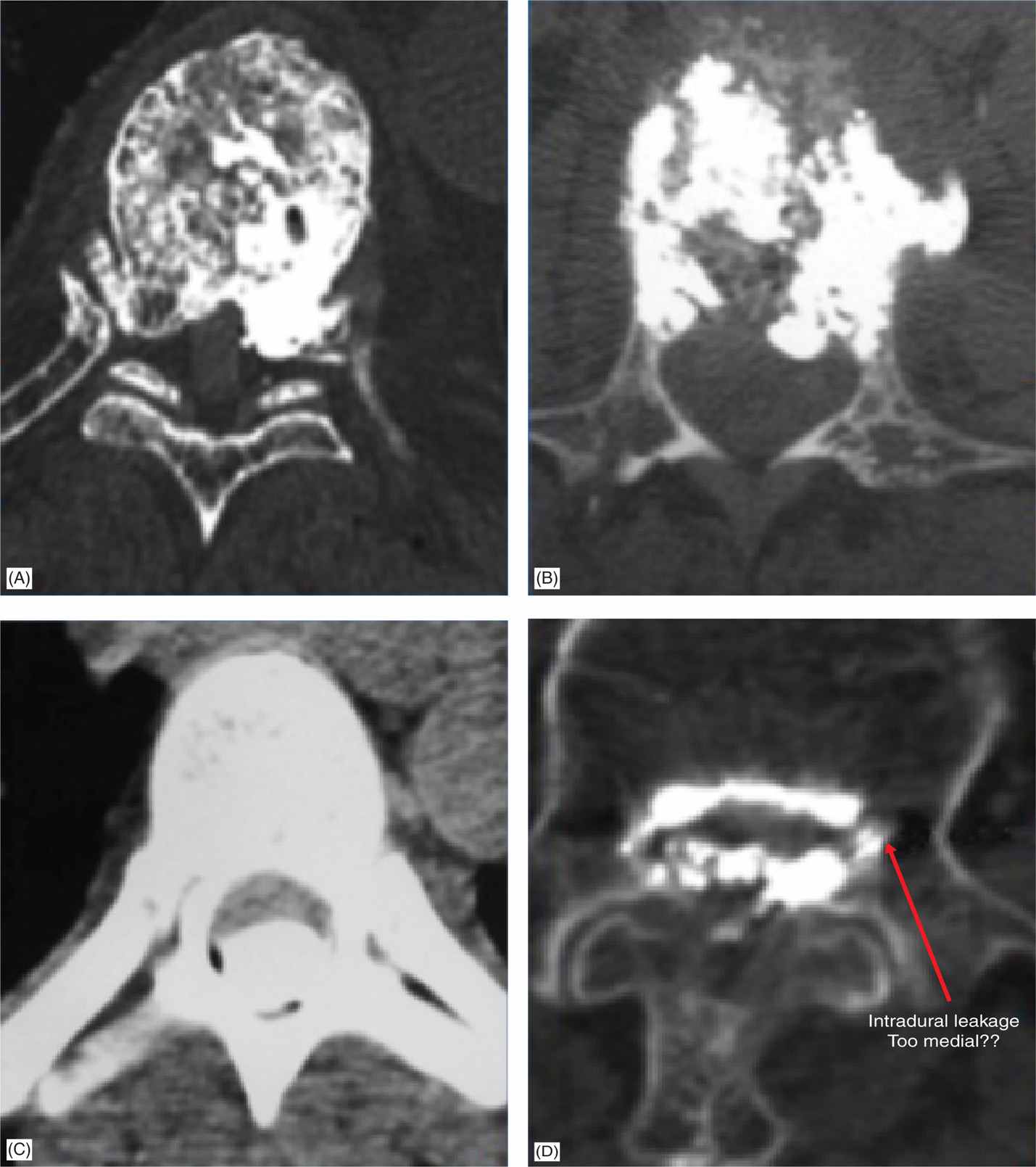
Figure 39-20. (A-D) Complications from cement deposited in posterior vertebral body.
• Note the intradural leakage from taking a needle position too medial (Figure 39-20D).
Massive Pulmonary Embolism
• Insufficient polymerization of the injected cement, most likely due to an unbalanced monomer-to-powder ratio.
• Aortic embolism (Figure 39-21)
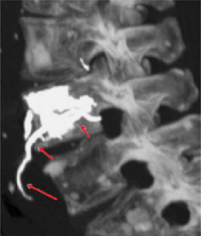
Figure 39-21. Aortic embolism.
• Right laterovertebral artery
• 3 images of 3 different complications:
![]() L4 radiculopathy where nerve root is severed at the dorsal horn (Figure 39-22)
L4 radiculopathy where nerve root is severed at the dorsal horn (Figure 39-22)
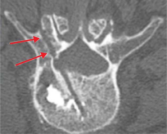
Figure 39-22. Nerve root severed at the dorsal horn.
![]() Pedicle fracture (Figure 39-23)
Pedicle fracture (Figure 39-23)
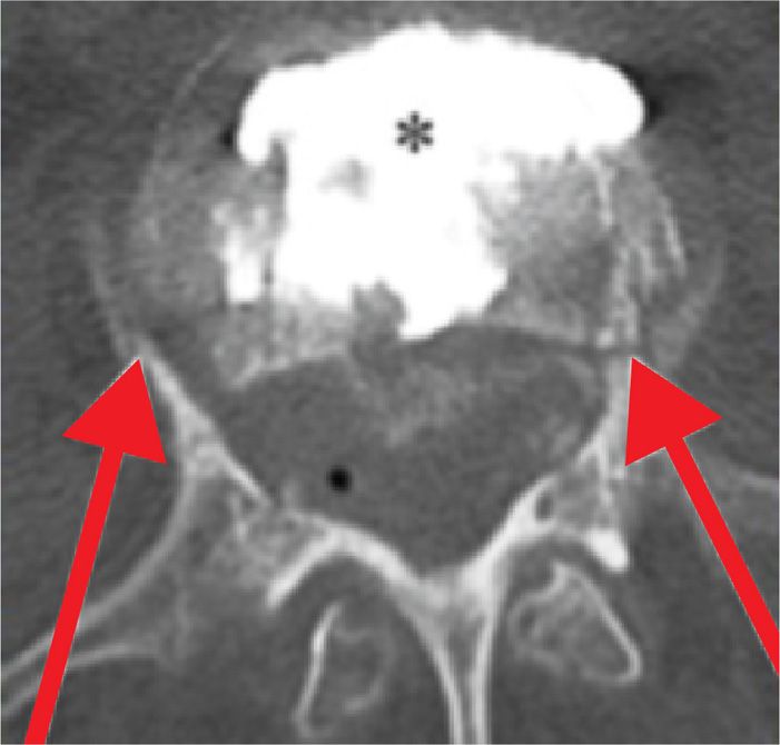
Figure 39-23. Pedicle fracture.
![]() Cement deposited in the spinal canal and none in the vertebral body
Cement deposited in the spinal canal and none in the vertebral body
• PMMA embolization and PMMA embolism into the lungs
• PMMA embolization in cerebral circulation after vertebroplasty in a patient with patent foramen ovale
CLINICAL PEARLS
• Vertebroplasty and vertebral augmentation techniques like balloon kyphoplasty are minimally invasive vertebral augmentation procedures involving injection of polymethyl methacrylate cement (or other bioactive material) under radiologic control into a fractured vertebral body. They strengthen the bone and improve the intense pain caused by fracture secondary to osteoporosis, metastasis, or trauma and refractory to conservative therapies such as analgesic use, bed rest, and bracing.30
• Although the main indication for percutaneous vertebroplasty and vertebral augmentation technique is painful vertebral compression fracture, osteoporotic patients may also suffer from other sources of spine pain like spinal stenosis, disc degeneration and facet arthropathy that need to be treated separately.
• The cause and source of every compression fracture needs to be evaluated. In patients with known history of cancer and those with no previous history of osteoporosis, it is prudent to perform bone biopsy prior to injecting cement into the fracture.
• Both percutaneous vertebroplasty and vertebral augmentation techniques offer therapeutic benefit, significantly reducing pain and improving mobility in patients with vertebral fracture without significant differences in terms of outcomes.
• Both percutaneous vertebroplasty and vertebral augmentation techniques rely on imaging devices like C-arm fluoroscopy and CT scan for safe placement of needle and injection of stabilizing material. Injection of cement has to be performed under real-time imaging, in order to avoid detrimental cement leakage.
• Best suited physicians for performing these procedures are interventional pain or spine physicians with advanced knowledge of anatomy and experience in performing percutaneous image-guided procedures.31
• The most crucial part of procedure is correct and safe placement of needle and then, injection of stabilizing material in the target zone. Fluoroscopy has definite shortcomings: needle placed in blind spots (as depicted in red triangles) will be viewed (in both AP and lateral) as it is placed in the vertebral body (Figure 39-24).
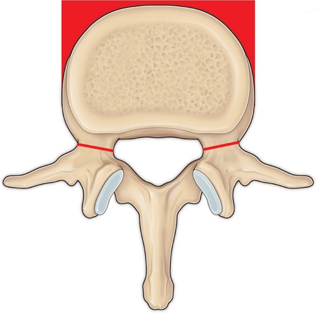
Figure 39-24. Needle guide for vertebral augmentation.
• It is of utmost importance to advance the needle while checking AP and lateral view frequently to avoid deviation of needle too medially or too laterally. As long as the needle has not passed the pedicle into vertebral body on the lateral view, in the AP view it should not violate the medial pedicular (facet) line. The AP and lateral views below depict the correct placement of needle in pedicle, prior to entering the vertebral body (Figure 39-25A, B).
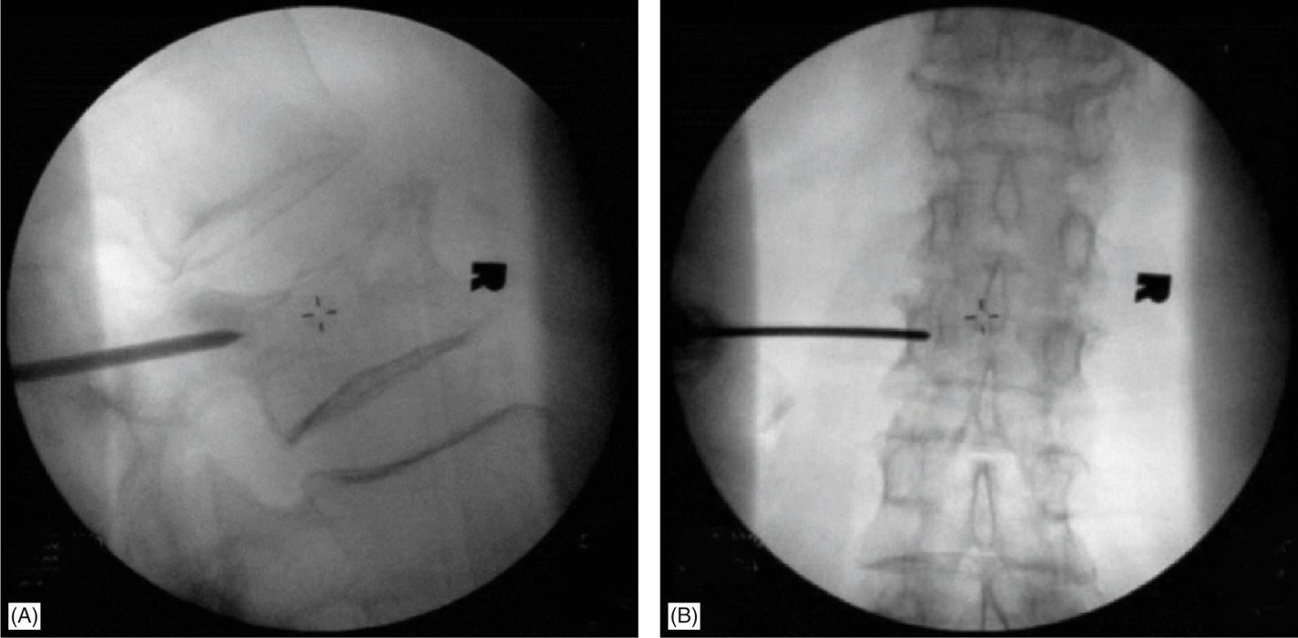
Figure 39-25. (A, B) AP and lateral views for correct needle placement.
• Deviation of needle medially (toward spinal canal) will have more serious consequences and should be avoided by judicious use of imaging. The following diagrams show the needle trajectories that are off the safe pathway (Figure 39-26A, B).32
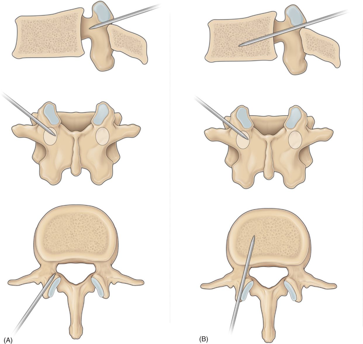
Figure 39-26. (A, B) Unsafe needle trajectories.
ACKNOWLEDGEMENT
The authors wish to thank Daniel E. Dolen for his assistance in preparing this manuscript and for providing his artistic skill for our anatomical drawings for this chapter.
Related posts:


Stay updated, free articles. Join our Telegram channel

Full access? Get Clinical Tree


