Fig. 11.1
Top panel (a). DDD pacemaker. Atrial rhythm is paced at 60 bpm. Spontaneous QRS with right bundle branch morphology occurs after 180 ms that inhibits ventricular pacing. This is called atrial-driven rhythm. Bottom panel (b): spontaneous sinus rhythm is present; each P wave is followed by a ventricular stimulus at the end of the programmed AV delay (120 ms) that captures the ventricular myocardium. The QRS morphology is left bundle branch block with superior axis, typical of right ventricular apical pacing
The basics of single chamber (SSI), more often ventricular (VVI) PM, are more simple: the ventricle is paced at the end of the programmed escape interval, or basic rate, when nonsensed signal occurs within this time. In rate-responsive PM, either VVI or DDD, the stimulation rate is increased during effort according with sensors [1].
11.2.2 Most Important, Basic Programmable Functions in a Pacemaker
(a)
Lower rate: it is the rate below which the pacemaker will stimulate the heart. If spontaneous activity is higher than the programmed lower rate, pacemaker output is inhibited. If programmed rate is higher than spontaneous rate and PM spikes are not visible, a malfunction is present, usually oversensing. The only exception is the presence of a “hysteresis” algorithm programmed on.
(b)
Hysteresis: if this function is activated, the lower heart rate below which the PM will start the stimulation is different from the programmed pacing lower rate. For example, if hysteresis is programmed at 40/min and lower rate at 70/min, the PM will start the stimulation only if spontaneous heart rate drops below 40/min, but stimulation rate will be 70/min. The PM will check periodically the presence of spontaneous rate between 40 and 70/min.
(c)
Rate-responsive pacing: the stimulation rate is increased when activity sensors detect patient movements (accelerometers). Respiratory activity sensors or other algorithms are also able to increase the basic pacing rate.
(d)
Upper rate: it is the maximum stimulation rate either in case of atrial-driven or sensor-driven stimulation. If the PM stimulates at a rate higher than the programmed upper rate, a hardware/software malfunction is present. This can happen in case of unprotected exposition to strong electromagnetic fields, such as magnetic resonance imaging.
(e)
Algorithms to reduce ventricular pacing: in order to reduce unnecessary ventricular pacing, several algorithms are present in modern dual chamber PM. Most commonly, only the atrium is stimulated (AAI mode) if atrioventricular conduction is preserved; when one or two (depending on the model and device programming) consecutive A-V blocks occur, the mode of stimulation automatically changes to atrioventricular pacing (DDD mode). Other algorithms prolong the programmed A-V interval up to 400 ms to detect if spontaneous A-V conduction is present. When these algorithms are activated, it is sometimes difficult to understand if the PM is working normally or not, for example, in case of single atrial beats without any ventricular activity; this can be a normal behavior of the device, when followed by DDD pacing, but can be expression of ventricular oversensing. Knowledge of the device programming, PM interrogation, or real-time telemetry can be necessary for the diagnosis.
(f)
Pacing voltage: this is the voltage of PM stimulus. If it is programmed below the ventricular pacing threshold, spikes will be ineffective leading to an exit block.
(g)
Pulse duration: this is the duration of PM stimulus. If it is programmed too short, spikes could be ineffective leading to an exit block.
(h)
Autocapture: this algorithms automatically reduce PM output energy to values just above the ventricular pacing threshold. In case the delivered stimulus doesn’t capture the ventricle, a second high-energy stimulus is provided: this is a normal behavior of modern PM and not a malfunction.
(i)
Mode switch: when this algorithms are activated in dual chamber PM, the mode of stimulation automatically switches from DDD(R) to VDI(R) when an atrial tachycardia/fibrillation is detected. If atrial arrhythmia terminates, the mode of stimulation will return from VDI to DDD [1].
11.3 What Cardiologists Should Know
Cardiologists must be familiar with basic PM functions, mode of stimulation, PM algorithms, and interpretation of ECG recordings in PM patients. Modern PMs are very complex, fully programmable devices, with a lot of therapeutic and diagnostic capabilities. PM interrogation, evaluation of battery and lead data, analysis of real-time telemetry, and stored data are necessary for the final evaluation of PM functions. It would be desirable that cardiologists were trained and capable to use at least basic functions of PM programmers and the meaning and utilization of the following:
(a)
Magnet: the application of a magnet above the PM pocket induces asynchronous pacing (VOO or DOO in single chamber or dual chamber PM, respectively). In case a PM is apparently not working (because spikes are not evident) but bradycardia (below lower rate, including hysteresis) is present, it is useful to apply a magnet on the PM. If PM spikes appear and capture the ventricle, oversensing inhibiting PM stimulation is likely. When necessary, in this cases magnet function is also useful for emergency treatment of the bradycardia.
(b)
ERI: this is a message of “low battery charge” (Elective Replacement Indicator), meaning that the device will soon (usually after about 3 months) reaches the complete battery depletion, or EOL (End Of Life); ERT (Elective Replacement Time) and EOS (End Of Service) are synonymous of ERI and EOL, respectively, used by some manufacturers.
(c)
Pacing impedance: this value is normally in the range between 350 and 900 Ω. Pacing impedance is influenced by the integrity of pacing circuit (conductors and insulation), by the lead model (i.e., active or passive fixation, steroid eluting or normal electrodes), and by electrode endocardial contact surface. When pacing impedance drops below 250 Ω, an insulation failure of the lead is likely. When pacing impedance is above 1500–2000 Ω (depending on the lead model), a conductor fracture or a connection defect is possibly present. In case of an abnormal pacing impedance in bipolar pacing and sensing configuration, PM reprogramming to unipolar pacing and sensing is recommended.
All cardiologists involved in emergency evaluation of PM patients should be trained to recognize the most commonly PM malfunctions, i.e., undersensing, oversensing, and exit block [1–3].
11.3.1 Undersensing in Cardiac Pacemakers
Undersensing occurs when the PM fails to sense the spontaneous atrial or ventricular activity. In this case the PM will ignore the spontaneous activity and pace the heart at the programmed rate as if the patient had no rhythm. This results in the so-called “asynchronous” pacing, that is, pacing competitive with spontaneous cardiac activity. Ventricular pacing during the vulnerable period of cardiac cycle (T wave) can occur, triggering ventricular arrhythmias including ventricular fibrillation [1–3].
An example of ventricular undersensing is illustrated in Fig. 11.2.
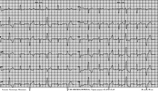
Fig. 11.2
VVI pacemaker. Spontaneous rhythm is present interrupted by premature beats of different morphology. At careful ECG inspection, small pacemaker spikes (bipolar) precede the QRS with left bundle branch morphology and left axis deviation. Other spikes follow spontaneous QRS in random sequence (asynchronous pacing). Undersensing of ventricular activity is present
11.3.1.1 Causes of Undersensing
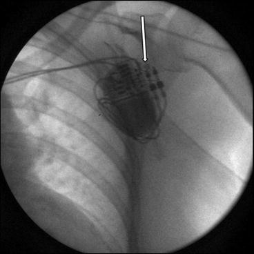
Causes of undersensing include lead failure, pacemaker failure, and environmental and physiologic changes. Lead failure is the most frequent cause of under- and oversensing in current CIEDs. Both insulation failure and lead fracture are able to induce undersensing, so it is pivotal to interrogate the pacemaker to evaluate pacing impedance. An increase of pacing impedance > 2000 Ω is diagnostic of conductor damage. A decrease of pacing impedance below 250 Ω is diagnostic of insulation failure. A connection defect is usually associated with a high pacing impedance, >3000 Ω, and this must be distinguished from conduction fracture in the presence of high pacing impedances. To identify a connection defect, chest X-ray is useful, as it can show the lead connector incompletely inserted into the PM head. An example of connection defect is illustrated in Fig. 11.3.
 Management of Arrhythmic Patients in the Emergency Department: General Principles
 Syncope: First Evaluation and Management in the Emergency Department
Acute Management of Patients with Arrhythmias and Non-cardiac Diseases: Metabolite Disorders and Ion Disturbances
Syncope: First Evaluation and Management in the Emergency Department
Acute Management of Patients with Arrhythmias and Non-cardiac Diseases: Metabolite Disorders and Ion Disturbances
 Acute Management of Arrhythmias in Patients with Channelopathies
 Atrial Flutter and Fibrillation in the Emergency Setting
 Wide QRS Complex Tachycardia in the Emergency Setting


Related posts:
Management of Arrhythmic Patients in the Emergency Department: General Principles
Syncope: First Evaluation and Management in the Emergency Department
Acute Management of Patients with Arrhythmias and Non-cardiac Diseases: Metabolite Disorders and Ion Disturbances
Acute Management of Arrhythmias in Patients with Channelopathies
Atrial Flutter and Fibrillation in the Emergency Setting
Wide QRS Complex Tachycardia in the Emergency Setting
Stay updated, free articles. Join our Telegram channel
Full access? Get Clinical Tree
