Figure 15.1 Short-axis view in a phantom model. (a) This is a short-axis view with picture-in-picture of a phantom gel being cannulated. On the ultrasound image, the vessel appears as a circle in cross-section. The needle is oriented perpendicular to the transducer. (b) Demonstration of the needle path in a phantom vessel.
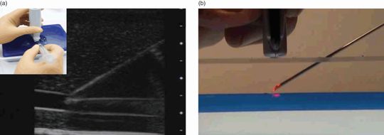
Figure 15.2 Long-axis view in a phantom model. (a) This is a long-axis view with picture-in-picture of a phantom gel being cannulated. The needle tip appears at the right upper portion of the ultrasound image. The needle tip is then tracked as it follows through the tissue down to the vessel which appears as a tubular structure. The needle is oriented parallel to the transducer. (b) Demonstration of the needle path in a phantom vessel.
Once the vessel is identified, grayscale compression (gentle pressure compression) is utilized in order to distinguish veins from arteries. With gentle pressure with the transducer, veins should collapse, while arteries should stay patent (Figure 15.3). This is most easily performed in the short-axis view of the blood vessel. It is important to note that with sufficient pressure some arteries will collapse, especially with smaller-diameter vessels and in smaller infants/children. Another means by which one can distinguish artery from vein is color Doppler, which shows constant flow through a vein, compared with the pulsations from an artery.
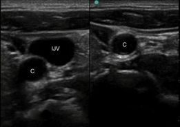
Figure 15.3 Graded compression. Gentle pressure is applied with the transducer to distinguish arteries from veins. This split-screen image shows the internal jugular vein (IJV) and carotid artery (C) on the left, precompression. On the right, post-compression image shows the internal jugular vein collapsed and not visible, while the thicker-walled carotid (C) stays patent.
Ultrasound-guided procedure
Long-axis (in-plane) approach
The needle is oriented parallel to the long-axis of the transducer (Figure 15.2). The needle is immediately adjacent to the center of the smaller width of the transducer. It is important to note the orientation of the probe indicator. If the indicator is oriented towards the operator, the needle will be visualized as entering the left-hand side of the ultrasound image.
Short-axis (out-of-plane) approach: approximating needle entry
In the short-axis approach, one must approximate needle entry (Figure 15.4). Once the vessel is identified on the ultrasound image, the depth can be readily determined by the markings on the right-hand side of the image. In utilizing the Pythagorean theorem, the depth should equal the distance away from the transducer:
It is important to note that this is only true if the needle is at a 45° angle to the skin. Errors in needle placement may lead to under- or over-estimation of the target structure (Figure 15.5). Needle redirections may be performed under real-time guidance. Limitations are that the needle is not visualized until it actually enters the vessel. The needle tip, or ring-down artifact, will only be visualized as it arrives at and penetrates the targeted structure, thereby being “out of plane.”
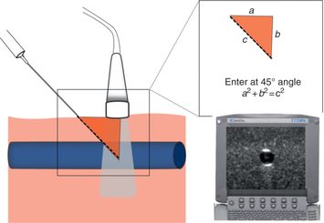
Figure 15.4 Approximating needle entry. In the short-axis plane, the needle enters at a 45° angle to the skin, at a distance away from the transducer that equals the depth of the target structure. This is true because of the Pythagorean theorem (a2 + b2 = c2). Depth can be determined from the depth markers on the right side of the ultrasound image (arrow).
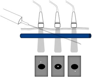
Figure 15.5 Errors in needle placement. If the needle is placed too close to the transducer, the needle will be above the target vessel. In contrast, if the needle is placed too far away from the transducer, the needle will be below the target vessel. Illustration by Laura Berg, MD.
Short-axis approach: following the tip
Some practitioners feel uncomfortable not being able to visualize the needle tip until it reaches the target. Therefore, a new method was developed called “following the tip.” The needle is oriented in the short-axis, or perpendicular to the transducer. The needle enters the skin immediately adjacent to the transducer (Figure 15.6a). As the needle/catheter is advanced, the transducer is moved away from the operator at the same velocity (Figure 15.6b). Therefore, the ultrasound beam tracks the needle tip throughout its course, until it reaches the target. It is important to note that this method requires significant manual dexterity and presumably more practice than the other methods.
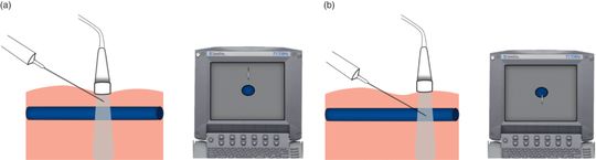
Figure 15.6 “Following the tip.” The needle is oriented perpendicular to the transducer, immediately adjacent to its center. The corresponding ultrasound image is a cross-section of the targeted vessel, with the needle tip above it (a). As the needle is advanced, the transducer is moved away from the operator at the same velocity. The corresponding ultrasound image ultimately shows the needle tip penetrating the target vessel (b). In this approach, the needle tip is visualized along its entire path, in the short-axis view. Illustration by Laura Berg, MD.
The oblique approach
This is a novel method that is a combination of the short-axis and long-axis views for vessel cannulation (Figure 15.7). The vessel is first identified in the short-axis, and then the transducer is rotated almost midway between the short-axis and long-axis. Vessels appear as slightly elongated, and the needle is visualized along its entire path of entry. Further research needs to be performed regarding the success of the oblique method in comparison to the other, well-established techniques.
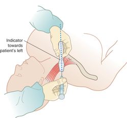
Figure 15.7 The oblique approach. The vessel is first identified in the short-axis. The transducer is then rotated midway between short-axis and long-axis (rotation of 45°). Artwork created by Emily Evans © Cambridge University Press.
Confirmation of placement, securing the line
Prior to penetrating the blood vessel, one may visualize “tenting of the blood vessel” (Figure 15.8a) and the “ring-down” artifact (Figure 15.8b) of the needle as it enters the vessel lumen. Blood vessel cannulation may be confirmed by visualizing needle placement in two planes, the visualization of a blood flash in the catheter, and the ability to flush saline. Once this occurs, ultrasonography may be discontinued and the catheter secured. Once the needle tip is in the vessel, the needle must be advanced far enough such that the catheter is in the vessel. Once this position is obtained, the catheter can be moved and advanced forward successfully.
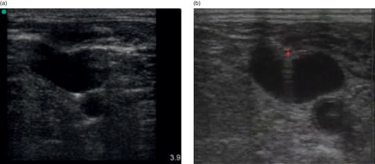
Figure 15.8 Short-axis confirmation of line placement. (a) Prior to penetration of the blood vessel, the vessel exhibits deformation, or “tenting,” as is evident in this ultrasound image of an IJ line placement. (b) Once the needle enters the blood vessel, one can visualize the needle tip and the “ring-down” artifact (arrow) that arises from the metal of the needle.
In the traditional “landmark” or “blind” technique of central line placement, it is imperative that the syringe be aspirated during the time of needle advancement into the vein. Having blood returning into the syringe denotes successful cannulation of the central vein. By contrast, with ultrasound guidance, a syringe does not necessarily even need to be attached to the needle.
It is important to note that, since IV placement occurs at a 45° angle in the needle-approximation technique, smaller-gauge catheters have the potential to kink. In order to maintain the angle of entry, one may prop the catheter hub with 2″×2″ gauze prior to securing the catheter against the skin.
Training and education
The dynamic or real-time ultrasound guidance involves a steep learning curve and multiple steps to become proficient in it. The reward of learning the procedure is in the precision that it provides in guiding a needle into the desired location. Commercially available phantom models simulate blood vessels in order to teach hands-on vascular access (Figure 15.9a,b), prior to attempting to place the IV in a patient. Other less-expensive, home-made phantoms may be prepared which are effective as well (Figure 15.9c). It has been suggested that when comparing the different approaches to ultrasound-guided vascular access, the short-axis (out-of-plane) approach is the easiest to teach and learn.
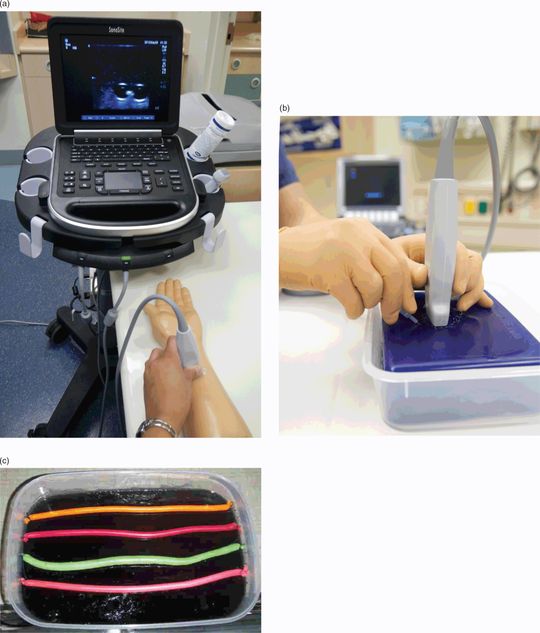
Figure 15.9 Phantoms for vascular access instruction. (a, b) Commercially available phantoms. (c) A home-made version of a training phantom. This particular version consists of store-bought gelatin with toy balloons filled with colored liquid. When the gel is chilled in the refrigerator, the balloons are suspended in the center of the gelatin-filled container.
Specific scanning techniques
Femoral vein
The femoral vein is one of the preferred sites for central venous cannulation in the cardiac arrest/CPR situation.
Anatomy
In most patients, the femoral nerve is lateral to the femoral artery, and the femoral vein medial to the artery (Figure 15.10a). However, it has been shown by ultrasound that there are variations in the anatomic relationship of the femoral vein and artery.

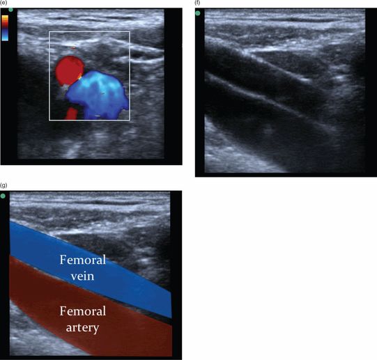
Figure 15.10 Femoral vein. (a) Femoral vein anatomy. The femoral vein is larger in diameter than the artery, and typically lies medial to the femoral artery. Artwork created by Emily Evans © Cambridge University Press. (b) Transducer placement in the inguinal region for femoral vein access. The leg may be flexed forward or held in extension to improve visualization. Note that the sterile preparation was removed in order to demonstrate proper transducer placement. (c) Ultrasound image of the short-axis view of the femoral vessels. (d) Associated structures visualized by ultrasound in the short-axis view, including the psoas muscle and the femoral nerve, femoral artery, and femoral nerve. (e) Femoral vessels with color Doppler. (f) Ultrasound image of the long-axis view of the femoral vein. (g) Associated structures visualized by ultrasound in the long-axis view. Illustration by Laura Berg, MD.
Technique
For femoral access, the transducer should be placed in the inguinal region (Figure 15.10b). In order to obtain the short-axis view, the transducer should be oriented with the indicator towards the proceduralist’s left side (Figure 15.10c,d). In the majority of patients, the femoral artery will lie to the left of the femoral vein. However, it is important to interrogate both the patient’s right and left sides since there is anatomic variation with regards to the relationship between femoral artery and vein. In order to obtain the long-axis view, the transducer should be oriented with the indicator towards the patient’s head (Figure 15.10f,g).
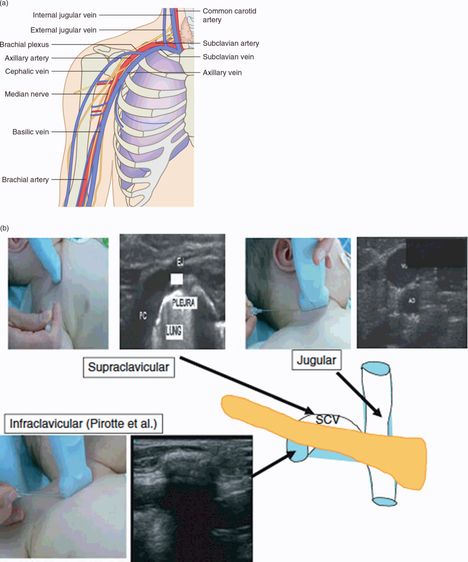
Subclavian vein
The subclavian vein is the preferred site for central venous cannulation for sepsis, since the femoral site is more at risk for infection. The subclavian vein is often the preferred site of central line placement in children, due to space constraints.
Anatomy
The axillary vein courses through the pectoralis muscle in a medial and superior direction. Once the vein crosses below the clavicle it is known as the subclavian vein (Figure 15.11a).