Figure 17.1 Anatomy of the lumbosacral spine. Artwork created by Emily Evans © Cambridge University Press.
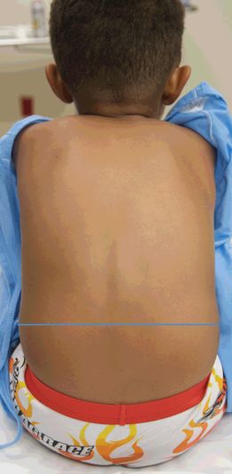
Figure 17.2 Tuffier’s line. The imaginary line that connects the right and left iliac crests. This line estimates the location for L4–5, which is the ideal location for a lumbar puncture to be performed by traditional methods.
Technique
Transducer selection and orientation
A linear-array transducer (5–10 MHz) is the preferred transducer for performing ultrasound-assisted lumbar punctures, providing superior resolution at shallow depths (Figure S3.3a). In neonates, the pediatric linear transducer, or “hockey stick,” is appropriate but may be too small for older children. In obese patients, the curvilinear transducer may provide additional resolution of deeper structures and should be considered as an alternative to the linear transducer (Figure S3.3b).
Ultrasound images should be obtained in two views: in the longitudinal and transverse planes. The longitudinal plane includes two approaches: the median and paramedian approaches. In the median longitudinal approach, the transducer is placed directly over the posterior spinous processes. In the paramedian longitudinal approach, the transducer is off midline; therefore, there is less interference from the spinous processes, providing a better acoustic window. In addition, the paramedian approach allows for a more clear distinction between the ligamentum flavum and the dura mater.
Patient position and preparation
There are two generally accepted positions for performing ultrasound-guided lumbar punctures. Patients may either be seated upright (Figure 17.3a), or placed in a lateral recumbent position (Figure 17.3b). In both positions, hip flexion will increase the interspinous spaces. Contrary to what was previously thought, neck flexion actually does not affect the interspinous spaces, and should be avoided. For infants in the seated position, rolling a small towel and placing it under the knees may achieve hip flexion. In the lateral recumbent position, the knees should be drawn up to the chest and the shoulders rotated forward.
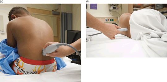
Figure 17.3 Positioning for ultrasound-guided lumbar punctures. (a) Seated positioning for ultrasound-guided lumbar puncture. (b) Lateral recumbent positioning for ultrasound-guided lumbar puncture.
Ultrasound imaging
Ultrasound can identify a number of anatomical structures of the pediatric spine. If the clinician is identifying solely the bony landmarks and the interspinous spaces, a shallow depth of a few centimeters is sufficient. For identification of the dura and deeper structures, the depth will need to be increased in order to allow for better visualization. The posterior spinous processes are covered by continuous layers of hyperechoic skin, hypoechoic subcutaneous tissue, and a hyperechoic layer of the thoracolumbar fascia and the supraspinal ligament. To identify the specific lumbar vertebra, the transducer can be moved inferiorly to the sacrum and upward towards L5. Sonographically, the supraspinous ligament will pass over L5 and then curve inferiorly in order to insert onto the sacrum.
When performing a sonographic evaluation of the spine and spinal cord, both transverse and longitudinal views should be obtained. The transducer should be oriented perpendicular to the spine (Figure 17.4a) in order to obtain the short-axis or transverse view of the spinal cord (Figure 17.4b,c). In order to obtain the longitudinal, or long-axis view of the spinal cord, the transducer should be oriented parallel to the spine (Figure 17.5a). There are two methods of obtaining the longitudinal view – the midline sagittal plane, and the paramedian plane (off midline). In the midline sagittal plane, the spinous processes are discrete, hyperechoic, curved lines that are separated by an echogenic interspinous spaces. The posterior vertebral column is shaped like a “Y,” where the laminae are the arms of the “Y” and join to form the posterior spinous process (Figure 17.5b,c). In the paramedian plane (off midline), more anatomic elements are seen (Figure 17.6a,b). There is a small window between the spinous processes, and the acoustic shadow resulting from bone represents the lamina, rather than the posterior spinous process. Deeper in the interspinous space there is a hyperechoic line representing the ligamentum flavum and dura mater, separated by the epidural space (Figure 17.6c). Of note, it may be difficult to distinguish the ligamentum flavum and dura mater; however, sonographically the dura will predominate. Below the dura is the hypoechoic subarachnoid space.
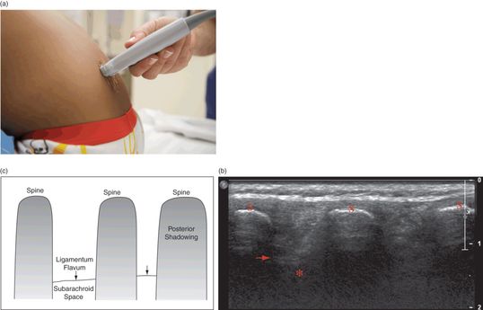
Figure 17.4 Spinal imaging, transverse view. (a) Transducer placement perpendicular to the spine. (b) Ultrasound of the transverse spine. Structures visualized by ultrasound include the spine (S) with posterior shadowing, the dura mater/ ligamentum flavum (arrow), and the subarachnoid space (*). (c) Illustration depicting these structures. Ultrasound image courtesy of Brian Coley, MD.
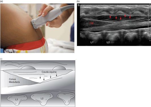
Figure 17.5 Spinal imaging, longitudinal view. (a) Transducer placement parallel to the spine. (b) Ultrasound of the longitudinal spine. Structures visualized by ultrasound. The conus medullaris (CM) and the cauda equina (arrows) can be easily visualized in this image. Ultrasound image courtesy of Brian Coley, MD. (c) Illustration depicting these structures.
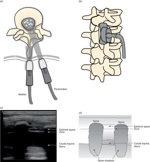
Figure 17.6 Spinal imaging, longitudinal (median and paramedian) views. (a) Vertebral body illustration of both the median and paramedian transducer placements. (b) Spinal anatomy illustration with median and paramedian approaches. (c) Ultrasound image of the paramedian transducer orientation. (d) Illustration depicting the structures visualized by ultrasound.
Related posts:


Stay updated, free articles. Join our Telegram channel

Full access? Get Clinical Tree


