Ultrasound-Guided Epidural Block (Caudal, Lumbar, and Thoracic), Truncal and Paravertebral Blocks in Children
Part 1: Introduction
Karen Boretsky
Paul E. Bigeleisen
Arvind Chandrakantan
Hadi S. Moten
Mihaela Visoiu
Epidural anesthesia continues to occupy a major role in pediatric regional anesthesia and represents almost half of the regional anesthetics in children younger than 3 years of age.1 In parallel with the use of ultrasound in all regional anesthesia, the use of ultrasound for guidance of epidural anesthesia has evolved quickly. When imaging and accessing the neuraxial structures in infants and children, it is imporTant to be aware of the developmental changes in the spine and the spinal canal that affect the ultrasound images.
The location of the spinal cord and dural sac within the spinal canal changes over time. During the development of the fetus in utero, the spinal cord extends the entire length of the spinal canal. This position ascends as the fetus develops, and in a newborn, the spinal cord extends as low as the L3 level with termination of the dura sac at the S4 level.2 As the child grows, the vertebral column grows faster than the spinal cord and the termination of the spinal cord moves to a progressively higher level, L1/L2 for the spinal cord and S2 for the dura at 1 year of age.2,3 These may be imporTant details to keep in mind in order to avoid complications such as inadvertent dural puncture and/or spinal cord trauma.3
The limited ossification of the pediatric vertebral column allows better visualization of the neuraxis in pediatric patients. The newborn skeleton is predominantly cartilage at birth and proceeds to deposit calcium and ossify progressively until puberty. This relative lack of ossification allows the easy penetration of ultrasound waves and a clear view of the neuraxial structures up until 3 months of age, after which ultrasound imaging becomes progressively more difficult.4 Around 9 months of age, the bony mass of the vertebral arches start to impose ultrasound shadows over the underlying structures, but anatomic information remains available in the ultrasound windows between adjacent vertebrae.
Ultrasound can be used in multiple ways to help with accessing the pediatric epidural space at different levels. Prepuncture scanning gives information about the location and depth of
the epidural space and adjacent structures. Alternatively, ultrasound imaging is used for realtime scanning to guide and direct the needle and catheter insertion into the epidural space. The ultrasound imaging is also used after the catheter or needle is inserted to confirm position.
the epidural space and adjacent structures. Alternatively, ultrasound imaging is used for realtime scanning to guide and direct the needle and catheter insertion into the epidural space. The ultrasound imaging is also used after the catheter or needle is inserted to confirm position.
References
1. Ecoffey C, Lacroix F, Giaufre E, et al. Epidemiology and morbidity of regional anesthesia in children: a follow-up one-year prospective survey of the French-Language Society of Paediatric Anaesthesiologists (ADARPEF). Paediatr Anaesth. 2010;20:1061-1069.
2. Johr M, Berger TM. Caudal blocks. Paediatr Anaesth. 2012;22:44-50.
3. Malas MA, Seker M, Salbacak A, et al. The relationship between the lumbosacral enlargement and the conus medullaris during the period of fetal development and adulthood. Surg Radiol Anat. 2000; 22:163-168.
4. Willschke H, Marhofer P, Bosenberg A, et al. Epidural catheter placement in children: comparing a novel approach using ultrasound guidance and a sTandard loss-of-resisTance technique. Br J Anaesth. 2006; 97:200-207.
Part 2: Single-Injection Caudal Approach to the Epidural Space
Karen Boretsky
Paul E. Bigeleisen
Arvind Chandrakantan
Hadi S. Moten
Mihaela Visoiu
 Background and indications: The relative popularity of epidural analgesia can be attributed to the relative ease with which the epidural space can be accessed via the sacral hiatus in infants and young children. A single injection of local anesthetic into the caudal epidural space, the “kiddie caudal,” is appropriate for most surgeries below the umbilicus and results in low complication rates and high success rates. Inadvertent spinal anesthesia, with an incidence of dural puncture of 0.19%,1 and perforation of adjacent viscera from improper position of the needle have, however, been reported. Ultrasound guidance offers a way to identify sacrum anatomy and perform caudal blocks in patients at risk for dural puncture (neonates and very small infants) and patients with difficult anatomy (older patients and patients with lumbosacral spinal dysraphism), potentially increasing the success rate and decreasing the rate of complications.2, 3and 4
 Anatomy: The sacrum is composed of five fused sacral vertebrae (Fig. 42.1). Its dorsal surface is convex and has a raised interrupted median crest with four (sometime three) spinous tubercles representing fused sacral spines. The posterior surface is formed by fused laminae. Below the fourth (or third) spinous tubercle, an arched sacral hiatus is identified due to failure of the fifth pair of laminae to meet, exposing the sacral canal, a continuation
 of the lumbar spinal canal. This caudal opening of the canal, or sacral hiatus, is covered by the sacrococcygeal ligament, which is an extension of the ligamentum flavum. The fifth inferior articulate processes project caudally and flank the sacral hiatus as prominent bony sacral cornua. The sacral canal contains the cauda equina (including the filum terminale) and the spinal meninges, epidural venous plexus, and adipose tissue. The lowest margin of the filum terminale emerges at the sacral hiatus and transverses the dorsal surface of the fifth sacral vertebra.
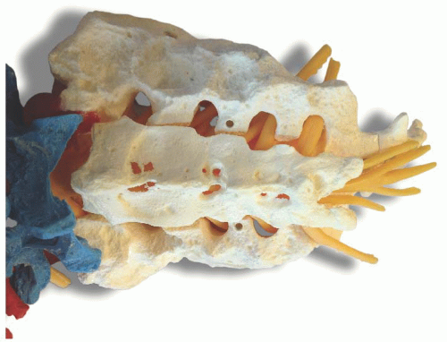 Figure 42.1. Sacrum and sacral hiatus. |
The sacrum structures are visualized in both the short axis (transverse) and the midline long axis (longitudinal).
Short axis: The two bony prominences of the sacral cornua appear as hyperechoic reversed U-shaped structures (Figs. 42.2 and 42.3). Two hyperechoic bandlike structures lie between the two cornua. The bandlike structure on top of the sacral cornua is the sacrococcygeal ligament, and the bandlike structure at the bottom is the bone of the dorsal surface of the anterior sacrum. The sacral hiatus is the hypoechoic region between the two bandlike structures.
Long axis: With the caudad edge of the transducer resting between the two cornua, the most prominent rounded hyperechoic structure observed is the bony prominence of the S4 spinous tubercle of the sacrum (Figs. 42.4 and 42.5). The sacrococcygeal ligament presents like a thick band beyond the end of the S4 spinous process, and the sacral hiatus is the hypoechoic region under the sacrococcygeal ligament.
 Patient position: Prone or lateral position with hips, knees, and neck flexed.
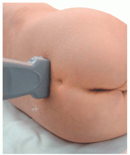 Figure 42.2. Probe position for transverse scan over sacrum. |
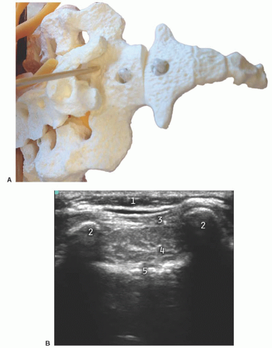 Figure 42.3. A: Sacrum with probe pointing to sacral hiatus. B: Transverse ultrasound view over sacrum. 1, subcuTaneous tissue; 2, sacral cornua; 3, sacrococcygeal ligament; 4, sacral hiatus; 5, floor of sacral canal. |
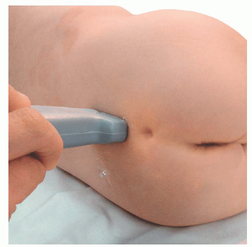 Figure 42.4. Probe position for sagittal scan over sacrum. |
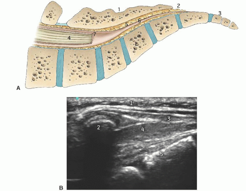 Figure 42.5. A: Sacral canal. 1, sacrum; 2, sacral hiatus; 3, coccyx; 4, cauda equine; 5, caudal canal; 6, filum terminale; 7, dura mater. B: Sagittal scan over sacral canal. 1, subcuTaneous tissue; 2, spinous tubercle of S4; 3, sacrococcygeal ligament; 4, sacral hiatus; 5, floor of sacral canal. |
 Transducer: 25- to 35-mm linear array oscillating at 6 to 13 MHz.
 Transducer orientation: Initially transverse over the two bony prominences of sacral cornua to identify sacrum structure. Then the transducer is rotated 90 degrees for real-time and/or confirmatory needle placement.
 Needle: 22G, 4- to 5-cm blunt needle.
 Local anesthetic: 1 mL/kg of ropivacaine 0.2% or bupivacaine 0.25%, maximum 20 mL.
 Technique: After proper disinfection of the skin, the sterile covered transducer is placed with a transverse orientation over the sacrum at the level where the sacral cornua can be palpated, the S4-S5 level. The sacral hiatus is identified as the hypoechoic space between the hyperechoic upside down U-shaped structures of the sacral cornua deep to the sacrococcygeal ligament. The probe is rotated to the longitudinal position while still visualizing the sacral hiatus, and the lower edge of the probe is placed at the level of the cornua. Under ultrasound longitudinal view, the needle is inserted through the sacrococcygeal ligament from a caudad to cephalad direction using an in-plane approach. The needle appears as a hyperechoic structure positioned in the sacral hiatus. The local anesthetic administration is observed in real time as a turbulence moving cephalad in the sacral hiatus. A final transition back to a transverse view may permit visualization of the local anesthetic between the sacrococcygeal ligament and the sacrum.
 Tips
Tips1. A prone position with rolls placed transversely under the hips achieves a flatter skin surface at the sacral hiatus area for the placement of the ultrasound transducer.
2. In the lateral position with hips, knees, and neck flexed, the dural sac shifts significantly cephalad, providing some safety margin to avoid dural puncture.3 The technique can be done under the ultrasound transverse view, using an out-of plane technique.
3. The optimal angle for needle insertion is between 10 and 38 degrees.5
4. The cHaracteristic “give” or “pop” can be detected when the sacrococcygeal ligament is penetrated.
5. The dosages for a single-injection caudal anesthesia are based on the site of surgery and the patient’s age and weight. In older children weighing more than 20 kg, the spread of local anesthetic after a single caudal injection is less reliable.
References
1. Beyaz SG, Tokgoz O, Tufek A. Caudal epidural block in children and infants: retrospective analysis of 2088 cases. Ann Saudi Med. 2011;31:494-497.
2. Chen CP, Tang SF, Hsu TC, et al. Ultrasound guidance in caudal epidural needle placement. Anesthesiology. 2004;101:181-184.
3. Koo BN, Hong JY, Kim JE, et al. The effect of flexion on the level of termination of the dural sac in paediatric patients. Anaesthesia. 2009;64:1072-1076.
4. Visoiu M, Lichtenstein S. 25 years of experience, thousands of caudal blocks, and no dural puncture. What happened today? Pediatr Anesth. 2012;22:304-305.
5. Park JH, Koo BN, Kim JY, et al. Determination of the optimal angle for needle insertion during caudal block in children using ultrasound imaging. Anaesthesia. 2006;61:946-949.
Part 3: Lumbar and Thoracic Epidural Catheters via the Caudal Approach
Karen Boretsky
Paul E. Bigeleisen
Arvind Chandrakantan
Hadi S. Moten
Mihaela Visoiu
 Background and indications: In the smallest patients, accessing the epidural space via a direct approach at the desired lumbar or thoracic level is technically challenging because of the diminutive size, the close proximity of vulnerable anatomic structures, and the fear of complications such as spinal cord trauma. Since 1988, a technique of accessing the epidural space via the sacral hiatus and threading a catheter cephalad to the desired dermatomal level is frequently used on infants and young children.1,2 Ultrasound imaging can be used to confirm placement of the needle and catheter through the sacral hiatus into the epidural space and to confirm passage of the catheter to the appropriate lumbar or thoracic level.
 Anatomy: The vertebral column contains 12 thoracic and 5 lumbar vertebrae bones (Fig. 42.6). Each vertebra is composed of a body anteriorly and an arch posteriorly, which enclose a canal housing the spinal cord. Protruding from the posterior midline of each arch is the spinous process, and extending laterally are the paired transverse processes. The spinal cord lies within the vertebral canal and is covered by three membranes. The two outermost layers, the dura mater and the arachnoid mater, are closely adherent. The space between the arachnoid mater, and the third layer, the pia mater, is the subarachnoid space,
 which contains the cerebrospinal fluid (CSF). The spinal cord is thickest at the thoracic level and decreases in size as it sheds nerve roots and tapers to its termination in a bundle of loose nerve roots called the cauda equina.3 The ligamentum flavum is a tough ligament that extends from C1 to S1 and connects the vertebrae to each other. The potential space created between the ligamentum flavum and the dura is the epidural space. The anatomy and sonoanatomy of the sacral hiatus and caudal canal are described earlier.
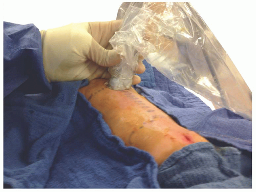 Figure 42.6. Probe position for transverse scan over thoracic spine for caudal catheter insertion in an infant. |
The lumbar and thoracic spine structures can be visualized in both the short-axis/transverse view (Fig. 42.7) and the long-axis/longitudinal view (Fig. 42.8).
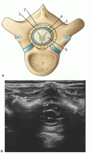 Figure 42.7. A,B: Transverse view of thoracic spinal canal. 1, posterior spinous process; 2, ligamentum flavum; 3, dura mater; 4, cerebrospinal fluid; 5, pia mater; 6, spinal canal; 7, vertebral body. |
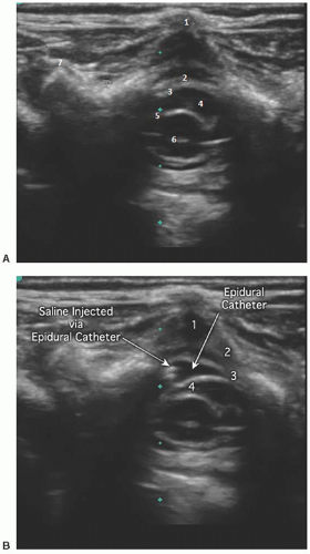 Figure 42.8. A: Thoracic epidural space before hydroexpansion. 1, posterior spinous process; 2, ligamentum flavum; 3, dura mater; 4, cerebrospinal fluid; 5, pia mater; 6, spinal canal. B: Epidural space after hydroexpansion. 1, ligamentum flavum; 2, dura mater; 3, cerebrospinal fluid; 4, spinal cord. |
Short axis: The spinous process is represented as a hyperechoic upside down V-shaped structure with an acoustic shadow below (Figs. 42.6 and 42.7). The spinal cord and dura are seen as two hyperechoic concentric circles deep to the spinous process. The hypoechoic spinal cord cased by the hyperechoic pia is represented by the innermost circle. The CSF is the hypoechoic concentric rim, and the dura is the outermost hyperechoic circle. The ligamentum flavum is difficult to visualize and usually appears indistinguishable from the dura. The ligamentum flavum can best be seen when separated from the dura by hydrodissection into the epidural space (Fig. 42.9).
Long axis: The long axis can be best visualized from a longitudinal paramedian view (Fig. 42.8 and 42.10). The spinous processes are now visualized as thick, slanted hyperechoic lines creating acoustic windows occurring at regular intervals. Between these acoustic windows, the elements of the spinal canal can be identified by layer. The dura mater is represented by the topmost (anatomically posterior) hyperechoic line between the acoustic windows. The hypoechoic layer beneath this represents the CSF, below which the hyperechoic pia mater is seen. The appearance of the neural element layer is dependent on the vertebral level being viewed. It appears as either a homogenous hyperechoic area representing the solid spinal cord or a bundle of hyperechoic linear structures representing the cauda equina. The vertebral bodies can be identified ventrally. The degree of acoustic shadowing cast by the spinous processes depends on the amount of ossification.
 Patient position: Prone with rolls placed transversely under the hips and shoulders to allow free excursion of the abdomen and flatten the lumbar curve (Fig. 42.11). Alternatively, a lateral position with the patient flexed forward and curled inward can be used.
 Transducer: 25- to 50-mm linear array oscillating at 6 to 17 MHz.
 Transducer orientation
Transverse: Visualize/locate sacral cornua.
Longitudinal: Visualize needle and catheter insertion.
Transverse: Confirm catheter tip location.
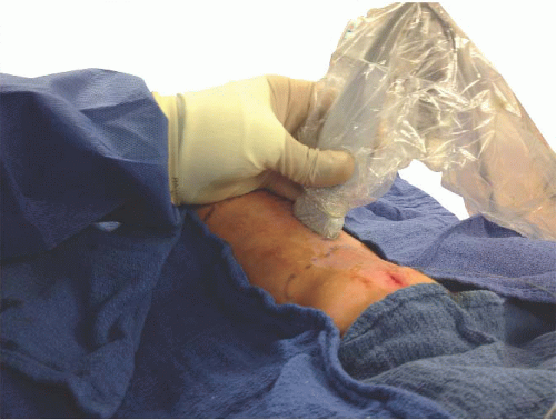 Figure 42.9. Sagittal probe position for thoracic epidural in an infant. |
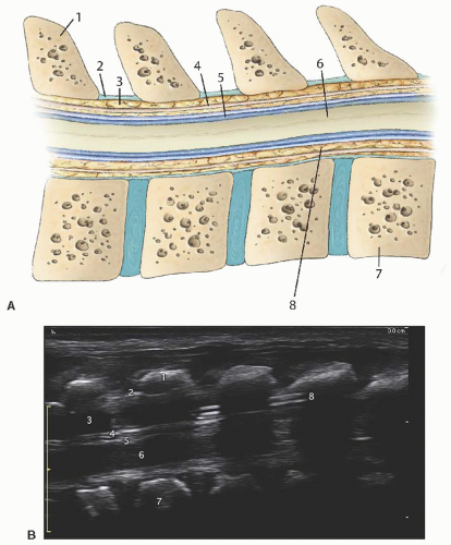 Figure 42.10. A,B: Sagittal view of thoracic spinal canal. 1, posterior spinous process; 2, ligamentum flavum; 3, subcuTaneous fat; 4, dura mater; 5, subarachnoid space; 6, spinal cord; 7, vertebral body; 8, epidural space. |
 Needle: 18G 5-cm Tuohy needle.
 Local anesthetic: 0.75 to 1 mL/kg of 0.2% ropivacaine or 0.25% bupivacaine followed by an infusion of 0.2 to 0.25 mg/kg/hr of ropivacaine or 0.25% bupivacaine (<4 months of age) or 0.4 to 0.5 mg/kg/hr of 0.2% ropivacaine or 0.25% bupivacaine (>4 months of age).
 Technique: Palpate and mark presumed position of the sacral cornua and desired lumbar or thoracic level for final catheter tip location. Using sterile technique, prep and drape a field to include the top of the intergluteal crease to the desired dermatomal level for tip. Using an ultrasound probe with a sterile sheath, locate the cornua (2 upside down U’s) and sacral hiatus via the short-axis view and rotate the probe 90° to a long-axis view while keeping the sacral hiatus in sight. Position the lower end of the probe at the level of the sacral cornua. Position and insert the needle as described above for the single-shot technique and carefully advance under ultrasound guidance. The needle will appear as a hyperechoic structure. Preservative-free normal saline (2 to 5 mL) is injected and used to confirm placement and open up the epidural space. With the probe still in a longitudinal orientation, the catheter
 is inserted through the needle and visualized entering the epidural space. The hyperechoic catheter can sometimes be continually visualized during insertion by sliding the transducer cephalad in the longitudinal orientation along the vertebral column as the catheter is inserted. The ability to follow the catheter insertion in real time continually to the desired dermatome is difficult and becomes increasingly less reliable as the vertebrae ossify. Once the catheter is inserted to the desired dermatomal disTance, the tip location can be confirmed by direct visualization of the tip if it contains sonoreflective material such as metal or by administration of small amounts of preservative-free saline under ultrasound visualization in the shortaxis view and viewing the expansion of the epidural space and displacement of tissue. With increasing age, visualization will rely more on information contained in ultrasound windows between vertebra. Caudal catheters should be tunneled subcuTaneously to reduce the risk of bacterial colonization to equal that of lumbar epidural catheters.4
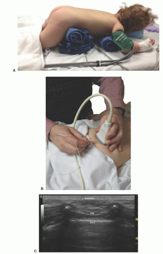 Figure 42.11. A: Prone position for caudal canal. B: Probe and needle position for caudal canal block. C: Ultrasound scan for caudal canal block. FCC, floor of caudal canal; SC, sacral cornu; SM, sacral membrane. |
 Tips
Tips
View both the long axis and short axis to provide two points of reference.
The epidural space is a potential space that is visualized best when the space is hydrodissected.
The lumbar spine offers better ultrasound visualization than the thoracic spine.3
Before insertion of the catheter, measure the disTance to the desired dermatome and insert the catheter initially the measured disTance. If the catheter does not coil, it can then be found near the desired dermatome and small adjustments more easily made.
References
1. Bösenberg AT, Bland BA, Schulte-Steinberg O, et al. Thoracic epidural anesthesia via caudal route in infants. Anesthesiology. 1988;69:265-269.
2. Marhofer P, Bosenberg A, Sitzwohl C, et al. Pilot study of neuraxial imaging by ultrasound in infants and children. Paediatr Anaesth. 2005;15:671-676.
3. Malas MA, Seker M, Salbacak A, et al. The relationship between the lumbosacral enlargement and the conus medullaris during the period of fetal development and adulthood. Surg Radiol Anat. 2000; 22:163-168.
4. Bubeck J, Boos K, Krause H, et al. SubcuTaneous tunneling of caudal catheters reduces the rate of bacterial colonization to that of lumbar epidural catheters. Anesth Analg. 2004;99:689-693, table of contents.
Part 4: Lumbar and Thoracic Continuous Epidural Analgesia via the Direct, Intervertebral Approach
Karen Boretsky
Paul E. Bigeleisen
Arvind Chandrakantan
Hadi S. Moten
Mihaela Visoiu
 Background and indications: For pediatric patients, the loss-of-resisTance (LOR) technique using saline solution is the classic technique for the placement of the epidural catheters directly at lumbar or thoracic levels. Ultrasonography with a linear high-frequency ultrasound probe can be used to identify neuraxial structures and to measure skinto-epidural space and dura depth, and it may permit visualization of the local anesthetic spread in epidural space and confirmation of catheter position.1, 2and 3
 Anatomy: Anatomy and sonoanatomy of spine were described earlier.
 Needle: 18G 5- to 10-cm Tuohy needle.
Related posts:
 Microanatomy of the Peripheral Nervous System and Stimulation Thresholds Inside and Outside the Epineurium
 Ultrasound-Guided Intraneural Injection—The Human Data
 Ultrasound-Guided Blocks at the Elbow and Forearm
 Ultrasound-Guided Distal Parasacral Block
 Fundamentals of Ultrasound-Guided Pediatric Regional Anesthesia
 Celiac Ganglion Block: Endoscopic and Transabdominal Approaches
Stay updated, free articles. Join our Telegram channel

Full access? Get Clinical Tree


