Transesophageal echocardiography (TEE) training and certification have become standardized with the use of recognized nomenclature and tomographic views. A consistent nomenclature has the advantage of not only facilitating communication between physicians but also promoting the performance of comprehensive examinations. Familiarity with standard views enables the echocardiographer to spot abnormalities more easily and compare sequential images. However, in some patients, it will not be possible to obtain a complete set of perfect two-dimensional views because of time constraints, or because the patient’s body habitus or anatomy impedes the ability to develop the appropriate imaging planes. With practice, a complete TEE examination generally can be performed in 10 minutes or less, with images recorded on videotape or, preferably, in a digital format. A written report should then be generated as part of the patient’s medical record (see Chapter 25). Recommendations presented in this chapter primarily pertain to the widely available TEE equipment, which permits multiplane two-dimensional imaging. As experience with the newly available real-time three-dimensional (3D) TEE grows, standardized recommendations are sure to follow.
Guidelines for a comprehensive TEE examination have been established jointly by the American Society of Echocardiography and the Society of Cardiovascular Anesthesiologists.1 The indications for performing a TEE examination continue to evolve on the basis of evidence attesting to its value and the weight of expert opinion and are listed in Table 5–1.2
I. Cardiac and Thoracic Aortic Procedures |
| • Cardiac and Thoracic Aortic Surgery |
| • For adult patients without contraindications, TEE should be used in all open heart (eg, valvular procedures) and thoracic aortic surgical procedures, and should be considered in CABG surgeries as well to |
| • Confirm and refine the preoperative diagnosis |
| • Detect new or unsuspected pathology |
| • Adjust the anesthetic and surgical plan accordingly |
| • Assess results of the surgical intervention |
| • In small children, the use of TEE should be considered on a case-by-case basis because of risks unique to these patients (eg, bronchial obstruction) |
| • Catheter-Based Intracardiac Procedures |
| • For patients undergoing transcatheter intracardiac procedures, TEE may be used |
II. Noncardiac Surgery |
|
III. Critical Care |
|
In fact, the decision to perform a TEE examination is influenced not only by the patient’s clinical condition but also by the setting in which the examination is to be done and the procedure or operation that is being done on the patient. Often, a combination of factors, each one a doubtful indication for TEE by itself, add up to a strong indication for a TEE examination. Further, a single TEE examination can answer, in a matter of minutes, a number of questions that would otherwise require several different tests. For example, a patient on a balloon pump who is unstable after coronary surgery can be examined with TEE specifically to evaluate the location of the intraaortic balloon pump, global left ventricular function, regional function that might reflect specific bypass graft patency, mitral valve competence, right ventricular function, and the presence of pericardial fluid collections. Important contraindications to performing a TEE examination are discussed in Chapter 25.
The TEE probe can usually be inserted into an anesthetized patient by displacing the mandible anteriorly and inserting the probe gently in the midline. Recent evidence, however, suggests that insertion of the probe under direct laryngoscopic visualization reduces the number of insertion attempts as well as the incidence of oropharyngeal mucosal injury and postoperative odynophagia (pain with swallowing).3 The transducer should never be forced through resistance upon entry into or passage through the esophagus. The tip of the transducer also should be maintained in the neutral position, and the control wheels (see following paragraph) must always be unlocked whenever advancing or withdrawing the probe. Flexion of the probe tip while in the esophagus should be performed with great caution and never with excessive force. Suctioning of gastric fluid and air with an “in-and-out” placement of an orogastric tube prior to probe insertion significantly improves the quality of transgastric images. Probe insertion in an awake patient presents additional challenges that are discussed in Chapter 25.
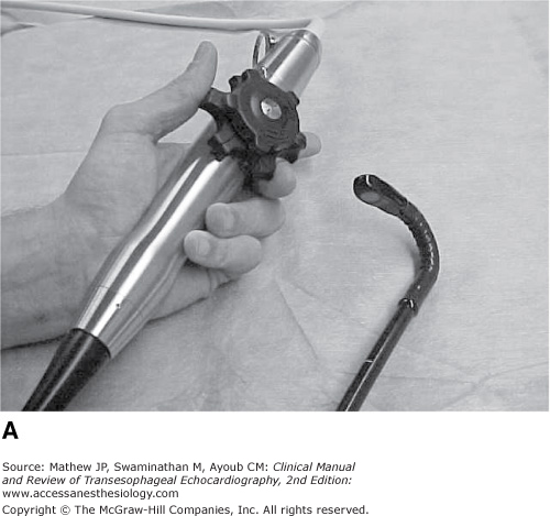
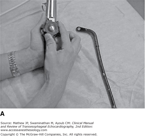
To view a particular image, the probe can be manipulated in four ways. First, it can be positioned in the esophagus to a certain depth; this technique is referred to as advancing and withdrawing the probe. Four esophageal “windows” are used to obtain TEE views corresponding to different positions within the esophagus (Figure 5–1). For example, many views will be obtained at a depth of about 35 cm from the teeth when the probe head (transducer) is generally posterior to the left atrium. This depth corresponds to a midesophageal position. Upper esophageal views would be obtained with the probe closer to a depth of 25 cm; transgastric views at about 40 cm and deep transgastric views might be obtained with the probe advanced to a depth of 50 cm. The second aspect of probe manipulation consists of flexion of the probe tip in four different directions by using the two control wheels located on the probe handle. The large wheel controls forward and backward movements of the probe tip. Forward motion of the probe tip is called anteflexion, in which the probe is flexed toward the sternum (Figure 5–2A). Backward motion of the tip is called retroflexion, when the probe is flexed back toward the spine (see Figure 5–2B). The smaller control wheel flexes the probe tip to the patient’s left and right and those motions are so described (Figure 5–3A and B). Lateral flexion to the left and right is much less useful than anteflexion and retroflexion.


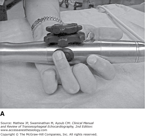
Third, the imaging plane provided by the transducer can be rotated axially through 180° by means of the lever or buttons located on the probe handle (Figure 5–4A and B). Multiplane probes permit this plane to be rotated forward from the 0° horizontal to a 90° plane, thus providing a vertical or longitudinal plane, and over to the horizontal plane again at 180° (a mirror image of that present at 0°). The imaging plane then can be rotated back from 180° toward 0° by electronically rotating the scanning plane backward (see Figure 5–4B). Fourth, the probe can be turned manually to the right and left sides of the patient, and this is referred to as turning to avoid confusion with the term rotation, which is applied to the electronic rotation of the scanning plane from 0° to 180°.

By convention, the transducer location (within the esophagus) appears at the top of the images, with the near field close to the transducer at the top and the far field below. The depth of the tissue being imaged is indicated by the centimeter markers at the sides of the image and on most machines by a numeric notation for the depth of field. At 0° the imaging plane is directed anteriorly from the esophagus through the heart, and the patient’s right side is presented on the left of the image display (when facing the display; Figure 5–5). Rotation to 90° progresses counterclockwise (the TEE probe tip is the clock face) from the 0° plane and presents the inferior portion of the heart on the left side of the display and the anterior portion on the right side. Rotation to 180° places the patient’s left side on the left side of the display, thus creating a mirror image of the 0° imaging plane.
Figure 5-5.

Position of the transesophageal imaging plane relative to the heart and the display screen. A: At 0°, the imaging plane is directed anteriorly from the esophagus through the heart, and the patient’s right side is presented on the left of the image display. B: Forward rotation to 90° progresses in a counterclockwise direction (probe as the clock face) from the 0° plane and presents the inferior portion of the heart on the left side of the display and the anterior portion on the right side. Note the change in the position of the white star on the imaging plane when the multiplane angle is rotated. C: Rotation to 180° places the patient’s left side on the left side of the display, thus creating a mirror image of the 0° imaging plane. Backward rotation results in a clockwise rotation of the imaging plane.
Two-dimensional imaging to examine cardiac anatomy
Color-flow Doppler imaging to visualize blood flow velocities
Spectral Doppler
a. Pulsed wave, to measure blood flow velocities at specific locations
b. Continuous wave, to measure high velocities that exceed the limits of pulsed Doppler and are commonly associated with abnormal flow jets
The complete examination should include the 20 views shown in Figure 5–6. The sequence in which these should be obtained is not rigidly fixed, but a specific order will permit the consistent performance of a comprehensive examination. One such sequence may start with midesophageal views, proceed to transgastric views, and end with the upper esophageal views. At times the echocardiographer may wish to go straight to an imaging plane that will answer a specific question such as the severity of regurgitation; however, a complete examination should always follow. Although 20 views are suggested for the complete examination, it may well be necessary to examine some nonstandard views. As every patient’s anatomy is different, one must not too rigidly follow suggested imaging depths or multiplane angles. A solid understanding of the anatomy provides the echocardiographer insight when a view is not ideal from a “standard” location. Three-dimensional imaging may be a useful guide in defining precise angulation necessary for “standard” views.
Figure 5-6.

The 20 two-dimensional tomographic views recommended for a complete transesophageal examination. Approximate multiplane angles are indicated by the icons adjacent to each view. (asc, ascending; AV, aortic valve; desc, descending; LAX, long axis; ME, midesophageal; RV, right ventricle; SAX, short axis; TG, transgastric; UE, upper esophageal.) (Reproduced with permission from Shanewise JS, Cheung AT, Aronson S, et al. ASE/SCA guidelines for performing a comprehensive intraoperative multiplane transesophageal echocardiography examination: recommendations of the American Society of Echocardiography Council for Intraoperative Echocardiography and the Society of Cardiovascular Anesthesiologists Task Force for Certification in Perioperative Transesophageal Echocardiography. Anesth Analg. 1999;89:870.)
The complete examination, as presented in the remainder of this chapter, will focus in turn on the following structures:
- Left ventricle (LV)
- Mitral valve
- Aortic valve, aortic root, and LV outflow tract (LVOT)
- Left atrium and pulmonary veins, right atrium, and atrial septum
- Right ventricle (RV), tricuspid valve, and pulmonary valve
- Thoracic aorta
- Views
- Midesophageal four chamber, two chamber, and long axis
- Transgastric two chamber and basal, mid-papillary, and apical short axis
- Midesophageal four chamber, two chamber, and long axis
- Assessment
- Contractility (fractional area change and ejection fraction)
- Segmental wall motion
- Chamber dimensions (dilation and hypertrophy)
- Masses (thrombus and tumor)
- Contractility (fractional area change and ejection fraction)
Assessment of the LV begins with the midesophageal four-chamber view to examine the size and overall contractility of the LV (Figure 5–7). This view is obtained at a depth of approximately 35 cm when the transducer is posterior to the left atrium. A 16-cm depth of field is usually appropriate to ensure that the entire apex is visualized. Forward rotation to 10° to 20° aligns the imaging plane with the true longitudinal plane of the LV, maximizes the tricuspid annular dimension, and excludes the aortic valve. A greater forward rotation may be required in patients with dilated ventricles or in patients undergoing redo procedures in whom adhesions can alter the normal lay of the heart within the pericardial sac. Gentle retroflexion is often also necessary to avoid foreshortening the ventricle and to visualize the left ventricular apex. The American Heart Association has recommended standardization of myocardial segmentation and nomenclature for tomographic imaging of the heart by any imaging modality (coronary angiography, nuclear cardiology, echocardiography, cardiovascular magnetic resonance, cardiac computed tomography, and positron emission computed tomography) and this recommendation will be followed in this chapter.4 Thus, in the midesophageal four-chamber view, the basal and mid-inferoseptal and -anterolateral myocardial segments, the apical septal and lateral segments, and the apical cap are visible.
Figure 5-7.


Anatomic (A) and ultrasound (B) illustration of the imaging plane as it cuts through the heart for the midesophageal four-chamber view. The basal, mid, and apical septal and lateral myocardial segments as well as the A3 segment of the anterior leaflet and the P1 scallop of the posterior leaflet are seen in this view. (RA, right atrium; RV, right ventricle; LA, left atrium; LV, left ventricle.)
Further forward rotation to 80° to 100° depicts the midesophageal two-chamber view (Figure 5–8) and rotation to 120° to 160° shows the long-axis view (Figure 5–9). While all three views are forms of long-axis views of the LV, only the imaging plane shown in Figure 5–9 is actually called the long-axis view. As with the four-chamber view, these imaging planes are used primarily to assess overall contractility and regional wall motion. In the two-chamber view, the basal, mid, and apical anterior and inferior myocardial segments are seen, and the long-axis view permits assessment of the basal and mid-anteroseptal and -inferolateral segments and the apical septal and lateral segments. The apical cap also is visualized in these two views.
Figure 5-8.


Anatomic (A) and ultrasound (B) illustration of the imaging plane as it cuts through the heart for the midesophageal two-chamber view. The basal, mid, and apical anterior and inferior myocardial segments as well as the P3 scallop of the posterior leaflet and the A1 and A2 segments of the anterior leaflet are seen in this view.(LA, left atrium; LV, left ventricle.)
Figure 5-9.


Anatomic (A) and ultrasound (B) illustration of the imaging plane as it cuts through the heart for the midesophageal long-axis view. The basal and mid anteroseptal and inferolateral myocardial segments as well as the A2 segment of the anterior leaflet and the P2 scallop of the posterior leaflet are seen in this view. (RV, right ventricle; LA, left atrium; LV, left ventricle; LVOT, left ventricular outflow tract; ASC AO, ascending aorta.)
Once the midesophageal views have been acquired, the TEE probe should be advanced to the transgastric position. Anteflexion of the tip of the probe is necessary to produce the basal (Figure 5–10), midpapillary (Figure 5–11), and apical (Figure 5–12) short-axis views. Care should be taken to ensure that the entire LV is seen on the image, which usually requires a depth of field of 12 cm and some probe turning. The LV also should appear circular, particularly with the basal short-axis view, where excessive anteflexion commonly results in imaging of the membranous portion of the interventricular septum and/or portions of the LVOT, making it difficult to accurately categorize myocardial segments and thus assess regional wall motion abnormalities. Tangential imaging planes may be corrected by reducing the anteflexion, advancing the probe, or lateral flexion of the tip of the probe.


Figure 5-11.


Anatomic (A) and ultrasound (B) illustration of the imaging plane as it cuts through the heart for the transgastric mid short-axis view.
Related posts:


Stay updated, free articles. Join our Telegram channel

Full access? Get Clinical Tree


