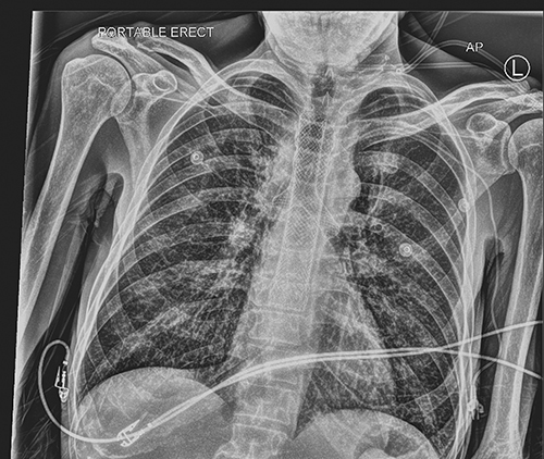
Karen McRae A large variety of tracheal stents are currently available; each has advantages and drawbacks. Team planning is essential before these challenging procedures and should be clearly outlined in the checklist before starting. Recent airway imaging is essential. Some straightforward lesions may be stented using flexible bronchoscopy; more complex cases usually require rigid bronchoscopy. A supraglottic airway device should be immediately available, as well as a flexible bronchoscope and rigid bronchoscopes in a range of diameters. Life-threatening central airway obstruction can occur; a rescue strategy should be devised in advance. There may need to be a transition between different airway instruments to maintain tracheal patency with a corresponding change in ventilation strategy. In specialized centers, extracorporeal membrane oxygenation may be used to support ventilation in complex cases. stent; tracheal stenosis; tracheal fistula; bronchoscopy; ECMO An airway stent is a prosthesis inserted to maintain intraluminal integrity of a compromised conducting airway, which can consist of either relief from airway obstruction or restoration of patency of the airway, such as in the case of fistulas or airway dehiscence. Placement of central airway stents is the domain of both the thoracic surgeon and interventional pulmonologists. Both benefit from the provision of expert anesthesia care and should be experienced colleagues in management of the shared airway. Patients with a variety of challenging pathologies present for airway stenting (Table 51.1). Table 51.1 Traumatic: Postintubation, blunt or penetrating trauma Inflammatory: Amyloidosis, sarcoidosis, relapsing polychondritis, Wegener Infectious: Tuberculosis, papillomatosis, postviral Neoplastic: Hemangioma, hamartoma, chondroma, neurofibroma, broncholith Anastomotic (stenosis or dehiscence): Postpulmonary transplant, sleeve resection Vascular: Vascular rings, thoracic aneurysm Tracheomalacia Malignant Endobronchial tumor: Bronchogenic, adenoid cystic, carcinoid, mucoepidermoid Extrinsic compression by tumor or lymphadenopathy Primary: esophagus, thymic, thyroid, germ cell, lymphoma, sarcoma Metastatic: Bronchogenic, renal cell, colon, melanoma, breast Tracheoesophageal fistula The ideal airway stent would be easy to place with low morbidity, while reliably reestablishing the integrity of the airway. Optimally, it would have minimal tendency to migrate, while being able to be easily removed if required. The ideal stent should have sufficient strength to support the airway, but flexible enough to allow clearance of secretions, and biologically inert to minimize the formation of granulation tissue. Long-term luminal patency should be maintained without causing ischemia, or erosion into adjacent structures would be possible. Unfortunately, to date, no currently available stent possessed all these characteristics (Table 51.2). Each patient’s underlying condition and anatomy must be considered when choosing a device.1,2 Table 51.2 Removable Resist external compression Least formation of granulation tissue Higher rates of migration Thick walled so smaller inner lumen Mucus plugging Unable to conform to irregular shaped airway Flammable (risk during laser therapy) Less migration Thinner wall, increased inner diameter Lesser impact on ciliary function Wall pressure may cause necrosis and fistula formation Tumor may regrow along length of stent May collapse with external compression May be placed with flexible bronchoscopy Less migration Thinner wall, increased inner diameter Lesser impact on ciliary function More easily removed than bare metal SEMS Formation of granulation tissue at ends may block stent Contain flammable material (risk during laser therapy) May collapse with external compression Recently, the types and sizes of stents currently available were comprehensively reviewed.3 There are three main varieties of stents: silicone, and self-expanding metal stents (SEMS) available in covered (typically with Silastic or polyurethane) and uncovered designs (Fig. 51.1). SEMS are generally more easily inserted; many centers routinely place them via flexible bronchoscopy. They can, however, be very difficult to remove. For malignant airway obstruction, covered models prevent tumor ingrowth. Uncovered metal stents are optimal for conditions in which the formation of granulation tissue is desirable, such as airway dehiscence. Epithelialization of the stent occurs within weeks of placement, which preserves mucociliary activity and reduces the risk of mucous plugging. An advantage of metal stents is their thin walled structure; and their internal to external diameter is larger than silicone stents. Silicone stents require placement using rigid bronchoscopy, but are far more easily removed. The rate of stent migration is higher with silicone than metal. Other characteristics of classic stent designs are outlined in Table 51.2. A 49-year-old man with esophageal carcinoma was treated with chemotherapy and radiation. He subsequently developed a tracheoesophageal fistula. An esophageal stent was placed in a community hospital; however, he developed erosion into the trachea. He was taken to the operating room for evaluation of the trachea and probable stenting. Anesthesia was induced with 50 mg lidocaine, 20 mcg of remifentanil, 20 mg of ketamine, and 150 mg of propofol, intravenously followed by a propofol infusion of 80 mcg/kg/min. A No. 4 laryngeal mask airway (LMA Unique, Teleflex Medical) was placed, and the patient resumed spontaneous ventilation, as no muscle relaxant was administered. Upon detailed inspection, there was an obvious area in the mid to distal trachea where the stent had eroded into the membranous airway. There was also an area just proximal to the carina where a second fistula was visualized. A partially covered self-expanding Ultraflex metallic stent was placed, which was 20 mm in diameter, 45 mm in covered length, and 60 mm in total length. A guidewire was inserted into the trachea under direct vision via the bronchoscope working channel, over which the stent was threaded and deployed with the aid of fluoroscopy to confirm positioning (Fig. 51.2). The LMA was briefly removed during stent deployment, and high-flow oxygen was administered via nasal cannula until the wire was removed and the LMA replaced. After the propofol infusion was discontinued, emergence was uneventful. The procedure lasted an hour with spontaneous ventilation throughout while the fraction of inspired oxygen (FiO2) was maintained at 0.8 throughout, and there were no episodes of desaturation. The combined esophageal and tracheal stenting was effective for some time (Fig. 51.3); however, on radiologic follow-up 3 months after tracheal stent placement, there was a suspicion of further erosion of the esophageal stent into the distal membranous portion of the trachea, extending into the left main stem bronchus (Fig. 51.4). This was confirmed during awake flexible bronchoscopy after upper airway topicalization. The right bronchus was normal, and on the left side, there was erosion of the esophageal stent into the membranous portion of the left main bronchus. The distal left bronchus, left upper lobe, and left lower lobe were normal. It was determined that placement of a Y-stent would be required after removal of the in situ tracheal stent. Measurement of the tracheal and bronchial lengths were made to allow acquisition of a Y stent of the appropriate dimensions. A few days later, general anesthesia was induced with Midazolam 1 mg, Fentanyl 50 mcg, propofol 100 mg, followed by rocuronium 25 mg. A No. 4 LMA Supreme was inserted, followed by controlled positive pressure ventilation 10 cm H2O over 4 cm H2O of positive end-expiratory pressure (PEEP). Infusions of propofol 75 mcg/kg/min and remifentanil 0.1 mcg/kg/min were started. The airway was reexamined distal to the existing tracheal stent; the esophageal stent could be visualized in the posterior left mainstem bronchus. The LMA was removed and a size 8.5 rigid bronchoscope was inserted into the trachea. Intermitted ventilation with jets of 100% oxygen via a handheld Sanders injector device allowed ventilation via the open rigid bronchoscope with periods of apnea without desaturation. Using rigid bronchoscope forceps, the tracheal stent was grasped and removed together with the rigid bronchoscope. The LMA was reinserted. Flexible bronchoscopy revealed the membranous portion of the distal trachea extending into the left main bronchus to be absent; the esophageal stent was clearly visible. A fully covered self-expanding metallic Y-stent from Micro-Tech with the tracheal diameter of 20 mm, tracheal length of 40 mm, left main bronchus length of 30 mm, and right main bronchus length of 15 mm was placed. To accomplish this, the LMA was removed, and the trachea was again intubated with the rigid bronchoscope. Visualizing with the flexible scope through the rigid bronchoscope, a long guidewire was inserted into the left, and a shorter guidewire was then inserted into the right main bronchus. The flexible scope was removed, and the patient was preoxygenated as much as possible with jet ventilation; the rigid bronchoscope was removed, leaving the wires in place. The left and right tips of the stent were threaded over the proximal ends of the guidewires. The stent delivery system was inserted into the trachea over the guidewires. Before deployment, the flexible bronchoscope was inserted beside the apparatus to be able to visualize the tips of the stent. The stent was deployed distal ends first after ensuring that the Y portion was seated on the carina. Thereafter, the tracheal part of the stent was fully deployed. Full stent deployment took several minutes and was performed during apnea; there was a brief period of desaturation to 85%, which resolved immediately with face mask ventilation once the stent was deployed. The LMA was reinserted and flexible bronchoscopy was performed. The Y-stent had completely covered the defect in the membranous portion of the trachea, as well as extending into the left main bronchus (Fig. 51.5). Neuromuscular relaxant was reversed, and with discontinuation of propofol and remifentanil infusions, the patient emerged uneventfully from anesthesia. This case illustrates how many patients require multiple interventions, which can include not only initial stent placement, but later stent removal, revision, and replacement. Straightforward stenting may be placed using flexible bronchoscopy, whereas more complex procedures usually require rigid bronchoscopy, facilitated by fiberoptic bronchoscopy. A 38-year-old patient with advanced colorectal cancer had undergone primary resection, as well as hepatic and bilateral lung metastectomies. She had developed an extensive mediastinal lymphadenopathy, presenting with significant shortness of breath and wheeze. Imaging showed near-complete occlusion of both main bronchi at the level of the carina (Fig. 51.6). She was brought to the operating room on an urgent basis because the airway narrowing appeared to be due to airway invasion, as well as from external compression. Rigid bronchoscopy for tumor debridement and stenting was planned. A lengthy and potentially difficult procedure was anticipated, and the decision was made for planned use of venovenous extracorporeal membrane oxygenation (ECMO) support of gas exchange. After a comprehensive informed consent discussion, the patient was brought to the operative room, a large bore peripheral intravenous and radial arterial catheter were placed. After preoxygenation, anesthesia was induced with lidocaine 50 mg, fentanyl 100 mcg, propofol 50 mg, ketamine 60 mg, and followed by rocuronium 60 mg. We were able to confirm immediately that she could be ventilated with positive pressure, and she was intubated with a 7.5 standard endotracheal tube (ETT). Initially, low-dose Sevoflurane was used during flexible bronchoscopy and ECMO cannulation, with conversion to total intravenous anesthesia (TIVA) with propofol infusion of 100 to 120 mcg/kg/min and remifentanil 0.05 to 0.1 mcg/kg/min titrated to effect while on ECMO. Flexible bronchoscopy showed a very extensive tumor in the level of the carina, extending to both right- and left-main bronchi (see Fig. 51.6). A dual lumen catheter was inserted into the right jugular vein under sterile conditions with ultrasound guidance to locate the jugular vein and with verification of catheter position with fluoroscopy. A 28 Fr Crescent cannula was used and ECMO flows of 3.5 to 4 L per minute L/min were targeted (Fig. 51.7). Heparin dosing was targeted an activated clotting time ( ACT) of 160 to 180; only one 4000-unit bolus was required. After initiation of apnea, blood gases were drawn and good oxygenation and ventilation were confirmed. The ETT was removed and the patient remained apneic during the stenting procedure, which lasted approximately 130 minutes (Figs. 51.8 and 51.9). An 8.5-mm rigid bronchoscope was inserted, and extensive debridement of the tumor in the carina and both right and left bronchi was performed. Much of the endobronchial tumor was removed but there was still a significant degree of extrinsic compression, especially in the bronchus intermedius. Balloon dilatation was attempted to widen the right airways, without clear success. The decision to place a carinal Y stent was made: a Micro-tech self-expanding, fully-covered wire Y-stent was chosen. A 4 cm extension into the trachea, 2 cm into the left main bronchus, and 1.0 cm into the right main bronchus was positioned and deployed in a similar manner as described in Case 1 (Fig. 51.10). Because of the ECMO support, no interruptions for ventilation were required. The patient was hemodynamically stable throughout the procedure. The stent was placed in an optimal position without occluding the orifice of the right upper lobe bronchus. The surgeons achieved satisfactory hemostasis, especially on the right side, with a clear opening of the airway and minimal bleeding.
Tracheal Stents
Abstract
Keywords
Introduction
Benign
Stent Type
Advantages
Disadvantages
Silicone
Inexpensive
Require rigid bronchoscopy
Uncovered self-expanding metal stent (SEMS)
May be placed with flexible bronchoscopy
Difficult to remove
Covered SEMS
No tumor growth along length of stent
Wall pressure may cause necrosis and fistula formation

Case Presentations and Management
Case 1


Case 2


Related posts:
![]()
Stay updated, free articles. Join our Telegram channel

Full access? Get Clinical Tree


Tracheal Stents


